Save the circuit for the next lab when you will build a ventricular cell model and connect them.
Introduction.
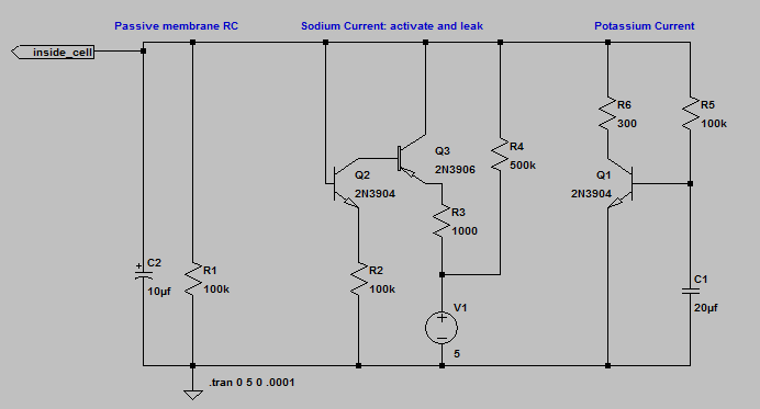
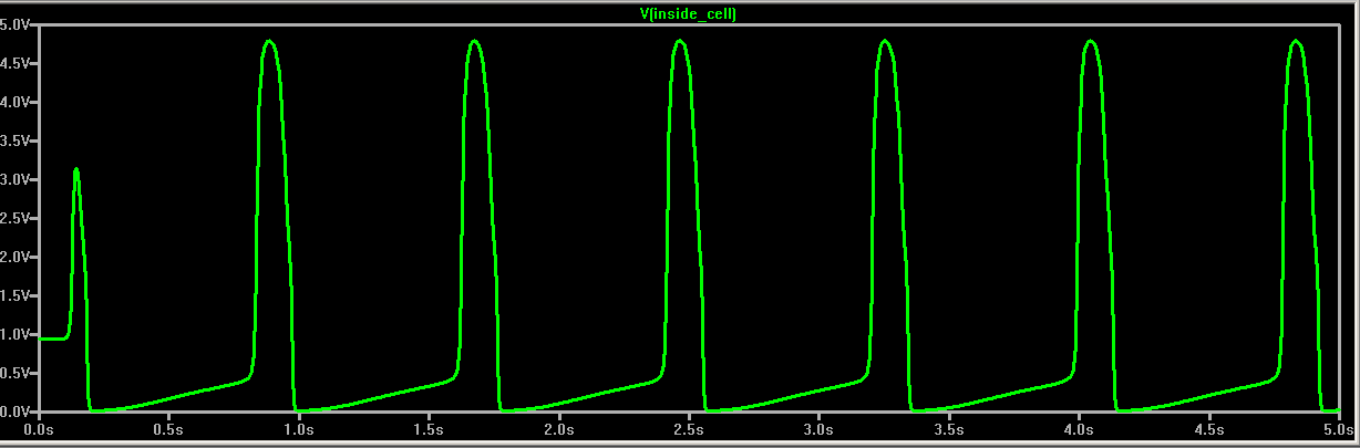
The goal over the next four labs is to build an electrical model of a beating heart. In this lab you will investigate RC circuits and transistor circuits used to simulate the biological channel structures which let ions (electrical current) in and out of heart, muscle, and nerve cells. Electrically active cells in the body have several kinds of ion-passing channels which are sensitive to cell membrane voltage. These can pass sodium ions (fast and depolarizing), potassium ions (slow and repolarizing), or mixtures of ions (slow and partially repolarizing). RC circuits will be used to set the time of activation of all the channels and to simulate the speed of response of the cell membrane.
Background:
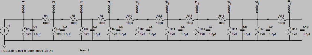
Since channels respond to voltage by changing their resistance, we will be measuring the curves of current versus voltage for several circuits. If the circuit were just a resistance, then plotting current versus voltage would be linear with a slope of 1/R (since I=V/R). Transistors allow us to design circuits with very nonlinear I-V curves, just like the biological ion channels we want to model. If there were no voltage-dependent amplifier channels, then voltage pulses would quickly die out and neither nerves nor muscle could work, so we will start by looking at passive RC circuits.
Transistor characteristics:
Collector current, Ic, is an exponential function of the voltage between the base and emitter, Vbe. Vt is a constant which depends on the absolute temperature and at 300K (room temp) Vt=0.026 volts. Ies is a constant which depends on transistor construction but is commonly around 10-12 amps. We can write the collector current as:
Ic = Ies (e(Vbe/Vt) - 1)
which basically says that for every increase of Vbe by 0.026 volts (26 millivolts), the current increases 2.71 times. Note that the real transistor will burn or explode if the current becomes greater than about 0.1 amp.
Axon characteristics:
The current through the sodium channel increases exponentially 2.71 times (e) for every 7 millivolts of voltage increase, or about 4 times faster than a transistor.
Ichannel = Ileak (e(4*Vchannel/Vt) - 1)
A transistor is a good model in that the current is exponenential, but a weaker model for channel sensitivity.
Assignment:
Note that in this and every lab assignment the verb build means to construct a circuit on the protoype board with actual parts.
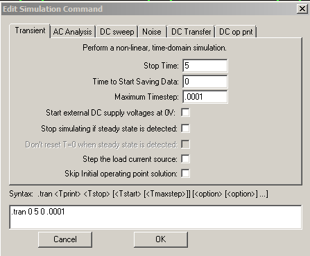
The verb simulate means use LTspice to mathematically simulate the circuit.
This exercise is part of the next several lab assignments. There will no written lab report from this exercise, but you will need the data from this lab when you do the writeup at the end of lab 4.