Cornell University ECE4760
Analog techniques
Motor Controller
Building a compact motor controller.
Solderless proto-boards do no work well for high current motor controllers. They melt.
A compact design for the ece4760 motors lab can be fabricated on a small piece of solder board.
The board is more reliable and is easy to reuse for other projects.
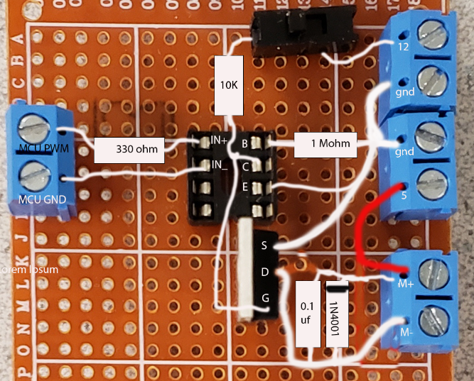
The image below is kind of a hacked together mash-up of a schematic and photograph, but hopefully shows the connections.
NOTE that all the connections to the blue terminals are to be soldered to the bottom, not pushed thru the tiny holes on the top.
In fact, most of the white lines representing connections should be on the bottom of the board.
The rectangular black object at the top is a SPST kill switch. The DIP socket is wired for a 4N35 optoisolator.
Below the DIP socket is an N-channel power MOS-FET.
The actual schematic.
The motor is shown as a simple inductor. The kill-switch shown above is in the run position.
If you insert the diode in the wrong polarity it shorts the power supply and destroys the diode.
Note that it is the low bandwidth of the 4N35 that constrains the PWM frequency to about 1kHz.
The 5 volt supply will go to a wall-wart type supply. The bench supply will supply the 12 volts.

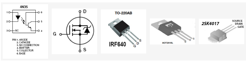
The pinouts for the 4N35 optoisolator and various power MOSFET's are shown below.
If you find that the FET is too hot to touch, you should clip or screw a heatsink to the tab on the FET.
The image below shows a heatsink clipped on. The kill-switch is on the right.

A top-view of the board.

Copyright Cornell University
March 14, 2025
