

Introduction
For our ECE 4760 Final Project, we use an infrared LED and phototransistor armband to detect muscle inflections in arm and wrist movement which are used to manipulate the volume and speed of pre recorded songs. By pumping your fist, you will change the speed at which the song is playing. Isolated wrist movements correspond to volume changes. By moving your hand towards your body in an upward motion, you increase the volume. By moving your hand towards the ground in a downwards motion, you decrease the volume. Other similar motions that provide similar phototransistor outputs can be used to control volume as well. We use a signal peak and fall detection system to control sound. A push button is used to rotate between three Michael Jackson classic songs. We use the UART to display initial directions and other messages to the user to aid in the users activity. We both enjoy various types of music and thought manipulating sound based on muscle movements would be interesting and could lead to other practical applications.
High Level Design
Motivation and Rationale
Both team member are large fans of music, so music became the main focus and drive for the final project. We had various ideas of how to produce or manipulate sound. We decided to use the detected light reflected from IR LEDs against muscles in the arm to manipulate various aspects of songs. Later, we chose to program Michael Jackson classic songs with the hopes to appeal to a large audience of very taste of music and various age groups. The songs were catchy, fit the beat timing requirements, and recognizable within the first few notes.
The system is highly usable by all age groups, requiring very minimal training. The system has preset thresholds to determine the level and location of muscular activity. Furthermore, we expect that this method of playing electronic music is highly conducive to users with special needs. The LEDS and phototransistors may be placed on any body part which the user is able to control. As a result, a user who cannot use his or her hands to play music, as is often required for musical instruments, may use this device to manipulate a song or other useful things by moving a muscle group.
Our original proposal was to build an infrared LED and phototransistor armband that will detect muscle inflections of finger movement. With the Phototransistor output, we hoped to imitate a small piano with various notes corresponding to the movement of specific fingers. Using the LCD, we wanted to display initial directions and other messages to the user to aid in the users activity. Also, the musical key would be user specified using the keypad. Throughout testing we determined that we were not about to specify individual finger movements, thus we focus on larger muscle groups. Our project has morphed throughout the design process based on our results from testing, feasibility, and our interests.
Logical Structure
Our main hardware consist of an armband with 4 LEDs and 2 phototransistors outputted to a filtering system and then feed into the ADC. There are two main parts to our software; the time sensitive interrupt, and the less time-sensitive functions. In the time-sensitive interrupt collect ADC samples from sensor, detect peaks and falls from the ADC samples, and output the sound. In the less time-sensitive Main functions, we update song and frequency changes and perform data processing in order to manipulate sound.
Mathematical Background
In this project, software peak detection is applied to amplified phototransistor signals by checking for a specific amplitude and direction of change relative to a baseline value. Both of these elements are essential for correct peak detection. For example, when detecting a signal rise above threshold, an above-threshold value and a simple threshold crossing are not enough to show that the condition has occurred because the signal must also be increasing. All of these necessary conditions hold specifically when one sample of a signal is below the set threshold and the next sample is above it. Correct implementation of this peak detection is included based upon code suggested in an earlier ECE 4760 lab and is described by the code below.

The method of sound synthesis used in this project was based upon a common model of FM sound synthesis to create tones similar to those produced by musical instruments. Essentially, the phase of a sine wave is varied according to a second sine frequency of some scaled amplitude and the resulting phase-modulated sine is amplitude-scaled so that the tone appears to grow and decay, as shown in the following equations:

This method is highly useful to digitally synthesize sounds in an easily codable and understandable way while producing complex and realistic sounds. Low FM frequencies (denoted by (omega)2) produce sine wave segments with slightly varying frequency and little other distortion, but as FM frequency increases, the waveforms become increasingly distorted and appear inherently different from a sine wave. This project ultimately did not include the sine-varying phase term that creates FM synthesis in order to preserve simplicity, resulting in sound synthesis governed by the equation below.

This equation essentially models an instrument that produces a waveform with little distortion, such as a bell or chime.
Hardware/Software Tradeoffs
The project’s most important tradeoffs between software and hardware design are in conversion between digital and analog signals. These concerns include filtering of the phototransistor signals (A/D conversion) and conversion of digital waveform calculations to smooth sine-wave analog output (D/A conversion). Both of these functions were implemented using hardware more than software; we generally avoided making the software unnecessarily complex in order to conserve memory and execution time of the MCU since our code stores several long floating-point vectors and performs two complex functions. Filtering of the sensor signal inputs was performed completely in hardware, though there are many digital signal processing algorithms which could serve the same function. Conversion from digital to analog sine output was also performed completely in hardware using the DAC chip, but software could have been used to convert this signal to a single PWM voltage output and, with fast enough timing, even low-pass filter that output to be a fairly smooth sine wave. The one ambivalent function performed in software rather than hardware is peak detection, which could have been implemented using a simple op amp circuit.
Hardware Design and Implementation
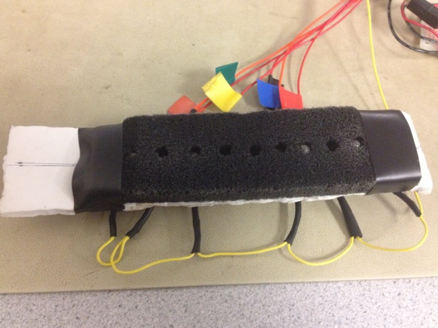
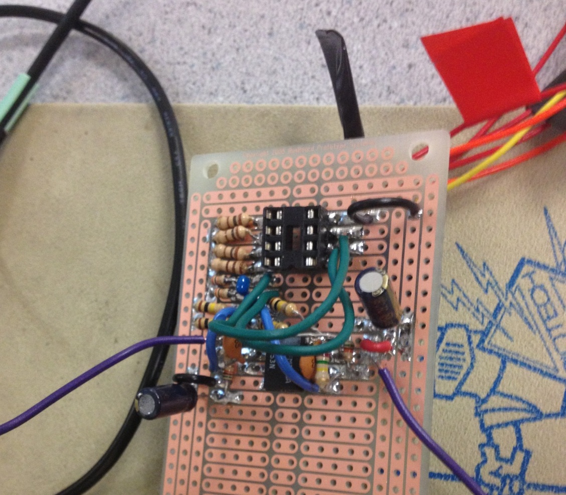
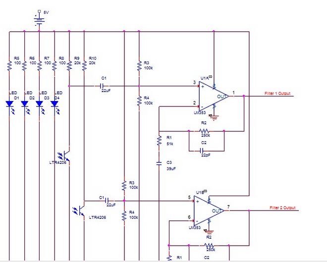
IR LED and Phototransistor ArmbandWe built an armband with integrated infrared LEDs and phototransistors. The final armband has two phototransistors with an LED to the right and left of the phototransistor. The armband will be vertically positioned on the arm so that it can detect the muscle inflections on commonly used muscles for gripping and lifting. The infrared LED will illuminate the muscle and the light reflected from the muscle will be detected using the phototransistors. We are able to isolate the various phototransistor outputs to detect which muscle is being moved and causing the greatest output. The design of the armband is based on a 1’ 7/16 inch width, 6’ ¾ inch length , and ¼ inch thick piece of cardboard. The LEDs and phototransistors are placed in sequence along the middle of the cardboard, 3/4’ from the top of the board. The LEDs and phototransistors were placed through the cardboard. All LED hot leads were connected to individual red wires. All phototransistor hot leads were connected to individual orange wires. LED and phototransistor ground leads are all connected with one yellow ground wire. Heat shrinks were placed on all connections to prevent shortages. After building our first main sensor armband, we acquired black foam. We a large block of black foam with a butter knife to the shape of the cardboard a couple of centimeters in thickness. We cut small holes through the black foam just large enough for the LED and phototransistor heads and laid the foam along the cardboard. The black foam is used instead of tape to block out light.

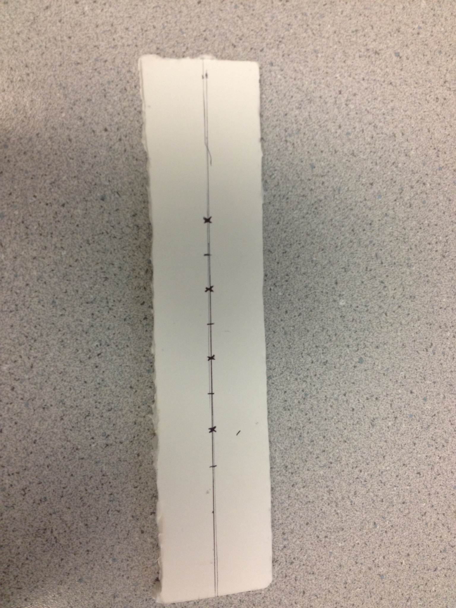
The ends of the sensor are numbered 1 and 2 in order to determine thecorrect direction to place the sensor along the user’s arm. The sensor closest to end 1 is routed to Port A1 (ADC channel 1) and senses muscle movements close to the wrist, while the sensor closer to end 2 is routed to Port A2 (ADC channel 2) and is placed closer to the center of the forearm, sensing large-scale arm movements. The first channel sensor can sense fine movements, especially in the wrist and hand, while movements in the second channel tend to produce much smaller signals and only capture large whole-scale arm movements. These differences are partly compensated by having the sensor band use a phototransistor experimentally found to be more sensitive as the mid-forearm sensor. These signal differences are also accounted for in detection software by choosing detection thresholds according to the different levels expected for each sensor channel.
Note: For LED and Phototransistor Circuit Schematic, See Appendix| Arm Band Parts |
| R5 = R6= R7 = R8 = 100 |
| R9= R10 = 20k |
| LTE4208 (quantity = 4, LEDs) |
| LTR4206 (quantity = 2, Phototransistors) |
Audio Amp Driver
A audio buffer circuit is used to drive two Logitech S-120 speakers designed for computers. The circuit uses the Sallen-Key topology in a common configuration which acts as a unity-gain amplifier in order to provide powered audio output to the speakers based on the DAC waveform, which is driven by the low-power microcontroller and is not conducive to the high-power consumption needed for speakers. The MCU output waveform has a voltage range (0V-5V) high enough that no additional voltage level amplification is needed.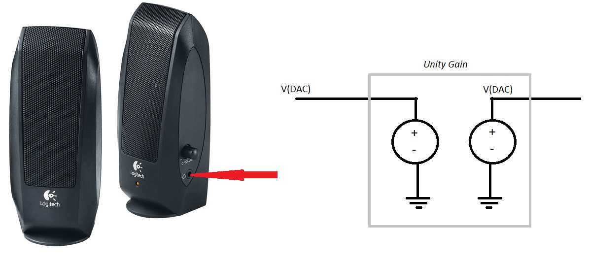
For a full schematic diagram of the audio driver amplifier, please refer to Appendix.
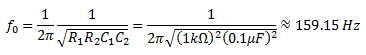
Additionally, this amplifier configuration serves as a slight low-pass filter. The time constant and cut-off frequency cut-off frequency are calculated using published equations (source) and are found to be:
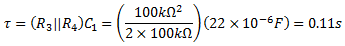
Filters System A dual filter and amplifier unit was designed to process signals from each phototransistor sensor in hardware before routing the signal to software. One filter subsystem acts upon the output of each, using a LF353N op amp to translate the sensor signal to an output of greatly increased amplitude and maximal swing. Firstly, it removes DC offset by placing a large capacitor C1 on the input branch and fixing the end ofthis capacitor input to a voltage divider of equal resistance between 0V ground and MCU Vcc=5V so that the input signal is centered in the output voltage range of the amplifier. The signal at the middle of the divider is then routed to the non-inverting input of an op amp. Values for the voltage divider resistors were made as large as possible, but their size was limited by their contribution to the input time constant, which must be small enough to allow passage of movement-generated signals, which may be as fast as 0.1 s. Using final component values, this input circuit effectively creates a high-pass filter with a time constant of:
This value is large enough to admit all relevant signals on the time scale of human arm movement and small enough to remove meaningless DC offset and slow amplitude variations. In the feedback and filtering networks discussed below, a capacitor is connected between an inverting input resistor and ground, giving the circuit unity gain for DC components onthe non-inverting input. The output then has a filtered and greatly amplified reflection of the small AC component at the input while keeping the same desirable DC value seen at the input. The exact gain applied to the is not known and is notgiven in the LF353N datasheet, but it generally produces AC sensor signals around 0.5V to 2V in amplitude and is deemed acceptable for these inputs.
The subsystem also serves to filter relative high-frequency noise in the sensor signal. The inverting input and ground are joined via a series RC connection, which may be viewed as a high-pass filter, and a parallel low-pass filter is placed in a feedback loop between the output and non-inverting input. Originally, we intended to filter 60 Hz noise produced from ambient light, but after plenty of experimentation with the filtered signal, it was determined that having a much higher low-pass filter cutoff frequency allowed for larger and more detectable signal voltage changes and did not appear to increase 60 Hz noise seen in the signal. Assuming that each of these branches has a simple RC time constant, their time constants are given by:

The following chart contains component values which are used in the filters and and govern the circuit equations given above. For a detailed schematic diagram of the photodiode filter system, refer to Appendix.
| Original Filter System Parts (x2) | Final Filter System Parts(x1) |
| R1 = 51kΩ | R1 = 51kΩ |
| R2 = 450kΩ (430kΩ in series with 20kΩ) | R2 = 250kΩ |
| R3 = 100kΩ | R3 = 100kΩ |
| R4 = 100kΩ | R4 = 100kΩ |
| C1 = 20uF | C1 = 22uF |
| C2 = .1uF | C2 = 22pF |
| C3 = 43uF | C3 = 39uF |


The amplifier boards consisted of a pre-amplifier, re-biasing, and ac-gain stage. The pre-amplifier stage was needed to help buffer the sensor input as well as to reduce the amount of AC-gain needed in the final state. Having such a large gain in one stage resulted in component values that were either too expensive or infeasible to make fit in such a close space. An emitter degeneration resistor was added to the common-emitter state to reduce the amount of variation between outputs of sensors due to individual device variations of the transistors.
The capacitor, C1, before the common-emitter stage removes the DC bias from the signal in order to maximize gain without railing. C2 removes the DC bias from the output of the common-emitter stage and the voltage divider formed by R6 and R6 re-bias the signal at approximately 2.5V. Together, this keeps the signal as close to the middle of the dynamic range (0-5V) as possible.
Finally, the AC-gain stage provides the amplification necessary to take up the majority of the ADC’s dynamic range. It functions as a standard non-inverting amplifier with the exception of a capacitor to ground in the feedback loop. This blocks the DC portion of the signal from being amplified since impedance for the capacitor is \(\frac{1}{j\omega C}\).
DAC
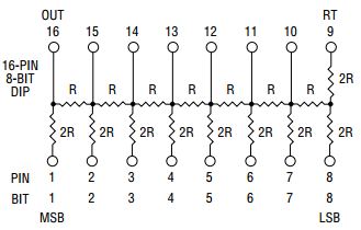
Conversion from the 8-bit digital sound output from the MCU to an analog, sinusoidally varying speaker signal was performed in hardware using a Bourns R/2R ladder DAC chip in 8-bit DIP conformation. The chip entirely consists of a passive resistor network where resistances between any bit pin and the output are scaled according to the significance of that bit. The most significant bit is placed at pin 1, closest to the output, and assigned the lowest output resistance (R2); the resistance seen from the output pin into the rest of the circuit reduces to 2R, so the voltage at pin 1 is scaled by ½ at the output. Only ¼ of the voltage that appears at , and so on for bits of lower significance. The least significant bit is farthest away from the output and is divided by the largest exponent of 2. The voltage contributions of each bit pin will add, and assuming that all bits have the same low and high voltage levels (for Mega1284, 0V and 5V, respectively), the output will then scale linearly between logic high and logic low voltages as the 8-bit input increases from 0 to its maximum value 28 -1. Below is the on-chip resistor network which creates these results.
Speaker Wiring
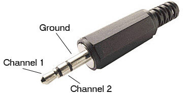
The speakers are used to output the audio notes controlled by phototransistor outputs. Below is an image of the the audio connection leading to speakers. Alligator clip cables were used to connect the ground of the audio cable to our circuit common ground and the left speaker input to the audio driver amplifier.
Push Button:
We are using the push button to switch between songs. We have programmed the frequencies for a total of three songs by Michael Jackson. When the push button is toggled, the input pin to which it is attached, is read directly by saving the input register PINC in a variable “push” and comparing it with a corresponding bit mask, as described in “Software, Main.”
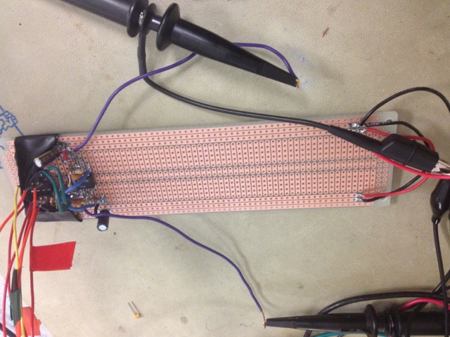
Hardware TestingThroughout the testing process, we were able to make changes to multiple aspects of the hardware design. Originally, each LED has a phototransistor to its right. There were 4 LEDs and 4 phototransistor. We started testing by placing two phototransistors and two LEDS in a fabric armband. We were getting sufficient output signals so we moved a single phototransistor and LED to a small piece of cardboard. We then placed tape around the edges to direct light and light detection. We also added amplifiers and a high pass filter to the phototransistor outputs. We were happy with the filtered output signal. So, we cut a longer piece of cardboard and placed 4 LEDS and 4 phototransistors in a row on the cardboard and wrapped them with tape. When testing all four LEDs and phototransistors across two oscilloscopes, we found that it was hard for all of the signals to work simultaneously. We would pick up movement in one of the signals but not the others. We were using banana plugs to connect all of the LEDs and phototransistors leads so we thought that the best next step would be to solder all of the leads to have a secure connections. We then added the black foam to the armband to help block out exterior light.
After the armband was built, all LEDs were found to be on and all phototransistors produced a light detection signal. Building and testing these four filtered signals took a lengthy amount of time due to building time, time debugging, and time analyzing the outputs. The sensor drew unusually high current levels (around 0.17A), which we attributed to one of the middle LEDs begin blown out, which was found to have a very low voltage. We then disconnected the LED, and the current dropped to .05A. Two oscilloscopes were used to measure all phototransistor signals simultaneously. All phototransistors could detect movement at different times but we were only able to get one or two channels to respond during any one trial. Therefore, it was decided that the sensor could not reasonably produce a signal specific enough to create sound based on individual finger movements and our project should instead focus on modulating pre-calculated sound using large-scale arm and hand movements. We then began to focus testing on the two phototransistors that were providing detectable outputs and hooked up one phototransistor output to ADC.
Our first filter design was implemented with the parts available in lab. Once we fine tuned the desired cut off frequencies, we were able to place an order to DigiKey and receive components. Below shows the original and final filter system parts.
| Original Filter System Parts (x2) | Final Filter System Parts(x1) |
| R1 = 51kΩ | R1 = 51kΩ |
| R2 = 450kΩ (430kΩ in series with 20kΩ) | R2 = 250kΩ |
| R3 = 100kΩ | R3 = 100kΩ |
| R4 = 100kΩ | R4 = 100kΩ |
| C1 = 20uF | C1 = 22uF |
| C2 = .1uF | C2 = 22pF |
| C3 = 43uF | C3 = 39uF |
During testing of the phototransistor signals at the ends of the bands, we concluded that there is a strong signal for fist clenches at the phototransistor closest to wrist and no signal at the phototransistor farthest up arm. We also concluded that there is a resulting signal change from strong and slow fist pumps in both phototransistors. For slow pumps, there is a gentle change where fast pumps induces a sudden change. Based on the results, another sensor armband was made with 2 phototransistors and 4 LEDs (one on each side of each phototransistor). Both the sensor armband and the filtering system were solder and tested individually. The LEDs and phototransistors were all active. The filtering system was able to filter function generator inputs. Due to positive results, the subsystems were integrated successfully and the system was ready for use.
During the first few weeks we have numerous problems with the MCU. We’ve had to replace our MCU at least three times. We spent a large amount of time just trying to get our MCU to work which took away time from other parts of our final project. When the first MCU error episode occurred, we reset the fuses, frequency, erased and reconfigured the chip in a sequence that proved to fix the chip. During the next MCU episode, we tried using a different board, different programmers, and changing computers but nothing worked. We also checked fuses, reduced programming frequency, and changed other variables that have been the source of the problem before, but nothing worked. Bruce concluded that since the chip could not verify, the MCU could not be programmed anymore because we had programmed it to its max. Thus, we got a new chip. After, another MCU episode occurred where the MCU was shorted and was causing errors such as the programmer not being able to verify, and the programmer not being able to program. We fixed the errors by switching out the chip. It took us even more time for us to realized that the chip was being shorted. We learned from the MCU episodes, but we wish we did not have to focus our time solving chip problems.
Removal of LCD and Keypad
Once we started our project, we were worried about the number of ports available to use. Thus, we eliminated the LCD from the project and decided to use the UART for messages the LCD would have displays. Throughout testing, we realized that we were not going to be able to detect individual finger movements. We moved our project to focus on larger muscle groups that would manipulate various aspects of pre recorded sound. Thus, the keypad that was going to be used to change musical keys was not longer necessary for the project.
Software Design and Implementation
The software used for this device accepts two amplified arm sensor signals, saves all values read over the past 2.6 seconds, detects significant changes in the sensor output via the analog-digital converter (ADC) port and changes song play parameters accordingly, performs single-note FM synthesis, and manages automatic switching between note frequencies and user-controlled switching between songs. The user may view a continuous list of system messages via a UART serial interface with a computer or the system may be used stand-alone using only the armband movement interface and no system state display.
Several parts of this code proved tricky to write, especially tone amplitude modulation, timely and accurate ADC data saving, and sensor signal peak detection. Most of the subtle solutions needed for these issues directly or indirectly involve timing requirements. The design process for these tricky sections is described more fully in the subsection “Software Testing.” Any previously written code used as a basis for this project is acknowledged in the conclusion of this report.ISR
The two important time-sensitive tasks handled by the interrupt service routine “TIMER2_OVF_vect” are ADC value sample reading and sound sample output.
ADC value savingThe ISR executes at a rate of approximately 8 kHz, with an exact value given by the I/O clock frequency, its prescalar value of 8, and knowing that the 8-bit timer register will overflow every 256 counts:

ADC channel 1 is used to save sensitive signal values from the phototransistor placed close to the wrist, while ADC channel 2 reads the sensor closer to the center of the user’s forearm. When a value is read from one of the channels, it is saved to the next available index of its corresponding value vector within the 2x256 two-dimensional array “sample,” where the first row of the array holds values read from channel 1 and the second row holds channel 2 values. Each row was given a length of 256 so that the rows could be indexed by a character variable “q” which would overflow and underflow when necessary. q is simply incremented after every time a sample is saved so that it gives the index of the next vector index to save a sample, returning to a zero value and starting from the beginning of the vector whenever the end of the vector is reached. This system also allows the program to smoothly index a sequence of samples saved at the end of the vector and continuing at the beginning; if the current index, a low number, is decremented by a value n-1 larger than itself, q will simply underflow to a large value and index the end of the vector, reaching the last saved values and still returning the nth-to-last value saved.
The first program control feature detects small backward and forward wrist movements. As described in the discussion of high-level project design, peaks are detected by detecting a specified sensor voltage increase above the average amplified sensor voltage seen when no movement occurs, which is measured at the beginning of the program, as described later. Specifically, an upward or downward peak is flagged when an ADC sample is greater than a certain above-average threshold or lower than a certain below-average threshold and the previous sample does not meet the same condition. The ISR sets the flag “peak1” or “peak3” to 1 when ADC channel 1 sees an upward or downward signal peak, respectively, and “peak2” is set when an upward peak is seen in ADC channel 2. The flags are only returned to a zero value by main() once the program has finished changing play settings according to the type of peak. This detection method is roughly calibrated to different users because thresholds depend on a particular user’s average reading and if the user finds that his or her movements do not trigger the sensor as expected, he or she may move less or more accordingly.
After the sensor hardware was fully built and optimized, it was found that relatively small (usually about 0.5 V) increases occurred in the sensor signal close to the wrist when the user moved his or her wrist forward toward the body or closed the hand, while even smaller decreases occurred when the user moved the wrist away from the body or closed the hand. Also, even with an especially sensitive phototransistor detecting arm flexes, arm movement signals are even lower than wrist signals. Therefore, the program’s peak detection system flags that a signal change corresponding to a movement has occurred after measuring a fairly low voltage offset from the initial average value. The program assumes that a forward-wrist peak has occurred when the sensor voltage drops more than a value of 15, where 0V to 5V is mapped to values 0 to 255 and 15 then corresponds to a change of about 0.3 V. These values were experimentally found to be a comfortable compromise between the ability to detect small peaks and avoiding false peak detection.
The very first code block within the count=10, chan=1 detection condition addresses a program start-up corner case of this sampling method. When the program first begins, both ADC vectors are initialized to zero values and they can only be filled by accepting ADC values one by one at the approximately 100 Hz sampling rate. The program cannot be permitted to do usual ADC peak detection during this time because even when a phototransistor signal is low, its absolute voltage value is up to several volts high and may change slightly depending on the sensor position and the individual. The sudden appearance of high baseline values in a vector of zeros creates a relatively high apparent spike in a short amount of time because the peak detection code interprets the zeros as previous ADC readings. Therefore, during the first 256 ISR iterations, a character variable “first” is used to track the iteration count and ADC values are simply saved without performing peak detection. ADC data saving and peak detection as described earlier only occurs after this start-up condition has been checked. This initial save-only mode serves a dual purpose: it avoids false peak detections due to zero values at start-up and it allows the program to take a dataset of typical ADC readout values for the new user before any peak calculations are performed. For an accurate signal baseline, the user should remain still while the initial vectors are being filled. A running sum of the sample values is kept while the vectors are filled for the first time, and when they are full, the program may proceed past this save-only block. The sums of channel 1 and channel 2 values are divided by 256 and saved as “average1” and “average2,” respectively. The averages are used to approximate an average value of the sensor signals, which are later used to help accurately determine peaks for any user.FM-inspired digital sound synthesis
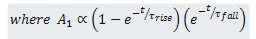
After ADC sampling and peak detection is finished, the ISR performs FM synthesis, which includes synthesis of a simple sine-based tone, shaping of the tone, new note detection, and 8-bit sound sample output. In every ISR execution, this process begins by increasing or decreasing the amplitude of the entire audio signal according to an exponential rise and fall in order to shape the note. The two envelopes, a rise and a fall, are each shifted by 8 to scale their product to an int size and they are multiplied to create the final whole-note envelope “amp_main.” Before calculations continue, the ISR checks to see if main() has set the variable “pluck,” which would signal that a new frequency has been chosen and DDS variables should be reset to recreate the transient sounds of an instrument beginning to play a note. If the note is new, then pluck is reset, all decaying amplitude values are reset to a predefined maximum, rising amplitude values are set to 0, and accumulator values which index sineTable as described below are reset so that frequencies start from a common phase, true to physical sounds.
The FM sine phase component and the overall sine-based sound output are calculated by increasing large accumulator variables “acc_fm1” and “acc_main1” by by constant values “inc_fm1” and “inc_main1,” respectively, where these constants are chosen in main() so that they cause the accumulators to overflow after an average time interval equal to the desired sound sine period. The most significant 8 bytes in each accumulator are extracted and used to find the next time sample by referencing “sineTable,” an array of length 256 whose values vary as one period of a sine wave. Only inc_fm1 is used to increase acc_fm1 and thereby determine the sine table index of “fm1,” the FM phase component of the main frequency; in contrast, acc_main1 is increased both by its accumulator and by fm1, scaled by its time decay amp_fm1, which is shifted by a preset amount “depth_fm1” to scale the overall contribution of the FM component to the digital synthesis. These calculations can then produce the sound output by finding the accumulated sineTable values given by the increments in acc_main1, scaling the result by overall amplitude amp_main, and adding an offset of 128 (i.e., 2.5V; mid-range of the output voltage). This 8-bit result is written bitwise to Port C and routed to the DAC. Lastly, the ISR increments the timing and tracking variables beatct, time, and chan and triggers a new ADC conversion on the appropriate channel if needed.
MainOur Main function is predominantly used to determine which song will be played, which note will be played, and song manipulations once a peak or fall has been detected. At the beginning of the main function, the function initialize is called and then main enters its while loop where it remains. In the while loop, the function first manipulates aspects of the songs based on a peak detections. Then, the function checks to see if the beat count (beatct) is greater than beat. Beat is hard coded to 1600 initially. When beatct is greater than beat, it is time for a new note to be played.
There are three various sound manipulations that occur in the Peak Detection portion of Main. If a peak in channel 1 is found and the flag, print1, is set, the volume variable is increased by 2. This will cause the sound output to increase in volume. If there is a fall detected in channel 1 and the flag, print3, is set, the volume variable is decreased by 2. This will allow the sound output to decrease in volume. When a peak is detected in channel 2, the print2 flag is set and the speed of the song is changed. The vector, beats, holds three different speeds, 800, 1600, and 3200, which correspond to a fast, medium, and slow speed respectively. The index b is incremented and allows a new speed in the beats vector to be assigned to the variable beat. The variables beat and ch1_vol are printed to the user in the UART so that the user knows which variables are changing and it aids in changing the speed and volume to desired levels.
The variable that determines which song to be played is notesnum. By pushing the pushbutton, notesnum is updated and the song will change to one of three songs. At the end of Main, if the timing condition to sense if the pushbutton has been pressed is satisfied, the pushbutton is debounced, and notesnum is changed. There are 3 song vectors that hold the corresponding frequencies to the song; notes1[16], notes2[24], and notes3[32]. The vectors correspond to sound clips from the Michael Jackson songs “Beat It”, “The Way You Make Me Feel”, and “Billie Jean” respectively. If notesnum is equal to 0, “Beat It” will play. If notesnum is equal to 1, “The Way You Make Me Feel” will play and “Billie Jean” plays when notesnum is equal to 2. Each song vector has an index and that index is incremented with each new beat. Once the index reaches the end on the vector, the index is reset to zero and the first frequency in the vector is assigned.
For each new beat, we also keep track of the last frequency played. The variable Pluck being reset to one is conditioned on the new frequency and the last frequency not being equal to one another. If they are equal, we don't want two notes of the same frequency that should appear to be one note longer in length, to have two rises and two decays. Thus, pluck is not set to one when the last frequency and new frequency are equal. There are also, print statements between inc_main and pluck begin reset which provides a delay that we have not been able to recreate using the delay function. Finally, the variable inc_main1 is assigned using the frequency from the song vectors. We print to the UART the value of inc_main1 to ensure correct values.
Debounce
The short helper method “debounce()” is called by main() approximately every 250 ISR executions, i.e., every 32 milliseconds. It implements a simple state machine tracked in a variable “PushState” in order to check the pushbutton for song change commands from the user and change the song promptly, exactly once, when a peak is detected. It first checks the value of the pushbutton input, Pin C.1, by comparing the entire logic value of Port C with 0x02, which indicates a high value of Pin C.1 only. This comparison will read that Port C and the comparison value are different when the button is pushed because the C.1 pull-up resistor is set, pulling the pin to Vcc except when it is shorted to ground by the pushbutton. The default, unpressed state of the state machine is titled “Release”; this state simply transitions to itself when the port value is high and routes to an intermediate state titled “Debounce” when a low value of pin C.1 is detected and a button push is inferred. “Debounce” will transition to itself if the port immediately returns to a high value because these quick changes are interpreted as switch “bouncing,” but when a zero value is detected again, it will transition to the state “StillPushed.” The StillPushed state changes the song via the “notesnum” value only the first time the state is reached after Debounce. The state machine remains at StillPushed as long as Pin C.1 is held low and transitions to the state “DebounceRelease” as soon as the pin comparison with 0x02 becomes nonzero again, indicating that the button is fully or partially released. DebounceRelease transitions to itself if Pin C.1 is read as low again and routes back to the Release state if the port is read as high again.
This state machine setup only requires that the port pin remain at its changed value for two consecutive debounce() executions before the new value is accepted as constant. Theoretically, this design would cause the program to interpret multiple button pushes if We believe this situation is unlikely because two debounce() executions take nearly 64 milliseconds, a very long time for bouncing due to human reaction, and the pushbutton consistently toggled correctly during testing.
Initialize
In initialize, we first set PortB to an output port for the DAC. We turn on timer 2 overflow with a prescaler of 8. The ADC was initialized, as well as port C.0 and C.2 as outputs, and C.1 as having a connected pull up resistor. The UART was initialized. Song variables were set to initial values as well as sound variables.
Considering the total range (2^16) of the accumulator which is increased by inc_main1 in each ISR execution so that it overflows once per period and using the ISR execution rate found above, the sine table increment required to produce a frequency is given by:
Instructions are given to the user for a user-friendly experience. We outline what our project does, and how you can manipulate the speed and volume. A 4 second delay is included so that the user has time to read the instructions. Finally, the state machine pushstate is initialized as well as the sine table.
UART Application
Upon turning on the Mega1284, the UART displays a set of directions on how to operate the system. These messages would include information about the system state as it starts, accepts input, plays notes, and turns off. The UART may also be used as an aid to view volume and frequency values as they are changed.
Software Testing and Debugging
We debugged much of our smaller software bugs by making use of flags and printing statements to the UART to test our code. If we wanted to see if the program was entering a loop or a particular area, we would print a statement to the UART so show that it was making it to that portion of the code. By printing variables and flags, we were able to detect problem areas and miss calculations.
The debugging process included several important changes to the method of detecting ADC signal peaks. Firstly, the threshold detection scheme ultimately used replaced an original detection scheme where the program detected a peak when the signal increased by a specific voltage amount over a specific length of time and additional voltage-based flags were set and reset in order to prevent a peak with a long upward ramp phase from being detected twice. The original scheme was chosen partly to account for users having different average signal levels without directly measuring that average value. The average measuring and threshold-based peak detection were added later in order to eliminate the complex flag system in the original detection scheme and better account for different shapes of peaks.Over the course of modifying previously written code for use in this project, we encountered some minor challenges adding new functionalities around preexisting code functions. Necessary variables often had to be set in other places or changed from their previous forms. For example, the variable “increment” previously used to traverse the sine wave table for digital synthesis conflicted with the name of the variable that served the same function in FM synthesis code. The variable also had to be parameterized to change based upon the changing frequency value used, whereas previous applications simply hard-coded the value. Another issue encountered in modifying existing code is shifting values; for example, a version of a sine table lookup from previous code shifted the resulting value right by 7, whereas in our code, the sine table contained much less precise values and such a large low-precision shift attenuated the sine too much for it to be heard. These and many other name-related changes were made retroactively as pre-written code was further developed.
We noticed that the ISR was very sensitive to timing, especially with UART printing. UART printing would sometimes throws off the ISR timing and skew DAC output waveforms. Sometimes that printing problems were only induced because of where they were in the ISR. We did not initially suspect certain problematic print statements because when the code was only slightly different (and often only different in another method) they executed correctly without interfering with the rest of the program. Another extremely time-sensitive feature of the ISR is modulating the amplitude of the digitally synthesized sound. The sound output would appear normal, sound distorted but similar to the goal output, or not be produced at all when minor changes were made to other portions of the code. Ultimately, it was found that in the process of switching notes after a beat, a very long delay is required after the frequency is changed and before the note amplitude is “plucked” to initial values of the exponential rise and fall. We suspect that this change was necessary because the ISR “pluck” occurred before frequency parameters were changed completely, so new energy was suddenly added to an old, decayed tone and the frequency was changed mid-tone shape shortly after, causing the tone to be heard as distorted.
For some time after the sensor armband input was first integrated into the code, there appeared to be a very long delay between movement signals seen at ADC channel 1 and the corresponding response from the program. The delay was sometimes as large as several seconds, which is greater than the time span over which the ADC vectors are designed to hold sample information, and it was difficult to determine ways that the response could be stalled by more than one ADC value set cycle. It was then found that a flag indicating that the current peak had already been addressed and should not be processed again was not being returned to its original value when the signal reached a level such that it should return. This lapse occurred because the flag was contingent on the sample value index q, which was being used to index the most recent sample, but q had in fact moved past that sample to index the next one not yet taken. We suspect that sensor signals took so long to appear because up to an entire cycle was required for q to overflow and return to the value saved at index q-1 for the flag to be set and peak detection to run, and after that, more time was required to detect fluctuations large enough to be interpreted as a peak. Simply changing the q indexing scheme as described in “Software” fixed the problem. This bug was particularly elusive and it is still not completely clear why the program executed in the way described before the bug was fixed. In general, our code involves many detailed indexing operations and small inconsistencies like this one are easy to miss.
During software testing, we were trying to solve what appeared to be an ADC input problem. When we would input a filtered phototransistor output to A1 of the ADC, with hopes to read A1, channel 1 and A2, channel 2, we would get ADC values for both channel 1 and 2. We were looking for ADC values for channel 1 and for channel 2 to be zero. When we would put a filtered input to A2 and not A1, we would get ADC values for both channel 1 and 2 as well even though we expected channel 1 to be zero. Both signals appeared to be similar and to follow each other. Through discussion and testing, we realized that if we are reading a pin that had no input, but it next to a pin that is being read that has an input, the pin with no input will read similar values to the pin with input due to AC coupling. The pin without the input would need to be grounded to not have an ADC value.Lastly, we dealt with a recurring issue of the microcontroller continually resetting itself during at some times and not others when none of the code was changed. Throughout the coding process, it would go through periods of several minutes where it would continually reset and not execute the program, and then after being turned off for as little as 30 seconds and turned back on, the programmer would operate correctly. We did not determine a cause and solution to this problem because it appeared only rarely for any given implementation of the code, but when it did appear, it prevented debugging for as much as 20 minutes at a time.
Results
In this case, the most significant product safety requirement is to protect the user from electrical contact with powered, conductive parts of the circuit, which may result in shock. This condition is enforced by preventing contact between the user and the powered portions of the device. The user will not contact any conductive portion of the circuit during use of the sensor armband; his or her arm may only touch the plastic insulator housing of the phototransistors and LEDs and the foam in which they are embedded. All wires between the on-board circuit and the devices embedded in this sensor are insulated and their junctions are protected using heat-shrink insulation. The sensor is connected to the filter and MCU circuit board using two sets of connectors, each composed of a short single row of pins, and these connectors are semi-permanently attached to a socket using electrical insulation tape to secure the sensor during arm movement and increase electrical isolation between the circuit and the user. This design was also found to be safe and well-isolated from other electrical systems because the device is not designed to emit any electromagnetic signals and it has been used heavily in the presence of many other electronic systems without any perceptible interference in any of the devices, including computers, phones, and other microcontroller-based systems.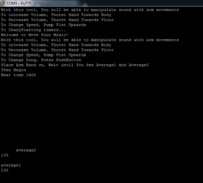
Increasing the ability of physically handicapped individuals to use technology is an explicit original motivation for this project. The armband phototransistor sensors can detect the movement of specific body parts directly or simply detect movement of muscles that aim to move a certain body part without detecting the movement of the limb itself, suggesting that an individual who has partly or wholly lost function of that part may control this device using the same muscle groups. The sensors will also read any sufficiently large muscle movement nearby, including hand, leg, facial, or shoulder movements. Although the sensor was designed and demonstrated for use with arm and hand movements, the user may have it read movements of whatever section of the body he or she can control best and intuitively adjust those movements and trigger the device as intended. The armband is adjustable for various arm sizes to fit any user snugly without discomfort. (as shown below? waveforms of other body part recordings?) Therefore, we expect that usability for a wide range of users will be a particular strength of this device.
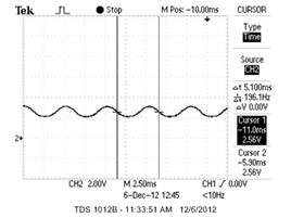
Beat It – Note Frequency |
|
Expected Freq: 196hz |
Expected Freq: 329.6hz |
Measured Freq: 200hz |
Measured Freq: 333.3hz |
Percent Error: 2.04% |
Percent Error: 1.12% |
|
|
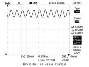
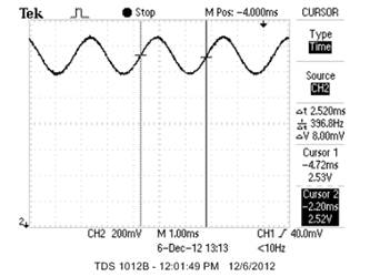
The Way You Make Me Feel– Note Frequency |
|
Expected Freq: 440hz |
Expected Freq: 392hz |
Measured Freq: 434.8hz |
Measured Freq: 396.8hz |
Percent Error: 1.18% |
Percent Error: 1.22% |
|
|
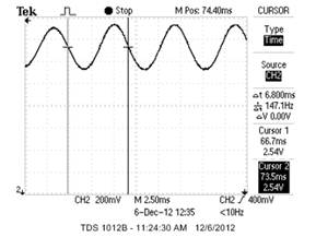
Billie Jean– Note Frequency |
|
Expected Freq: 146.8hz |
Expected Freq:196hz |
Measured Freq: 147.1hz |
Measured Freq: 196.1hz |
Percent Error: .20% |
Percent Error: .05% |
|
|
Our results show that the music frequency stays very true to what was programmed. On average, the percent error between measured frequency and programmed frequency was less than 2%.
Peak for ADC Chan1 |
Fall for ADC Chan1 |
Peak for ADC Chan2 |
|
|
|
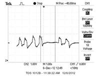
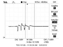
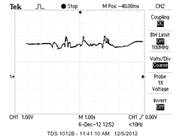
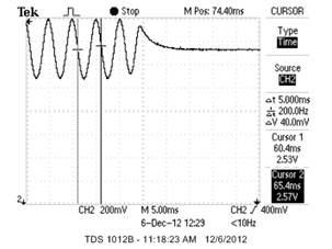
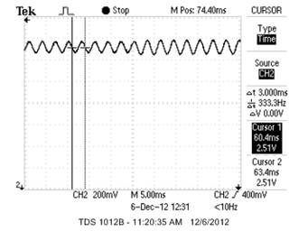
The above pictures show the output of the phototransistor signals based on various movements. In this experiment we used an upward wrist thrust towards to body to create a peak for ADC channel1, a downward wrist thrust away from the body to create a fall for ADC channel 1, and a fist pump to create peak in ADC channel 2.
Conclusions
Design Analysis and Possible Improvements
During our initial brainstorming sessions, we acknowledged that we did not know what type of results we were going to receive from the phototransistor. Thus, we proposed several different options. Initially, we hoped to be distinguished finger movements based on phototransistor outputs. We knew that if we weren’t about to pick up such a small signal for finger movements, that we would move on the detecting muscle movements in larger muscle groups. We expected to at least get significant signals from larger muscle groups. We were not about to distinguish finger movements so we moved our focus to larger muscle groups and we were able to get the results we expected. Thus, our armband and filtering system met our minimum expectations and proved to be very reliable.
Currently, we do not have a perfect success rate at detected every peak and fall from channel 1 and channel 2. We expected to have around a 85% success rate with an individual that gives a strong signal. We have met our expectation in terms of our success rate for wrist movements but we did not make our expectation for our success in fist pumps. We were still not able to detect as many peaks due to fist pumps as we had initially hoped. This problem may be improved by adding a means to prevent change to the volume whenever an arm pump is detected. Because wrist movements are detected much more easily than arm pumps, large volume changes sometimes occur when the user makes large arm pumps, interfering with the user's ability to compensate the program's lack of response with larger arm movements. Preventing these volume changes during arm movement would not change the inherent problem that the volume changes occur, but it would allow the user to control the device with arm signals more easily.
We set out to program three different songs and the sound from the clips in ideal conditions exceed our expectations. We stayed true to recognizable Michael Jacksons songs to appeal to a wide audience of various age groups.
There were numerous other things we would have liked to to implement if we had more time. First, we would have liked to include true FM modulation, which would allow for fundamentally different-sounding waveforms and switching between simulated “instruments.” This would have allowed the notes to be shaped in a rise and decay fashion. Also, FM would have allowed us to change the instrument that was playing the sound. We wanted to link a specific movement and output pattern with changing the instrument playing.
The quality of the sounds emitted could definitely be improved. They sound clearest when ch1_vol is equal to 8 and the speed is at 1600. When the ch1_vol transitions to 6, 4, 2, and 0, the sound becomes increasingly distorted and grainy. You are still able to hear the right frequencies, but the quality of sound is lessened. Changing the speed didn’t distort the sound but it noticeably made the notes sound shorter and cut-off.We only set out to program the frequencies for three songs, but having more songs to rotate through would have given the sound even more variety. We picked songs that matched the medium speed beat which limited our choices a bit. We discussed having a 2-D vector for each song that contained both the frequency of each not but also its duration. This would have allowed for more song variation and another interesting aspect to the programmed songs.
Conformation to Standards
Aside from broad safety standards, most of which are designed for higher-hazard devices, we have not found industry standards directly applicable to our design. As specified earlier, the user of this device is completely electrically isolated from the MCU and wall circuit when he or she simply wears the armband. We expect that any possible electrical hazards will occur when the user touches the custom-soldered hardware or the wall supply. The packaging of this circuit was not designed for consumer handling; if it were to be sold to consumers, it should have physically and electrically protective casing in conformance with IEC 60529 and similar electrical casing standards, though most such standards only explicitly address high-voltage devices. Electrical hazards may be reduced further by powering the MCU from a 9V battery instead of a stepped-down 120V wall supply.
We also take into consideration the OSHA Nonionizing Radiation Standard with attention to infrared radiation. Nonionzing Radiation can be a health risk to those individuals exposed when radiation is not properly controlled. An individual can absorb infrared radiation through their eyes and skin and sense it as heat. The rule of thumb for designing products with non-ionizing (light, RF, etc.) raidation is keeping radiation levels below 10kW per square centimeter. Considering the voltage drop across the LEDs and the approximate current through the sensor device, and assuming that light emitted by one of the four LEDs covers one square centimeter, our design does not meet this standard:
![]()
However, by reducing the current to the level below, the standard radiation level would easily be met.
![]()
This current reduction could be made by increasing the value of the LED resistors. Decreased emission may decrease detection levels, but we expect that detection would still be good enough to operate this project. For routine use, using a resistor around 468.75 ohms would meet the standard and allow for safe usage. Note that using this rule for IR radiation is very conservative considering that it is about 1/10th the sun's IR radiation, which humans are exposed to daily, and considering that IR radiation is much less hazardous than other forms of non-ionizing radiation to which this standard applies, such as UV.
Intellectual property considerations
The main program code “finalproject.c” is based upon the outline of code used by the designers of this device for ECE 4760 Lab 2 to build a cricket call generator; this code was originally based upon a program outline written by Bruce Land. As a result, several parts of the final program code may be attributed to him, especially in defining variables and initializing the program. The FM synthesis method used here is also adapted from his code used in “FM_synth_1.c,” a single FM modulator example provided in the ECE 4760 online course materials. The spike detection method used by this program was adapted from the ECE 4760 course material, which originally presented the method for use in Lab 3 to build an oscilloscope. The additional source code files “uart.c” and “uart.h,” which were used heavily for debugging (and help create user information displays), are programs written by Joerg Wunsch and modified by Bruce Land without modification by the designers of this project; the files have been released into the common domain via a “beer-ware license” notice included in the code. No previously written code used in this project is subject to copyright law that us, as ECE 4760 students and members of the general public, from using it.
We didn’t reverse engineer a design to build this project. We first started will trying to find a clear output signal from the phototransistors which led to the filtering system. Other additions were made throughout the project to obtain our end goals. There were no non-disclosure agreements involved to get parts, nor patent or trademark issues. Most of the parts and objects we used came from the lab. There are no patent opportunities for our project. We have simply combined existing technologies to create something fun and cool which could lead to publishing opportunities, most likely in non-academic circuit or hobby publications. The theory behind our project to use large muscle groups to control other things could lead to more applications.
Ethical Considerations
Our design process in this project has upheld all points in the IEEE Code of Ethics that govern actions during the general design process, including fair treatment of people of all racial, religious, national, and other unique individual backgrounds; honest and constructive criticism of colleagues’ work, both between colleagues regarding their separate design projects for the course and between the designers of this project regarding individual design work; and assistance of colleagues in professional development and fair, ethical course-wide behavior in completing this series of projects. Also according to these standards, this document strives to acknowledge the assistance of instructors, teaching assistants, colleagues, and external sources in completing this project. Issues of bribery and conflicts of interest inherent to this product itself did not arise during design. In addition, the course policy supports conformation with all IEEE Code of Ethics standards, especially through improving students’ and users’ understanding of technology and its implications and through enhancing students’ technical competence under close supervision by technically competent instructors.
One of the most important ethical points in our project is the need to maintain the safety of the user. This requirement is best described by the IEEE Code of Ethics points which require avoidance of endangering others and require the engineer
“to accept responsibility in making decisions consistent with the safety, health, and welfare of the public, and to disclose promptly factors that might endanger the public or the environment….” (Governance 7.8, IEEE Code of Ethics)
Throughout this project, the designers have strived to make the user interface of this device as safe as reasonably possible. The sensor armband, the main physical user interface, provides thorough electrical isolation between the sensor circuit and the user, as described above. However, in order to clarify safety requirements and prevent misinterpretations of how the device may be used safely, the user should be provided with clear written or verbal instructions in safe use. One important instruction is that in order to avoid shock or static build-up and discharge, the sensor should be connected and its connector secured before the device is powered on.Consumer information may also be used to fulfill an additional IEEE Code of Ethics requirement, a fully honest and unbiased disclosure of the capabilities and limitations of the device. For example, if this product were purchased, the user should receive documentation which clarifies that this device is not intended as a medical device and should not be used in safety-critical applications, along with any other restrictions relevant to the final product.
Legal considerations
Aside from compliance with intellectual property laws, we do not anticipate that this device is subject to special legal considerations.
Appendix
Comment Code Listing
//Final Project ECE 4760, Cornell University
//Erica Barnett, Mary Galanko
//Mega644 version
#include <inttypes.h>
#include <avr/io.h>
#include <avr/interrupt.h>
//Clock frequency
#define F_CPU 16000000UL
#include <util/delay.h>
#include <stdio.h>
#include <math.h> // for sine
//Headers necessary for LCD operation
#include <avr/pgmspace.h>
#include <stdlib.h>
#include <string.h>
#include "uart.h"
// UART file descriptor
//putchar and getchar are in uart.c
FILE uart_str = FDEV_SETUP_STREAM(uart_putchar, uart_getchar, _FDEV_SETUP_RW);
//I like these
#define begin {
#define end }
//Variable sound that holds sign wave samples
volatile char sound;
// Variables used to compute the avearge sample for each person
volatile unsigned long total = 0;
volatile unsigned long total2 = 0;
unsigned char average, average2;
//State machine state names
#define Release 1
#define Debounce 2
#define StillPushed 3
#define DebounceRelease 4
#define DetectTerm 5
#define DebounceTerm 6
#define StillTerm 7
#define Done 8
//the task subroutines
void statemachine(void); //debounced button 1
void debounce(void); //handles key press to stop playing
void initialize(void); //all the usual mcu stuff
//FM synthesis
volatile unsigned int acc_main1, acc_fm1 ;
volatile unsigned char high_main1, high_fm1 ;
volatile unsigned int inc_main1, inc_fm1;
volatile signed char fm1;
volatile unsigned int time1; //counts number of ms elapsed
volatile unsigned int lasttime1; //holds a previous time1 value for comparision
volatile unsigned char ms; //countdown of 62.5kHz periods to 1 ms
volatile unsigned char lastms; //last countdown value used to generate millisecond
volatile unsigned char s_int; //syllable interval variable
volatile unsigned char level; //read from ADC
volatile unsigned int mod; //how much to change DAC output frequency
unsigned char PushState; //state machine
unsigned char startFlag; //=1 when processing a start press; =2 when song
//ready to start; =0 otherwise
unsigned char stopFlag; //=1 when processing a stop press; =0 otherwise
unsigned char maybe; //holds button press number for debouncing
volatile unsigned char last_peak1 = 0; //variable used to save last peak value from Chan1
volatile unsigned char last_peak2 = 0; //variable used to save last peak value from Chan2
volatile unsigned char last_fall = 0; //variable used to save last fall value from Chan1
volatile unsigned char peak1 = 0; //variable used for number of peak detection from Chan1
volatile unsigned char peak2 = 0; //variable used for number of peak detection from Chan2
volatile unsigned char fall = 0; //variable used for number of fall detection
volatile unsigned char print1 = 0; //variable used to flag peak1
volatile unsigned char print2 = 0; //variable used to flag peak2
volatile unsigned char print3 = 0; //variable used to flag fall
// tables for DDS
volatile signed char sineTable[256] ;
// index for sine table build
unsigned int i;
//ADC saving variables
volatile unsigned char chan;
volatile unsigned char count;
volatile unsigned char sample[4][256];// = sineTable * zero;
volatile unsigned char q; //index of ADC channel vector
volatile unsigned char first = 0;
volatile unsigned char scnd = 0;
volatile unsigned char upflag1 = 0; //1 if signal was incremented recently (peak detection flag) in Chan1
volatile unsigned char upflag2 = 0; //1 if signal was incremented recently (peak detection flag) in Chan2
volatile unsigned char downflag = 0; //1 if signal was incremented recently(fall detection flag) in Chan 1
/////Song variables
// The DDS variables
volatile unsigned char decay_fm1, decay_main, depth_fm1, rise_main ;
volatile unsigned int amp_main, amp_fm1 ;
volatile unsigned int rise_phase_main, amp_rise_main, amp_fall_main ;
#define max_amp 32767
unsigned char ch1_vol = 4;
// trigger
volatile char pluck;
// Time variables
// the volitile is needed because the time is only set in the ISR
// time counts mSec, sample counts DDS samples (62.5 KHz)
volatile unsigned int time, lasttime;
unsigned int beat = 1600; //should be about 2500 for The Way You Make Me Feel
unsigned int beats[10] ={800, 1000, 1200, 1400, 1600, 1800, 2000, 2400, 2800, 3200};
unsigned char b=0;
unsigned int beatct; //tracks ISR executions to count beat
float notes1[16] = {164.8, 164.8, 196, 246.9, 392, 329.6, 0, 329.6, 370, 0, 329.6, 293.7, 0 , 293.7, 0 , 246.9}; //notes to Beat It
float notes2[24]= {440, 0 , 440, 466.2, 0, 466.2, 523.3, 0 , 523.3, 440, 440, 0, 349.2, 0, 349.2, 392, 392, 0, 349.2, 0 , 349.2, 349.2, 0, 349.2};// notes for The Way You Make Me Feel
//float notes3[32]= {246.9, 293.7, 370, 370, 329.6, 370, 329.6, 370, 370, 293.7, 370, 370, 392, 370, 329.6, 329.6, 0, 293.7, 370, 370, 329.6, 370, 329.6, 370, 0, 370, 329.6, 370, 392, 370, 329.6, 0};// for You Rock My World
//float notes3[16]= {196, 146.8, 174.6, 196, 174.6, 146.8, 130.8, 146.8, 98, 146.8, 174.6, 196, 174.6, 146.8, 130.8, 146.8}; //notes to Billie Jean intro
float notes3[32]= {196, 196, 146.8, 0, 174.6, 0, 196, 196, 174.6, 0, 146.8, 0, 130.8, 0, 146.8, 0, 98, 98, 146.8, 0, 174.6, 0, 196, 196, 174.6, 0, 146.8, 0, 130.8, 0, 146.8, 0}; //notes to Billie Jean intro
float freq; //holds current frequency
float freq_last; // holds the last frequency
unsigned char j = 0; //holds notes1 vector index
unsigned char k = 0; //holds notes2 vector index
unsigned char l = 0; //holds notes3 vector index
unsigned char notesnum; //used to rotate between songs
unsigned char changed = 0; //tracks song change for single button push
unsigned char push; //hold read of pins
///// INFORMATION FOR UART PRINTING
int8_t sound_buffer[12]; //to print sound
int8_t level_buffer[12]; //DEBUG: print current state
/////
//**********************************************************
//timer 0
ISR (TIMER2_OVF_vect) //generates PWM and millisecond signals
begin
// Decide when to save ADC sample
if (count==10) {
if (chan==1) {
sample[1][q++] = ADCH; //saves channel 1 info at 100Hz
if (first<255) { //initial buffer at start
first++;
total = total + sample[1][q-1]; //using total for average
if(first == 255) {
average = (int) total/256; //compute average ADC value and print, use as base case for Chan1
fprintf(stdout,"average1\n\r");
sprintf(level_buffer, "%i\r\n", average);
fprintf(stdout,level_buffer);
fprintf(stdout,"\n\r");
}
}
// Condition for falling signal passed a specified threshold
else if ((sample[1][q-2]>(average-10))&&(sample[1][q-1]<(average-10))){//&&(downflag==0)&&(upflag1==0)){
//last_fall = fall;
fall = fall + 1; //keep track of the number of falls
print3= 1; // set flag to be used in Main
downflag=1; //detection flag
}
// Condition for peaking signal passed a specified threshold
else if ((sample[1][q-2]<(average+12))&&(sample[1][q-1]>(average+12))){//&&(upflag1==0)&&(downflag==0)){
//last_peak1 = peak1;
peak1 = peak1 + 1; //keep track of the number of peaks
print1= 1; // set flag to be used in Main
upflag1=1; //detection flag
}
if ((sample[1][q-1]>(average))&&(downflag==1)) {
//Signal has returned to average; reset increase flag
downflag = 0;
}
if ((sample[1][q-1]<average)&&(upflag1==1)) {
//Signal has returned to average; reset increase flag
upflag1 = 0;
}
//Reset count variable - ONLY when ADC channel is 1
count = 0;
}
else if (chan==2) {
sample[2][q] = ADCH; //saves channel 2 info at 100Hz
if (scnd<255) { //initial buffer at start
scnd++;
total2 = total2 + sample[2][q]; //using total2 for average
if(scnd == 255) {
//sprintf(sound_buffer, "%ld\r\n", total);//For Debugging Purposes
//fprintf(stdout,sound_buffer);
//fprintf(stdout,"\n\r");
average2 = (int) total2/256; //compute average2 ADC value and print, use as base case for Chan2
fprintf(stdout,"average2\n\r");
sprintf(level_buffer, "%i\r\n", average2);
fprintf(stdout,level_buffer);
fprintf(stdout,"\n\r");
}
}
// Condition for peaking signal passed a specified threshold
if ((sample[2][q-1]<(average2+15))&&(sample[2][q]>(average2+15))) {//&&(upflag2==0)){
//last_peak2 = peak2;
peak2 = peak2 + 1; //keep track of the number of peaks
print2= 1; // set flag to be used in Main
upflag2=1; //detection flag
}
if ((sample[2][q-1]<30) && (upflag2==1)) {
//Signal has significantly decreased; reset increase flag
upflag2 = 0;
}
}
}
else if (chan==1) {
count++;
}
////This block required for beat shaping
if ((time & 0x0ff) == 0) begin
//fprintf(stdout,"Change ampl\r\n"); //Condition is being entered
amp_fall_main = amp_fall_main - (amp_fall_main>>decay_main) ;
rise_phase_main = rise_phase_main - (rise_phase_main>>rise_main);
// compute exponential decay of FM depth of modulation
amp_fm1 = amp_fm1 - (amp_fm1>>decay_fm1) ;
end
////////
// form (1-exp(-t/tau)) for the attack phase
amp_rise_main = max_amp - rise_phase_main;
// product of rise and fall exponentials is the amplitude envelope
amp_main = (amp_rise_main>>8) * (amp_fall_main>>8) ;
////This block required for beat shaping////
// Init the synth
if (pluck==1) begin
amp_fall_main = max_amp;
rise_phase_main = max_amp ;
amp_rise_main = 0 ;
amp_fm1 = max_amp ;
// phase lock the synth
acc_fm1 = 0 ;
acc_main1 = 0;
pluck = 0;
end
//////////
//the FM DDR -- feeds into final DDR
acc_fm1 = acc_fm1 + inc_fm1 ;
high_fm1 = (char)(acc_fm1 >> 8) ;
fm1 = sineTable[high_fm1] ;
//the final output DDR
// phase accum = main_DDR_freq + FM_DDR * (FM amplitude)
//acc_main1 = acc_main1 + inc_main1 + ((fm1)) ;
acc_main1 = acc_main1 + (inc_main1 );//+ (fm1*(amp_fm1>>depth_fm1))) ;//depth_fm1
high_main1 = (char)(acc_main1 >> 8) ;
// output the wavefrom sample
// scale amplitude to use only high byte and shift into range
// 0 to 255
sound = 128 + (int) (((amp_main>>ch1_vol) * (int)sineTable[high_main1])>>6) ;
//sound = 128 + ((((amp_main>>8) * (int)sineTable[high_main1])>>6)) ;
//NOTE: In previous DDS unit, had to remove shift by 7
PORTB = sound;
//Increment counter to change frequencies if needed
beatct++;
time++; //increment counter used for decay & main() timing
//Increment next channel
if (chan<7) chan++;
else if (chan>=7) chan = 0;
//Choose next ADC channel as input
if (chan==1) ADMUX = 0x61; //Leave previous REFS0 and ADLAR settings
if (chan==2) ADMUX = 0x62;
_delay_us(10); //wait to settle
//Check: print ADMUX
//Trigger next ADC sample
//_delay_ms(5);
ADCSRA |= (1<<ADSC) ;
end
//**********************************************************
//Entry point and task scheduler loop
int main(void)
begin
initialize();
//main task scheduler loop
while(1)
begin
////// Peak Detection
if (print1 == 1) {
/*fprintf(stdout,"Peak1\n\r");//For Debugging Purposes
sprintf(level_buffer, "%i\r\n", peak1);
fprintf(stdout,level_buffer);
fprintf(stdout,"\n\r");*/
//PORTC^=0x04;
//Detected a peak in Chan1
if (ch1_vol<8) { // increase the volume
ch1_vol= ch1_vol + 1;
//Print Peak1ch1_vol
fprintf(stdout,"Peak Volume ");
sprintf(level_buffer, "%i\r\n", ch1_vol);
fprintf(stdout,level_buffer);
fprintf(stdout,"\n\r");
}
print1= 0; //reset flag
}
if (print2 == 1){
/*fprintf(stdout,"Peak2\n\r"); //For Debugging Purposes
sprintf(level_buffer, "%i\r\n", peak2);
fprintf(stdout,level_buffer);
fprintf(stdout,"\n\r");*/
//When change detected, toggle port...
PORTC^=0x04;
//Detected a peak in Chan2--> change beat speed
if (b==9) {
b=0;
beat = beats[b];
}
else beat = beats[++b];
//Print Beat Time
fprintf(stdout,"Beat time ");
sprintf(level_buffer, "%i\r\n", beat);
fprintf(stdout,level_buffer);
fprintf(stdout,"\n\r");
print2= 0; //reset flag
}
if (print3 == 1) {
/*fprintf(stdout,"Fall\n\r"); //For Debugging Purposes
sprintf(level_buffer, "%i\r\n", fall);
fprintf(stdout,level_buffer);
fprintf(stdout,"\n\r");*/
print3= 0;//reset flag
//Detected a fall in Chan1
if (ch1_vol>0) {
ch1_vol= ch1_vol - 1; //decrease volume
//Print Fallch1_vol
fprintf(stdout,"Fall Volume ");
sprintf(level_buffer, "%i\r\n", ch1_vol);
fprintf(stdout,level_buffer);
fprintf(stdout,"\n\r");
}
}
////// Changing Songs
if (beatct>=beat) {
beatct = 0; //reset count
// Find new frequency
//Song: Beat It
if (notesnum == 0){
if (j==15) { //reached end of notes - go back to 0
j = 0;
freq_last = freq; //remember last freq
freq = notes1[j];
}
else {
freq_last = freq; //remember last freq
freq = notes1[++j]; //move to next note
}
}
//Song: The Way You Making Me Feel
else if (notesnum == 1) {
if (k==23) { //reached end of notes - go back to 0
k = 0;
freq_last = freq; //remember last freq
freq = notes2[k];
}
else {
freq_last = freq;//remember last freq
freq = notes2[++k]; // move to next note
}
}
//Song: Billie Jean
else if (notesnum == 2){
if (l==31 ) { //reached end of notes - go back to 0
l = 0;
freq_last = freq; //remember last freq
freq = notes3[l];
}
else {
freq_last = freq; //remember last freq
freq = notes3[++l]; // move to next note
}
}
/*else if ((beatct>=(beat/2))&&(notesnum==2)) {
if (l==31 ) { //reached end of notes - go back to 0
l = 0;
freq_last = freq; //remember last freq
freq = notes3[l];
}
else {
freq_last = freq; //remember last freq
freq = notes3[++l]; // move to next note
}*/
// Calculate increment, etc. of new frequency
inc_main1 = (int)(8.389 * freq);//freq) ;
//_delay_ms(200); //Attempted to replace print statements with delay
fprintf(stdout," "); //print for time delay
fprintf(stdout," \r\n");
if (freq_last!=freq) pluck = 1;
}
////// Sense pushbutton press, debounce, and switch song
if ((time-lasttime)>=250) {
time = lasttime;
push = PINC;
debounce(); //Run state machine ~32x/sec
}
end
end ///****************!!
//*******************************
//Debouncing stop button
void debounce(void)
begin
switch (PushState)
begin
case Release:
if ((push&0x02) == 0x00) PushState = Debounce; //Pin C1 is pulled down
else PushState=Release;
break;
case Debounce:
if ((push&0x02) == 0x00) { //was push==249
fprintf(stdout,"button\r\n");
PushState=StillPushed;
}
else PushState=Debounce;
break;
case StillPushed:
if ((push&0x02) == 0x00)
begin
PushState=StillPushed;
// Change song
if ((notesnum==0)&&(changed==0)) {
j = 0;
notesnum = 1;
}
else if ((notesnum==1)&&(changed==0)) {
k = 0;
notesnum = 2;
}
else if ((notesnum==2)&&(changed==0)) {
l = 0;
notesnum = 0;
}
changed = 1; //indicates song has been changed for this push
end
else PushState=DebounceRelease;
break;
case DebounceRelease:
if ((push&0x02 == 0x00)) PushState=StillPushed;
else
begin
PushState=Release;
changed = 0;//clear flag for next button push
end
break;
end
end
//**********************************************************
//Set it all up
void initialize(void)
begin
//set up the ports
DDRB = 0xff; // PORT B is the output to DAC
TIMSK2= (1<<TOIE2); //turn on timer 2 overflow ISR
TCCR2B= (1<<CS21); //Timer 2 has prescalar of 8
// question: need to time ADC sample differently from DAC samples?
//Set up ADC
ADMUX |= ((1<<ADLAR) | (1<<REFS0)| 1); //(1<<1)); //Left adjust result; ADC1 AS INPUT
chan = 2;
//ADMUX &= 0xfe; //ADC0 AS INPUT
ADCSRA = ((1<<ADEN) | (1<< ADSC) |(1<<ADPS2)|(1<<ADPS1)|(1<<ADPS0)); //enable ADC; divide clock by
DDRC=0x05; // PORT C.0 and C.2 is an output; all others can stay inputs
PORTC=0x03;// Enable Port C.1 pull-up resistor
//init the UART -- uart_init() is in uart.c
uart_init();
stdout = stdin = stderr = &uart_str;
fprintf(stdout,"Starting timers...\n\r");
notesnum = 0; //Begin with song 1
freq = notes1[0]; //Initialize Freq to first note in song vector
pluck = 1;
// 2^16/(7812.5Hz)*freq = 8.389*freq
inc_main1 = (int)(8.389 * freq) ; //previously, for exactly 8 kHz: (int)(8.192*freq);
//Bowed string
decay_main = 5 ;
rise_main = 4 ;
inc_fm1 = (int)(8.389 * 300) ;
depth_fm1 = 8 ;
decay_fm1 = 6 ;
//initial instructions
fprintf(stdout,"Welcome to Move Your Music!\n\r");
fprintf(stdout,"With this tool, You will be able to manipulate sound with arm movements\n\r");
fprintf(stdout,"To increase Volume, Thurst Hand Towards Body \n\r");
fprintf(stdout,"To Decrease Volume, Thurst Hand Towards Floor \n\r");
fprintf(stdout,"To Change Speed, Pump Fist Upwards \n\r");
fprintf(stdout,"To Change Song, Press PushButton \n\r");
fprintf(stdout,"Place Arm Band on, Wait until You See Average1 and Average2\n\r");
fprintf(stdout,"Then Begin \n\r");
//delay to read instructions
_delay_ms(4000);
//init the state machine
PushState = Release;
// init the sine table
for (i=0; i<256; i++)
begin
sineTable[i] = (char)(127.0 * sin(6.283*((float)i)/256.0)) ;
end
sei() ;
end
Full Schematic
LED, Phototransistor and Filter System Circuit Diagram
Audio Drive Amp Circuit Diagram

Cost Details
| Description | Quantity | Unit Price | Item Total | Necessity | Comment |
| Computer speakers | 1 set | $9 | $9 | Main project | Source: http://www.newegg.com/Product/Product.aspx?Item=N82E16836121016 |
| Large solder board | 1 | $6 | $6 | Main project | |
| Breadboard | 1 | $5 | $5 | Main project | |
| Mega1284p | 1 | $5 | $5 | Main project | |
| Wires | ? | $0 | $0 | Main project | |
| Arm band: fabric, Velcro, etc | ? | $0 | $0 | Main project | In personal stock |
| Foam | 1 | $0 | $0 | Main project | in Lab |
| Cardboard | 1 | $0 | $0 | Main project | in Lab |
| Heat Shrink | - | $0 | $0 | Main project | in Lab |
| color electrical tape | - | $0 | $0 | Main project | in Lab |
| Ceramic Capacitors 22µF PN: 445-8492-ND |
12 | $0.38300 |
$4.60 | Main project | Manufacturer: TDK Corporation Ordered: DigiKey |
| Ceramic Capacitors 47µF PN: 445-4826-ND |
10 | $0.45500 | $4.55 | Main project | Manufacturer: TDK Corporation Ordered: DigiKey |
| Aluminum Capacitors 39µF PN: P11215-ND |
12 | $0.34000 |
$4.08 | Main project | Manufacturer: Panasonic Electronic Components Ordered: DigiKey |
| Target Board | 1 | $4 | $4 | Main project | Built in lab |
| 9V Power Supply | 1 | $5 | $5 | Main project |
TENTATIVE TOTALS
| Project scope | Total |
| Arm band only | $47.23 |
Task Distribution
| Mary Beth | Together | Erica |
| Debounce (software) | ISR (software) | 1st and Final Armband productions (hardware) |
| Audio Drive Amp Design and Production (hardware) | Main (software) | Final Filtering System Production (Hardware) |
| Testing and Debugging (Hardware and Software) | Initialize (Software) | Testing and Debugging (Hardware and Software) |
| Armbands design (hardware) | ||
| Filtering System design (hardware) | ||
| Filtering System Production on breadboard (hardware) | ||
| DAC (hardware) | ||
| Testing and Debugging (Hardware and Software) | ||
| Final Report/Webpage |
Unfortunately for the suggested outline and symmetry of this chart, almost every effort on both the hardware and software was a team effort. We apologize for any inconveniences this may have caused.
References Used
This sections provides links to various references that we have used in the design process for our final project.
Datasheets
Background Info
- Note Frequency Chart
- Sallen-Key topology description
- Related Patents
- FM synthesis
- IEEE Code of Ethics
- Nonionizing Radiation Standard
- Beat It
- The Way You Make Me Feel
- Billie Jean
Class Link
Pictures
- Logitech speakers used
- Sallen-Key Lowpass
- Speaker connection
- Color Music Notes
- Picture of LM353N
- DAC Resistor Network
Vendor Links
Acknowledgements
First and foremost, we would like to thank our lecturer, Dr. Bruce Land, for his patient and thorough assistance with our final project and with the course work as a whole. He provided us with additional assistance in developing our phototransistor control scheme, which was based upon sensing techniques he developed personally. We like to thank the course TAs for the important help each of them provided as we improved our project, with special thanks to our lab TA, Terry Kim, for the extensive time, energy, and laughs she contributed during our work in the course. Finally, we want to thank our classmate Tian Guo (the “BIU!” guy!) for helping us debug our lab and project work on his own time.
We acknolwedge the orignial creators of this website template, previous ECE 4760 students Patrick Dear and Mark Bunney.