"An electronic multi-instrument player on the touchscreen with record/replay and tutorial functions"
In our final project, we designed an electronic multifunction instrument with a LCD touch screen and a microphone. The user can play three kinds of instruments on it -- xylophone, flute and piano. Each instrument has a different interface and timbre. The piano part has a record/replay function which can echo the song previously played on it. In addition, the system has another function to teach the user to play two pieces of songs already stored in the memory.
The LCD touch screen will display these three kinds of instruments -- the keyboard of xylophone and piano and the holes of flute. User just presses on the keyboard to play the music. For the flute, the user need to press on the screen while blowing to the microphone, which simulates a real organ-like instrument. It also has record/replay and teaching functions.
The idea of this project came from some apps on the smart phone. It is very cool and popular to play a virtual instrument on the mobile phone, such as a guitar or a piano. People can take them everywhere and play on it whenever they want. With some knowledge about sound synthesis acquired in the class, we decided to build the electronic multifunction instrument in our project. Meanwhile, this project will also provide ECE4760 course a library for initializing LCD touch screens for reference. It also gives us experience in utilizing a set of devices which is popular in modern devices.
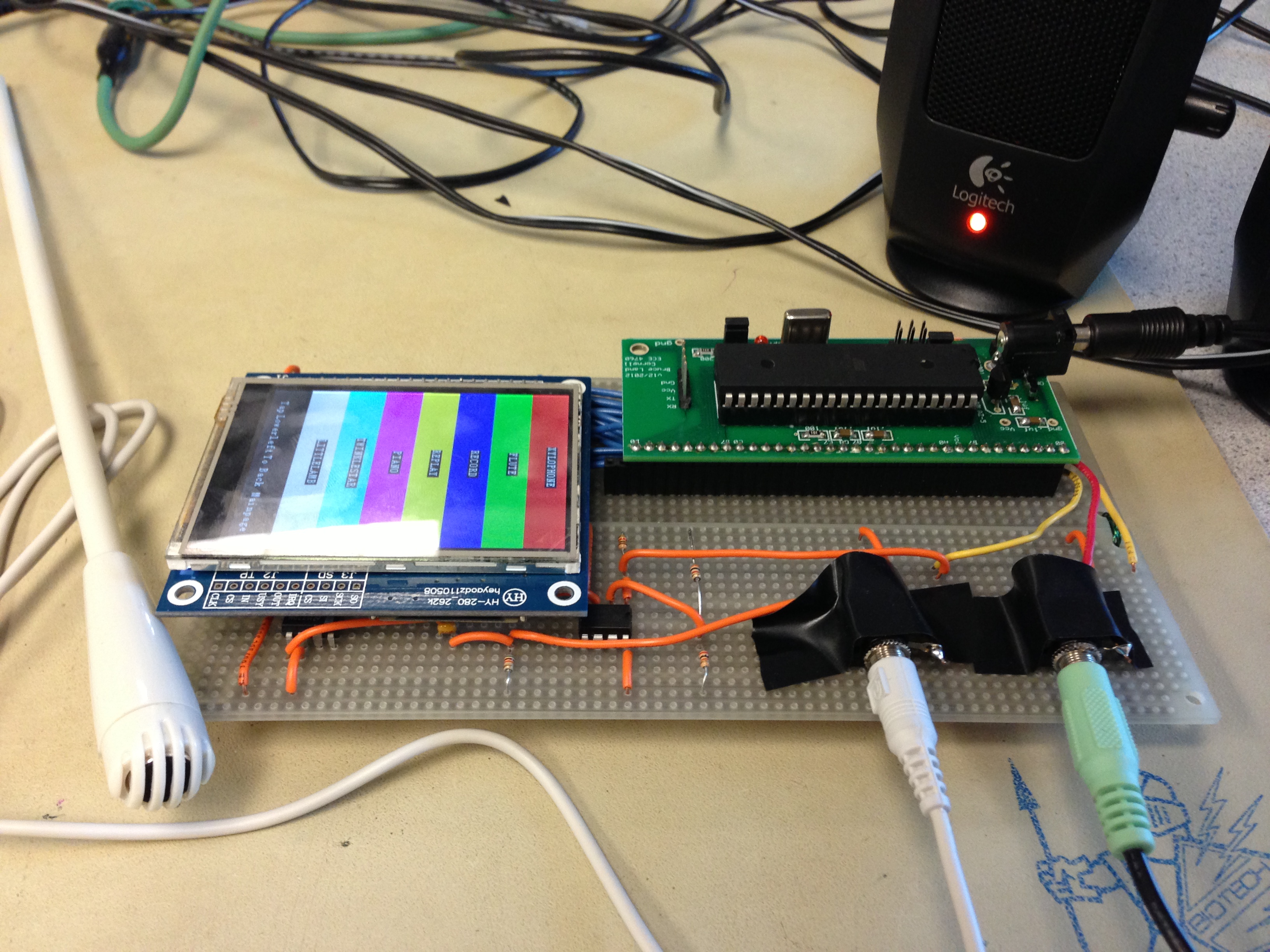
The Electronic Multifunction Instrument
High Level Design
Rationale
It is quite meaningful for us to do this project. On the one hand, with the increasing popularity of touch-screen mobile phones and tablet PCs, touch screen becomes more and more important in our lives. It is much more convenient and flexible than the traditional keyboard. On the other hand, even though actual instruments have better tunes and player experience, they are always ponderous and hard to move or carry around. So it is very useful for us to play music only with a tiny and light box containing a touch screen and some electrical boards. Since we already owned a board with a touch screen LCD and relevant control chips on it, we came with the idea to implement a play-music function to the touch screen and also added some other functions talked above.
Logical structure
At the high level, our project mainly consists of four parts: the mega1284 microcontroller, the LCD touch screen, the microphone and the speaker. Mega1284 is the main control part. When user presses on the screen or blows at the microphone, the signal will be sent to the MCU and some certain sound will be played from the speaker. Also the MCU will control what is shown on the LCD screen and the state mode, based on the screen interrupt.
The connection between MCU and touch screen needs a LCD driver and an ADC chip. They are already on the touch screen board. An opamp is needed for the amplification of the input signal from the microphone. Then the MCU outputs the sound via an RC filter circuit. The high-level structure diagram of the system is shown below.
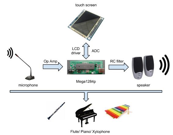
High-level structure diagram of the system.
Hardware/Software tradeoffs
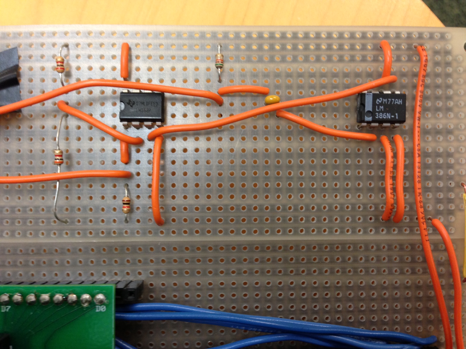
The hardware part of our project is not very complex. We already owned the touch screen and soldered our own Mega1284 prototype board. The LCD touch screen consists of two chips, ILI9325 LCD control chip and XPT2046 touch panel controller chip. The speaker and microphone are available in the lab. The only tricky thing is to convert the blowing signal to a continuous high-level voltage signal. We used two opamp chips to meet this requirement -- LM386 and LM358, both are available in the lab. The total cost is surely under the budget.
For the software part, we thought it is pretty hard for the sound synthesis. So we tried both the FM and additive synthesis methods to get the idea effect. We also used the matlab program for the sound synthesis before implementing to the C code. For the touch screen part, we distribute the function into several modes. Each part we used some judgment and other codes to realize the function in the certain mode. It is not too hard to program and can be reliable.
Standards and Patents
Our design uses the SPI(serial peripheral interface) between the communication of touchpanel and AVR. Devices communicate in master/slave mode where the master device initiates the data frame. One patent is used in our design of FM synthesis algorithm. US3794748, Method of synthesizing a musical sound, by John M.Chowning in 1974, is where FM synthesis comes from. It is a research result of Stanford University.
Hardware Design and Implementation
Hardware Overview
From the high-level discussed above, our hardware consists of four parts, which include the LCD touch screen, the low pass filter circuit, the microphone input circuit and the Mega1284 prototype board. Below we will discuss each part separately.
LCD touch screen
The LCD touch screen we use contains of 2 parts, a 2.8 " TFT LCD screen and the touch panel. The TFT LCD use the control chip, ILI9325, while the touch panel uses the Analog Device XPT2046 touch screen controller. (Figure of LCD touch screen). One of the reason we use LCD touch screen is that we can provide ECE4760 class some library for initializing LCD screen and touch panel.
ILI9325 is a 262,144-color one-chip SoC driver for a-TFT liquid crystal display with resolution of 240RGBx320 dots, comprising a 720-channel source driver, a 320-channel gate driver, 172,800 bytes RAM for graphic data of 240RGBx320 dots, and power supply circuit. By using this LCD, we can avoid some problem in our lab3, digital oscilloscope, that we need always refreshing the screen. The existence of GRAM in ILI9325 helps us to save the time in refreshing the screen. When we need to change what will be shown on screen, we just need to write the GRAM which replace the dots on the LCD.
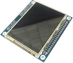
Touchscreen
Low pass filter and Speaker wiring
We also need a lowpass circuit to filter the PWM output. We decide to get RC= 1/10000 and set R= 5000ohm, which is lower than speaker input 10kohm. So C= 20nf. Actually we choose the 5.1kohm resistor and 20nf capacitor to build this circuit for the real value of the components. The INPUT is connected to the output of the PWM which is pin B.3 (OC0A). The OUTPUT is connected to the channel 1 in the plug of audio. The audio is shown below. Ground will be connected to the GND port on the board.
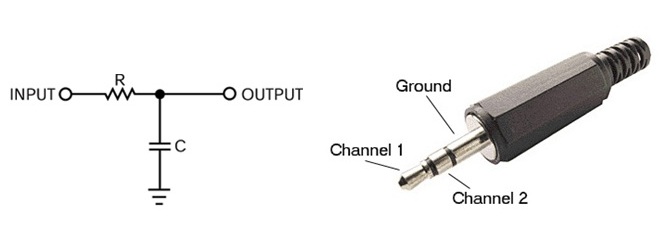
lowpass filter and audio plug
Microphone input circuit
The microphone is used to capture the airflow from the player's mouse to simulate the flute. According to the structure of the microphone, the sensor in the microphone will vibrate due to the frequency of the voice and so cause the change of the value of the capacitor in it. Thus the normal output of the microphone is like an irregular vibration wave. However, the purpose of the using of microphone in our project is only to detect the blowing wind, not the frequency. So we need to convert the output of the microphone to a high-voltage level when blowing and low-voltage level with no blowing. The circuit we designed for the input of the microphone is like this.
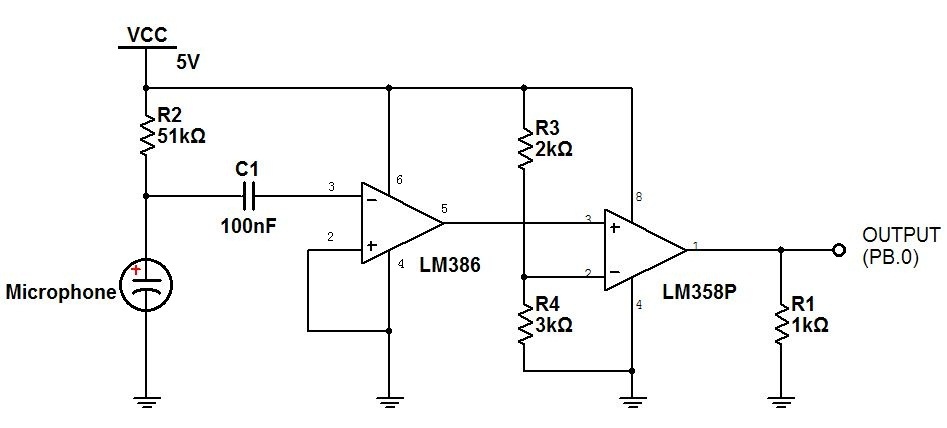
microphone input circuit
When we blow to the microphone, the voltage on C1 will vibrate. Since the amplitude of the vibration is much smaller than the static voltage, we need the capacitor C1 to separate the AC part and then use the LM386 (audio amplifier chip) to amplify the wave. We do not connect pin1 and pin8 on the LM386, so the amplification gain is 20. Then we use the oscilloscope to detect the output of LM386 and found it is between 1 to 3.5 volt with the static value equals to 2.2 volt. So we use the LM358 (comparator chip) and R3 and R4 to set the negative input as 2.7 volt( actually, the Vcc is a little smaller than 5V). So when we blow to the microphone, the output of LM386 could be greater than 2.7V and the output of LM358 will be high level, which can be detected by the microcontroller.
Note that R1 is used to make sure that the output is set low when there is no sound. Normally, R2 should be around 10kOhms. Because of the high current for the LCD touch screen. the Vcc may always been pull-down. That causes a wrong signal for the output. So we choose a big resistor with 51kOhms to limit the voltage vibration and it works. So in our flute design(below), we set a flag when we detect a high voltage. After a note is generated, we will clear the flag and wait for next high voltage of output.
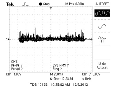
Below are the voltages of C1left, C1right, LM386 output and LM358 output.
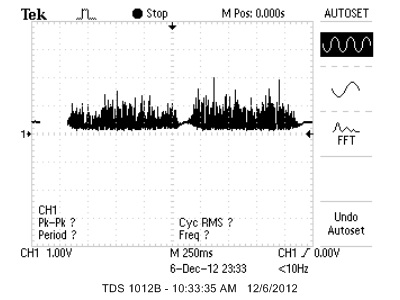
microphone direct output and input of LM386
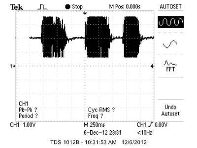
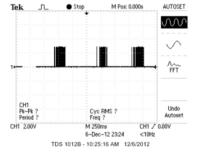
output of LM386 and output of LM358
Prototype Board
We build our own prototype board in the lab. The microcontroller and some peripheral capacitors and resistors are on it. The prototype board PCB is shown in the appendix.
Connection Board
In order to connect the prototypr with the touch screen board, we build this connection borad. The block diagram of connection is given in the appendix. The left 40-pins socket is for the prototype board and the right 20*2-pins socket is for the touch screen board. Also the low pass filter is also soldered on this board.

Conection Board
Software Design and Implementation
Overview
The most important part for the software design is the sound synthesis and the touch screen control. As described above, we devided this app into 6 modes.
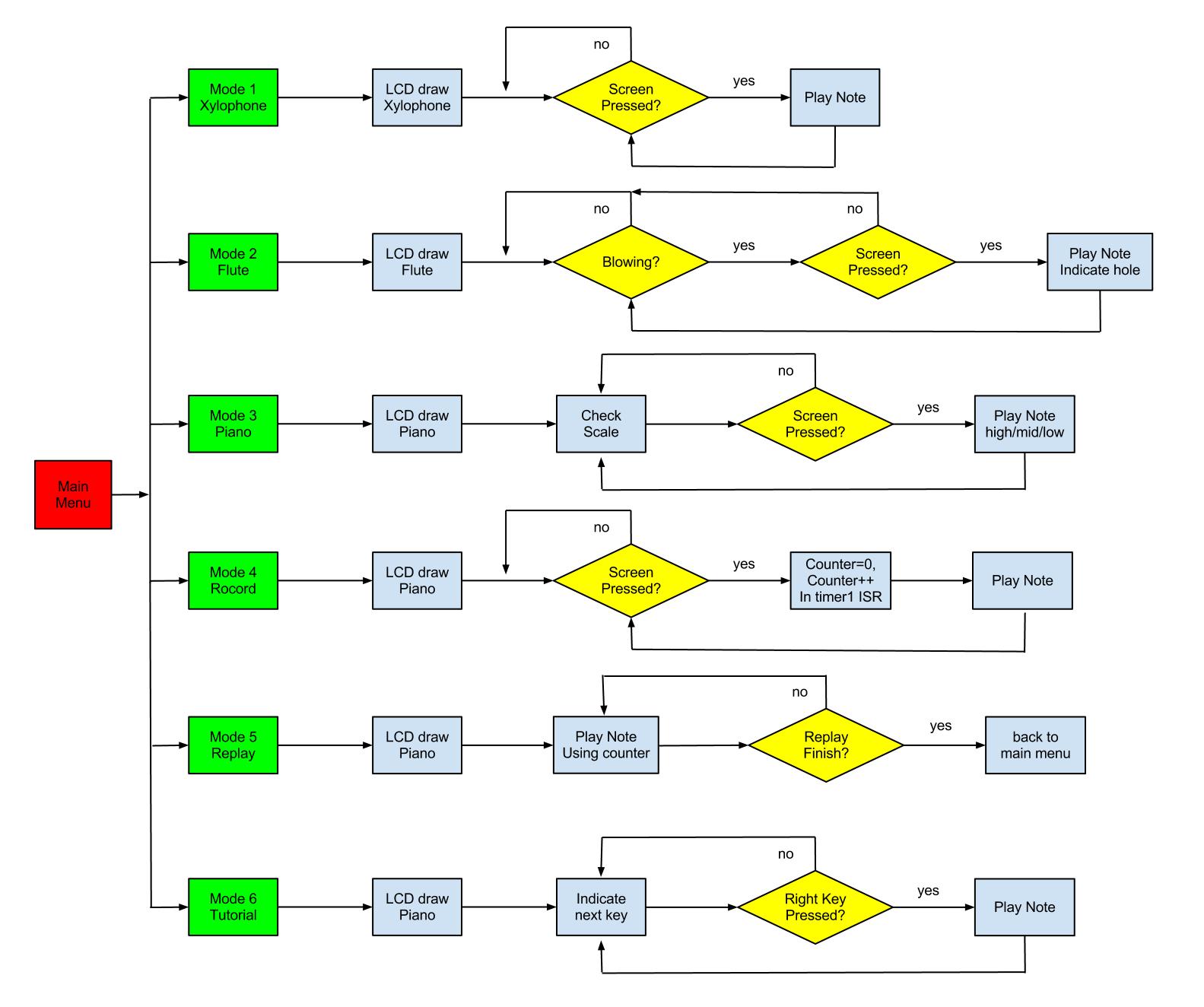
Six modes for our app
Sound Synthesis
In this project, two synthesis method are used to generate the notes of different insturments. The additive synthesis and FM synthesis are adopted. Below we will introduce the two methods.
FM synthesis
We use the FM synthesis (frequency modulation synthesis) method to produce the piano sound. By using the Fast PWM function on the microcontroller we can generate a sound with particular frequency, which was already realized in previous labs. However, this method can only get a sine wave that does not match any timbre from an instrument. In order to change the timbre of the sound, we decided to use the FM synthesis method.
The FM synthesis is a form of audio synthesis where the timbre of a simple waveform is changed by frequency modulating it with a modulating that is also the audio range, resulting in a more complex waveform and a different sounding tone. It is developed by John Chowning at Stanford University in 1967-68. Bessel functions represented the mathematical principle of this method. The formula for elementary FM synthesis is given by

where (Ac, fc) specify the carrier sinusoid and (Am, fm) specify the modulator sinusoid. In order to get the real wave of the sound, the changes of Ac and Am with time should be like the following. So Ac and Am are replaced by some math expression and the output x(t) is given by
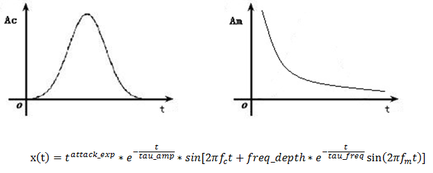
where Ac is determined by attack_exp and tau_amp and Am is determined by freq_depth and tau_freq. So the most crucial part to synthesize a piano sound is to find some good parameters for these variables, including fc.
Though it is easy to calculate the formula above in a matlab program, we need to do some improvements to the formula to implement it in a C code. First, we replace t^(attack_exp) with (1-e^(-t/(tau_att )) ). Then we let Xn equal to e^(-t/(tau_amp)) and Yn equal to (1-e^(-t/(tau_att )) ), so
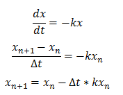
Let ∆t*k=2^(-P), so we get the code Xn+1 = Xn—(Xn>>P). It is similar to calculate for Yn. In our program for FM synthesis, we use amp_fall_main and some other variables to represent P in the timer1 compare ISR. For every 256/8000s, the program recalculates the parameters for the next Δt and then use the sine[] table and function to calculate the output x(t). If pluck equals to one, which means the key is pressed, all the variables should be set to the initial value. In addition, some variables should be right shifted for 8 bits because of the multiply calculation. Finally, x(t) is added to OCR0A to modulate the duty cycle of PWM.
Additive synthesis
In additive synthesis, we try to match the Fourier spectrum of the desired sound. Since we tried many parameters for the FM synthesis and the sound was always like a pluck instrument, we decided to use the additive synthesis method to generate the flute sound. Additive synthesis is a sound synthesis technique that creates timbre by adding sine waves together. The formula for additive synthesis is given by

where (Ai, fi) specifies each sinusoid with different frequency. According to the synthesis method, the form of Ai is much similar to Ac in the FM synthesis. So we use the similar algorithm to calculate Ai(n) and Ai(n+1) and right shift. The derivation is alike so we don’t do it again here.
In the program, we use three sine waves to create desired flute timbre. We calculate the variables amp_fall1 and amp_rise1 every 256/8000s by right shifting fall_1 8 bits. Then amp_1 is calculated as Ai. The variable inc_1 is used to set the fi and then calculated in sine[] table. So are the same for wave sine2 and sine3. Finally, we add these sine waves together to the OCR0A output with changing PWM duty.
To get the exact Fourier spectrum of the sound, we use a matlab program to analyze the .wav file of one note sound and show its frequency and amplitude distribution graph. The code is in the appendix. We use two notes to show the FFT outcome. One is from 262Hz piano and the other is from 262Hz flute. They are all generated from a simulated instrument program on the PC.
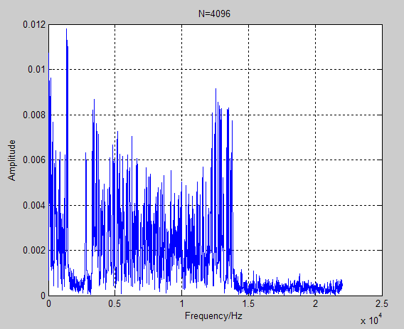
C4 Flute FFT
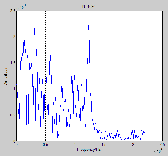
C4 Piano FFT
The graphs show that we need to add many sine waves together to generate a real-like sound. It is difficult to achieve on the microcontroller since those calculations will consume much of the CPU. To simplify it, we use three sine waves to generate the sine wave and the frequencies are f, f*3 and f*5. It simulate the sound well for the above program.
Sound output (DDS)
By using the DDS we can modulate the frequency of the wave. In the timer1 compare ISR, we change the value of OCR0A by a sineTable[]. We get the values in sineTable[] previously by sampling 256 points in a sine wave period. So each time the program goes into the ISR, OCR0A will change based on the sampling points. That means the output voltage value from PinB.3 will change in a sine wave form. This is the realization of DDS. For the frequency, the program goes into the ISR every 1/8000 s, so 2^16/8000*freq = 8.192*freq. From the above equation, we can convert frequency to DDS. Then the DDS is realized from the procedures described in the above paragraph.
LCD drawing
The LCD we use is a 2.8" TFT screen. It has a resolution of 320 × 240, as the following figure shows. There are 240 pixels each line and 320 pixels each column. We can use (x, y) coordinate to represent each pixel on screen.
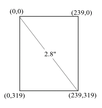
Resolution
Initialize of LCD screen
After a careful check of datasheet, we decide to use 8-bit interface. That is, the data bus is of width 8. There are some other control signals, including CS(chip selection), WR(write), RD( read), RST( reset), RS(register selection). The connection of these control and data signals to the AVR can be seen in the appendix. The ILI9325 has more than 40 16-bit control registers. To initialize the registers, it means we have to write the control bits to these registers. The following figure shows how we could write to these registers with 8-bit interface. According to the timing characteristic, we write several functions. They are:
void LCD_Write_bus( char VH, char VL) //write to bus
void LCD_Write_COM(char VH, char VL) //write command register
Void LCD_Write_DATA(char VH, char VL) // write data to register

Timing characterstic of 8-bit interface(from ILI 9325 dataheet in appendix)
Details of these functions are not included here. If you have interest, you could have a look at our code in appendix. Since our interface is 8-bit, it means that we have to send the data in high/low byte, so that it will send a 16-bit data. After writing the above three functions, it means that we could writing to these control registers. Details of the control bits written to each register are not shown here, they are also included in the code.
RGB565 interface
The ILI9325 chip has 172,800 bytes RAM for graphic data of 240RGBx320 dots. Here we use the 16 bit RGB interface, namely RGB565, that 5-bit for red, 6 bit for green, and 5-bit for blue. That is to say, we need to write 2 bytes(16 bits) data to each dot. In this way, we could use the funtion write above which also use a 16-bit data interface. A macro is written so that we can transfer the color we R,G,B value into RGB565, which is:
#define RGB565(r, g, b) ((r >> 3) << 11 | (g >> 2) << 5 | (b >> 3))
Drawing on LCD
After configuring the LCD, we write the function of drawing a pixel on the screen. This is doing to by the following procedure. There are two registers, 20/21 which represents the horizontal/vertical GRAM address set register. So our draw_pixel(unsigned int x, unsigned int y, unsigned int color) function, will first write the x and y value to the horizontal and vertical GRAM address set register. After doing this, we are telling the chip that we will write color to the dot (x, y) on screen. Then, after setting location, we will write the value of color to register 22, which is the GRAM data register. In this way, we can draw on pixel on the LCD with the color and location we want.
If we want to fill an rectangular area on the LCD, instead of using draw_pixel() function, we could use another way. By writing to register number 50 ~ 53, we can set the start/end position of horizontal/vertical address, that is, a rectangular area is now confined. The we can directly write values to register 22(GRAM data register), the chip will automatically increment the address vertically/horizontally, according to the control bits we set(that is, after filling a dot, the chip will automatically goto next dot, we only need to write another color value into register 22).
After having the pixel drawing and filling functions, we could extend them to other functions, a list of them a given below.
After having the pixel drawing and filling functions, we could extend them to other functions, a list of them a given below. After having these functions, it means that we could build our user interface based on them.
void Pant(char VH,char VL) // Pant the total screen to one color
void draw_line(unsigned int x1,unsigned int y1,unsigned int x2,unsigned int y2,unsigned int color)
void draw_circle(unsigned int x, unsigned int y, unsigned int r,unsigned int color)
void draw_rectangle(unsigned int x1, unsigned int y1,unsigned int x2,unsigned int y2, unsigned color)
LCD touch detecting
The Touch Panel is of the same size as the LCD Screen. It covers over the screen so that if we press a place on touch panel, we will know the (x, y) coordinate which corresponding to the screen.
The XPT2046 is a 4-wire resistive touch screen controller that incorporates a 12-bit 125 kHz sampling SAR typeA/D converter. The XPT2046 can detect the pressed screen location by performing two A/D conversions.
The following diagram shows the block diagram of the XPT2046. We will use the SPI interface provided by this module. We write two functions, WriteSPI() and ReadSPI() to communicate with the interface. The method we use to get the (x, y) coordinate is called differential reference. The theory is not explained here. If you have any interest, you can have a look at the datasheet of XPT2046 given in appendix.
There is a IRQ signal output, that only when we press the touch panel, the IRQ signal will become low. When released, it will become back to high. So we use INT0 external interrupt to detect the pressing. Every time the when detecting the falling edge of IRQ signal, we read the x, y data in the interrupt and decide the next step to do.
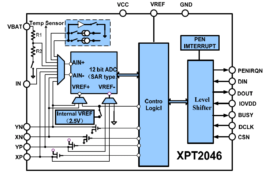
Function block diagram of touch panel (from XPT2046 datasheet in appendix)
Mainpage
The mainpage of our program will draw the user interface, which will tell users several modes to do. The modes include xylophone, flute, piano record, piano replay, free piano jam, and piano tutorial. We start drawing the mainpage by drawing several rectangles with different colors. We also shows the string of each mode in the rectangles. One figure of how our mainpage looks like is shown below. When we are in the mode of mainpage and we press the touch screen, we will go into one mode according to the y coordinate we get. For example, if we find that 40 < y < 80, we will transfer to flute mode.
When we are in other mode, if we would like to go back to mainpage, just click on the lower left part of the screen and we will go back to mainpage and draw the mainpage again.
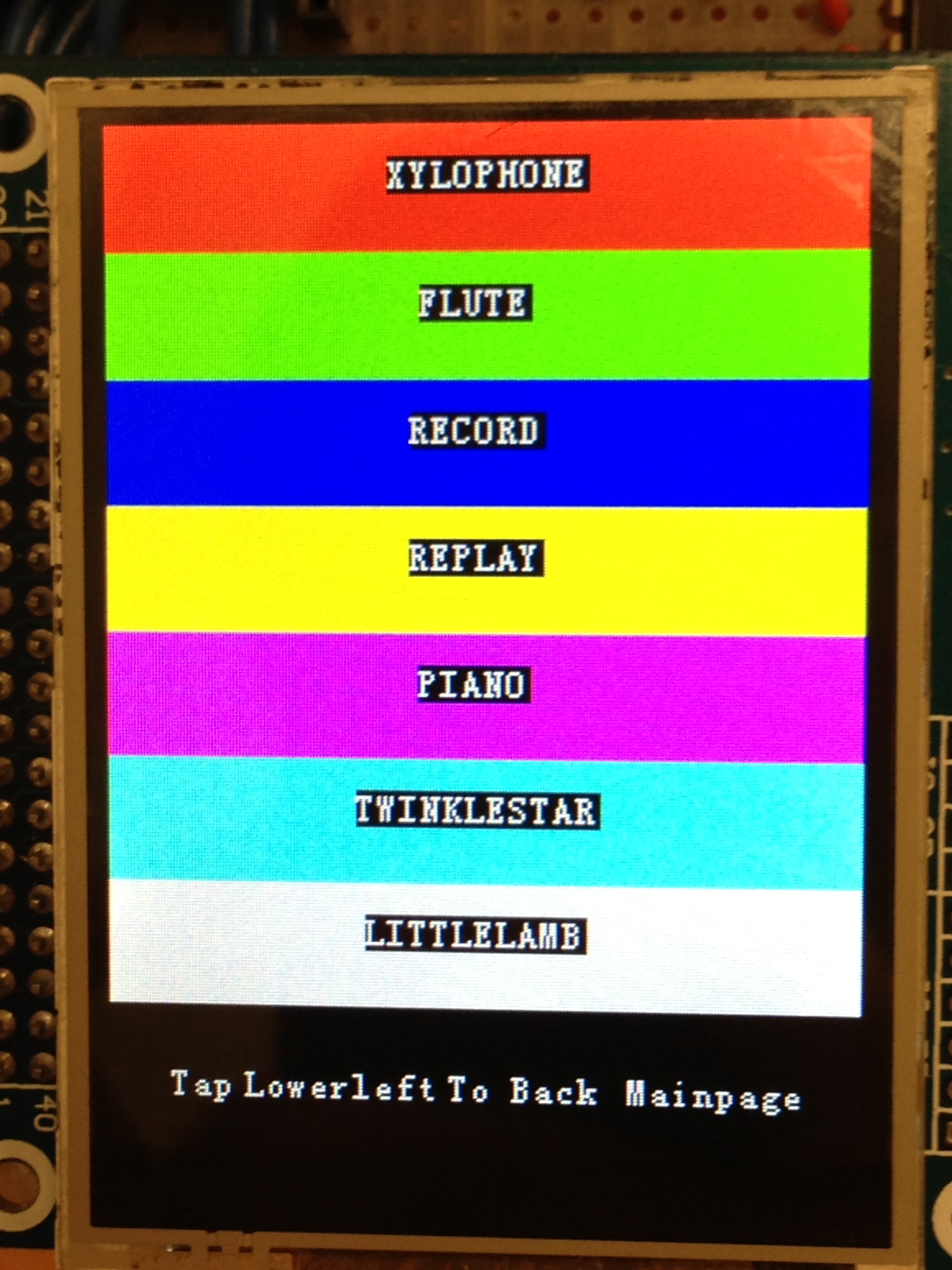
Mainpage
Xylophone mode
The xylophone is the first version of musical instrument we do. It simply consists of 8 color bar as shown in the below figure. Eight rectangles with different colors are drawn. Everytime when we touch the screen, in the ISR, we will get the (x, y) coordinate. According to (x, y) coordinate, we could know which color we are pressing. Each color corresponds to one note, from C5, D5, E5, ... to C6. To generate the waveform of each note, FM synthesis is used here.
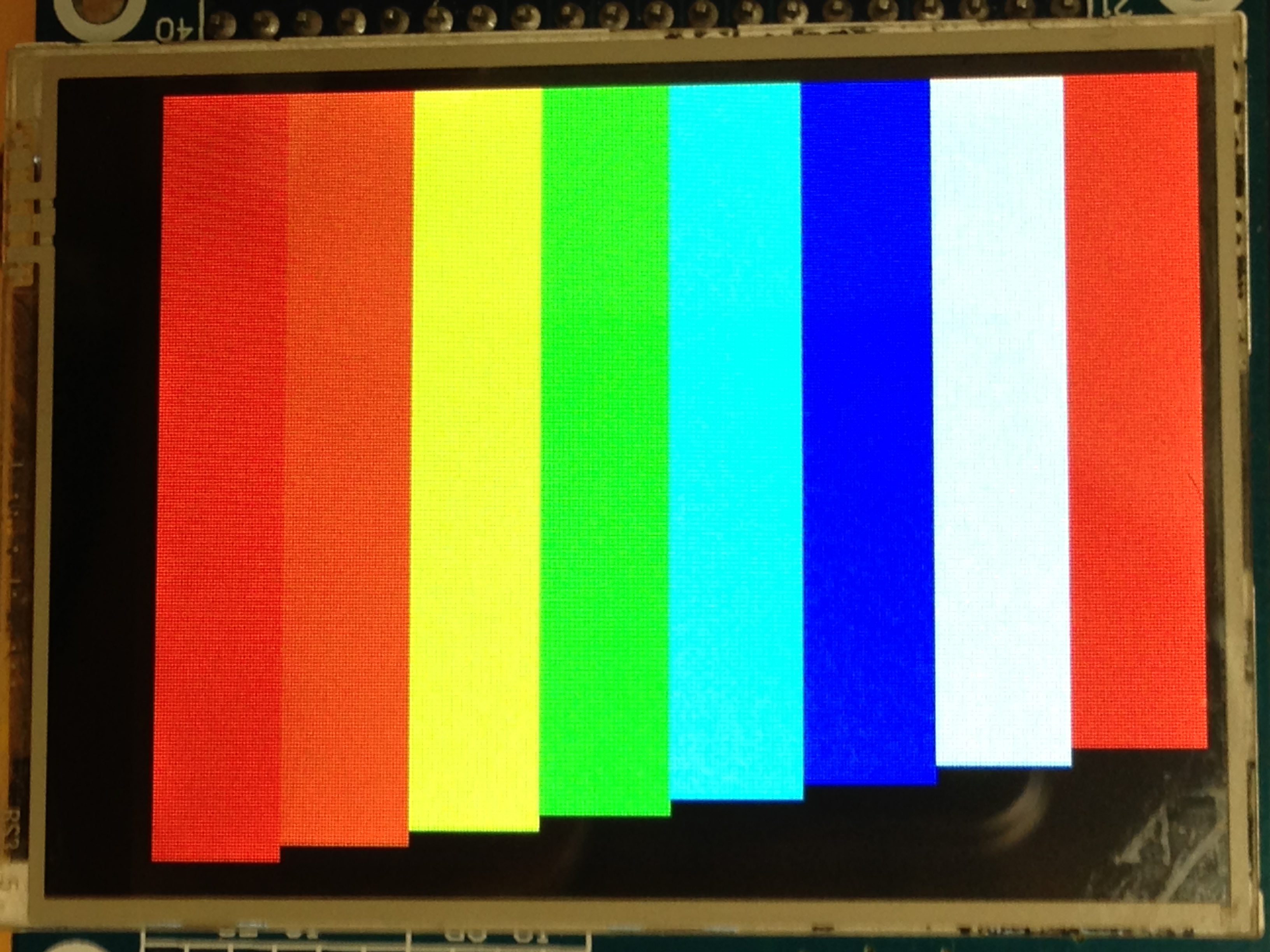
xylophone mode
Flute mode
The flute mode is the last musical instrument we implement. To draw the flute interface, the draw_rectangle and draw_circle functions are used. The below figure shows the how the flute is drawn. We first draw two black rectangles and on each rectangle we draw four white concentric circles. This will form 8 holes that we could draw on. A microphone is also used that when we are air blowing and at the same time covering one of the holes, a note will be generated.
We also add some visual effect when we covering the hole. That the outside circle will expand and shrink to show that the hole is covered. This is done by a timer counter, that when we cover the hole, we will reset the counter, clear the outside circle and draw a bigger circle. When the counter is bigger than a certain number, we will draw the outside circle back. This will cause a visual effect of expand and shrink.
Here, we use additive synthesis to generate flute notes.
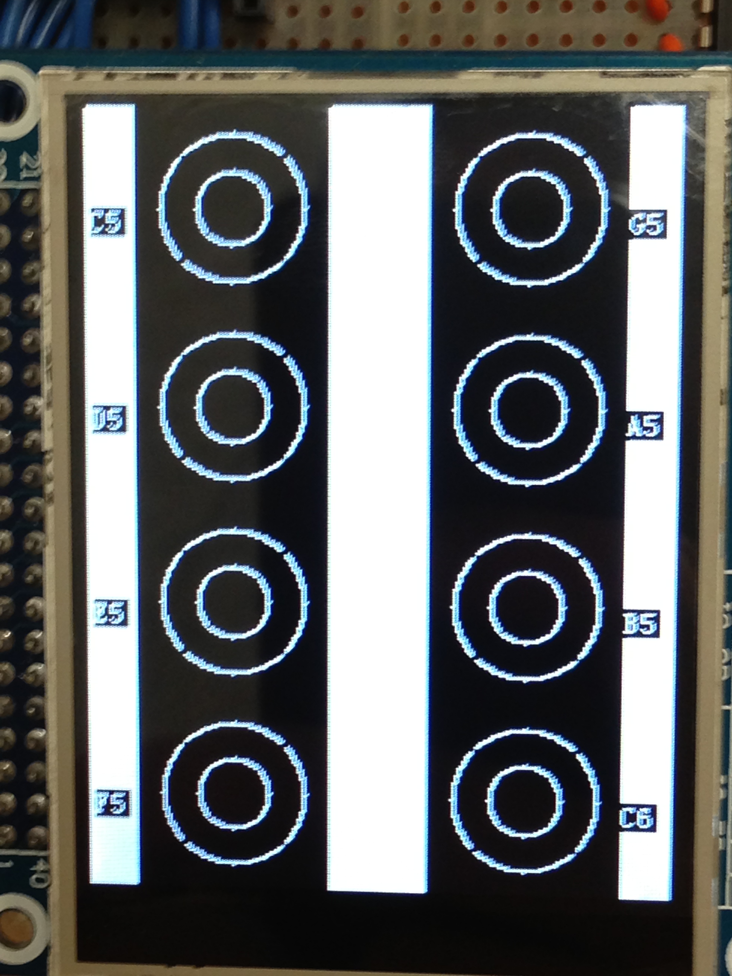
flute mode
Piano mode
To draw the piano on the screen, we first use Pant(0xff, 0xff) to pant the LCD white. Then we draw eight black lines to divide the black keys. We also draw five black rectangles to represent the black key. The following figure demonstrates the piano. In all the piano related mode, FM synthesis is used to generate the waveform we want.
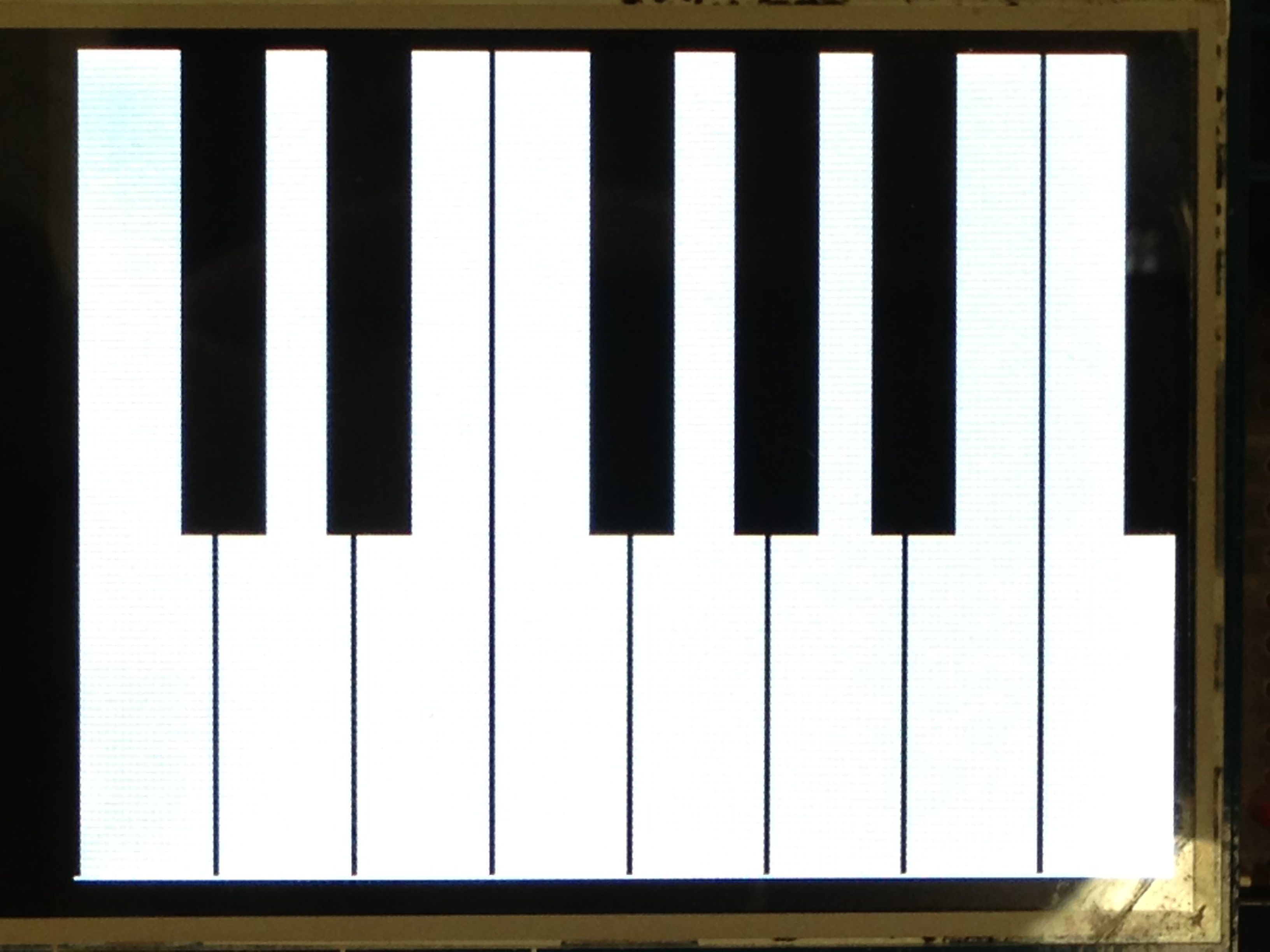
piano drawings
Free Piano Jam
The free piano mode, like its name indicates, user can play the piano free. To detect a note, every time when we press the touch panel, we detect the (x, y) coordinate in the INT0 external interrupt and thus determine which area (x, y) belongs to. There are total 5 black key and 8 white keys on the screen. That is to say, 13 notes can be generated. In the free piano mode, in the upper right , we can change the keys we want, from low, middle, to high. The figure below shows the three states. We use green to fill the area to show current key is low(C3 to C4), red to represents middle(C4 to C5) and blue to represents high(C5 to C6). A table of frequency talbe is also given for reference. The transition between low, middle, high is a simple state machine. When the state is low, if we press "-", nothing will happen, we will be still in low. But if we press "+", that to increase key, the color will transfer from green to red, which means we have change the key to middle.
We can leave the free piano mode by tapping the lower left of the screen and go back to main page.
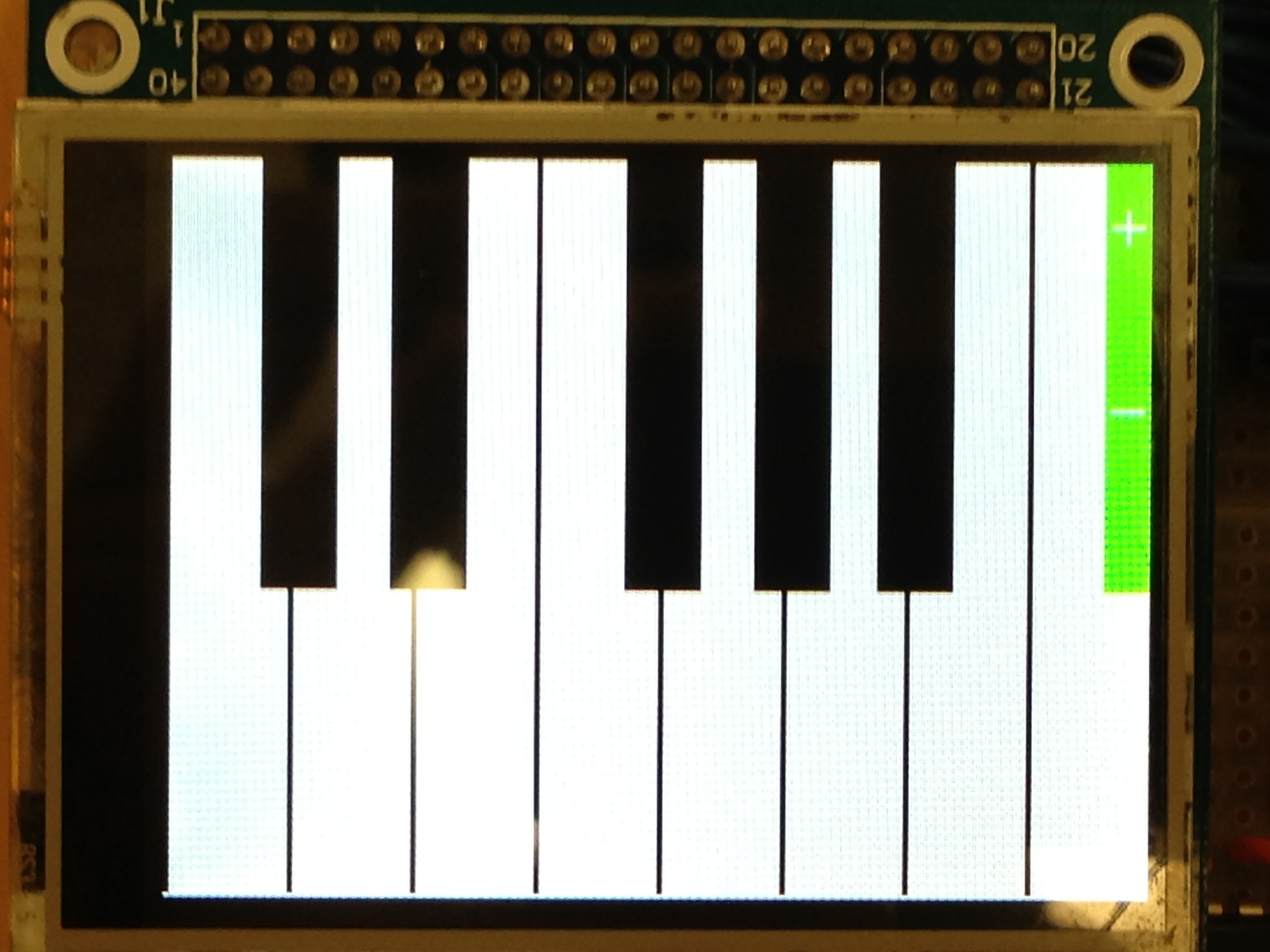
low key of piano, starting from C3
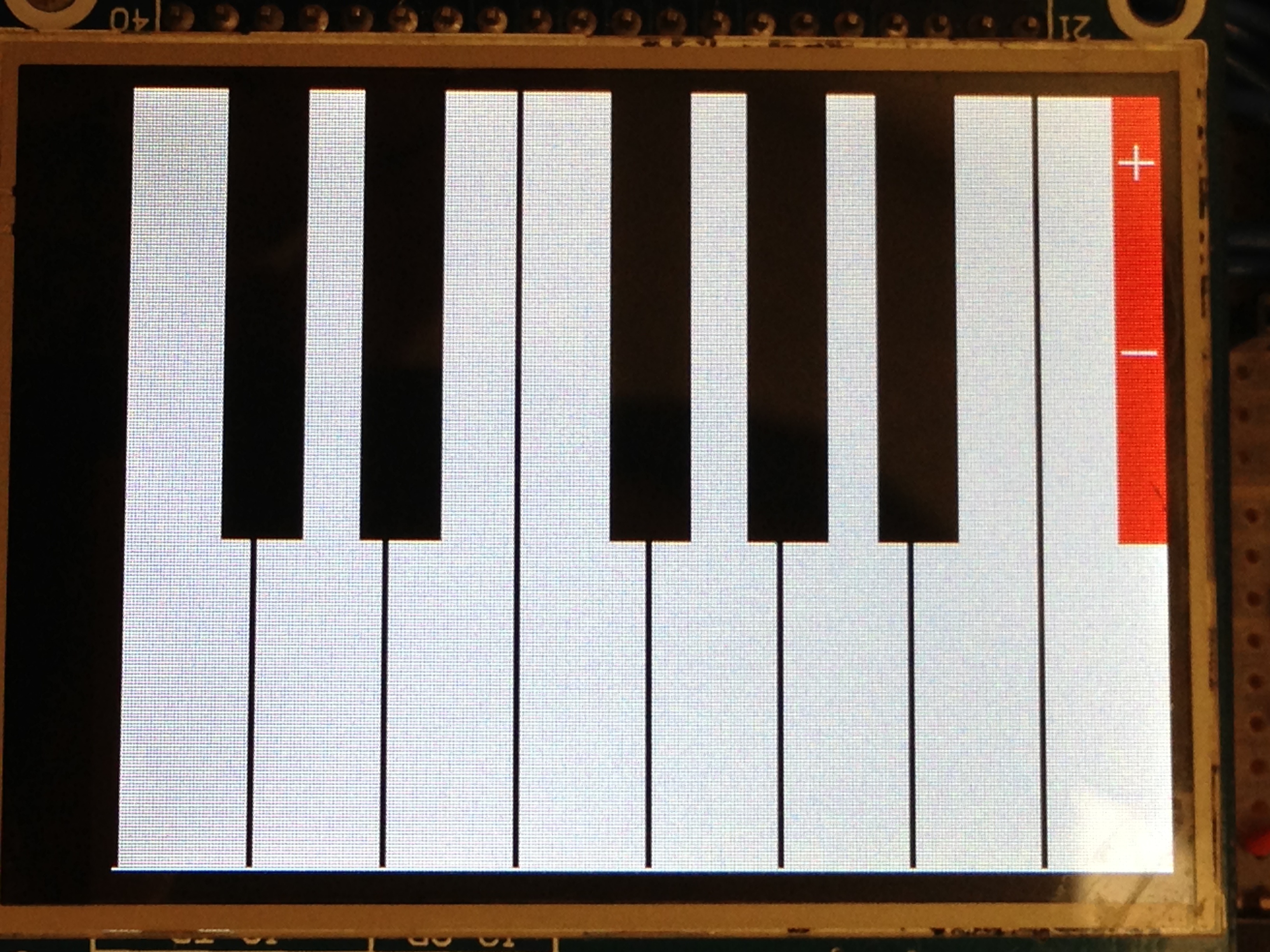
middle key of piano, starting from C4
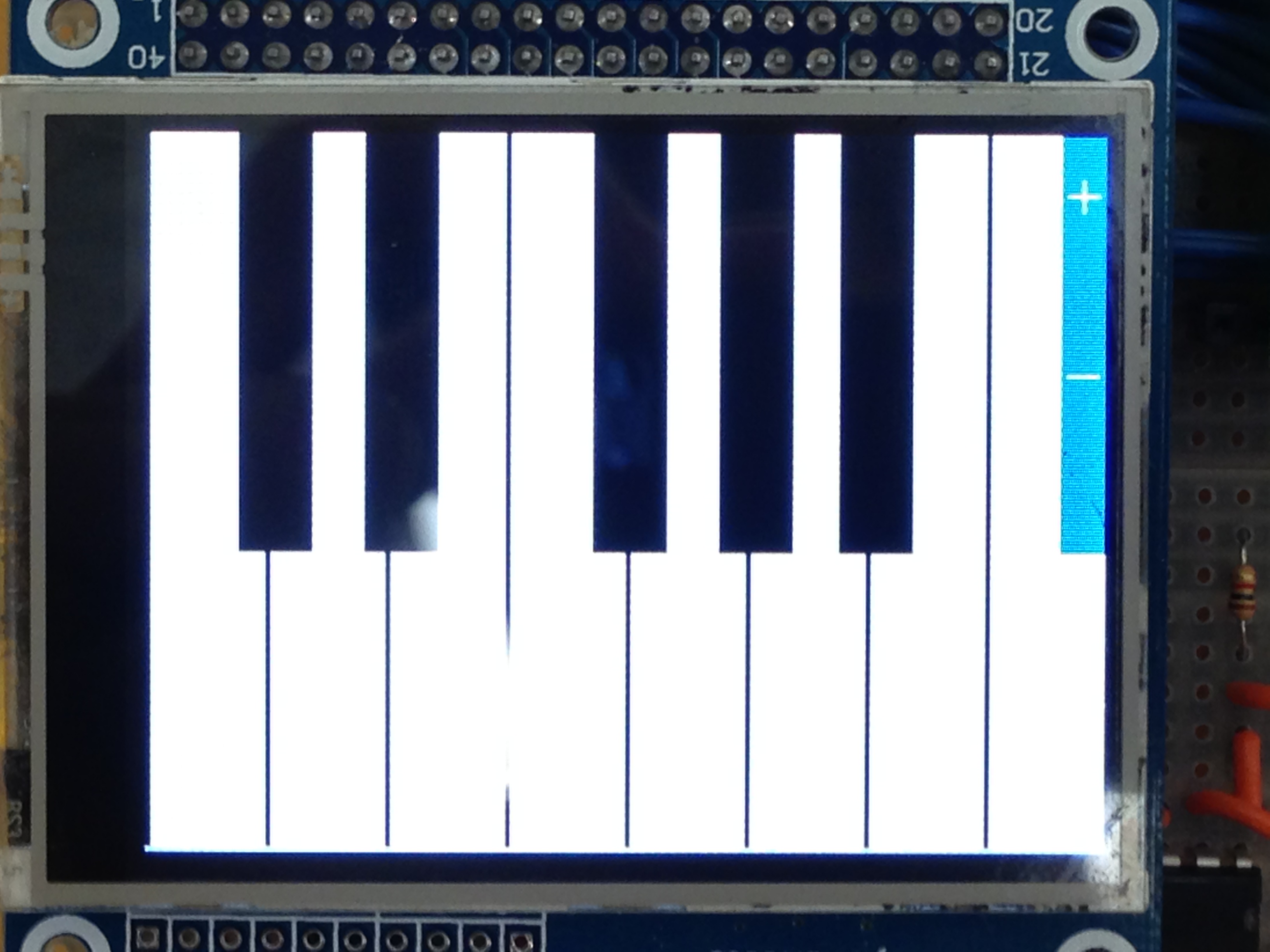
high key of piano, starting from C5
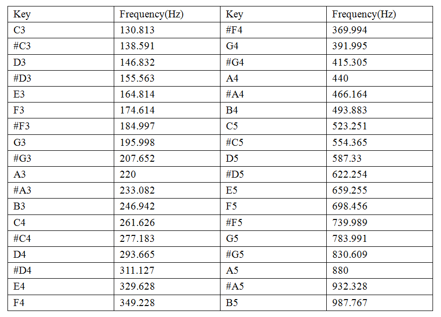
frequencytable on piano
Record/Replay
The record mode has the same interface of free piano, except that there is no transition between low, middle, high keys. The aim for record mode is that we could record a piece of consecutive notes with precise tempo. We use two 100 element arrays to save the key we pressed and the time interval between two consecutive notes. In this way, we can record precisely save these consecutive notes we pressed. To record the key we pressed, we have a mapping between the 13 keys on screen to number 1~13, while 0 in the array means no press. So every time we enter record node, we will reset all the elements in the note array to zero. To record the tempo, we have a counter, which is auto increment in the timer1_compare interrupt. Every time we detect a new note is pressed, we save the current counter number to tempo array and reset it to zero. When we detect a overflow( more than 100 notes), we will automatically go back to main page.
If we have recorded the notes we want, we could go back to mainpage by tapping the lower left part of screen.
The replay mode has the same interface of free piano, except that there is no transition between low, middle, high keys. The goal of replay mode is that we could automatically replay the music we recorded. We will display what keys we have pressed with precise tempo. The two arrays, note array and temp array will be used here. In replay mode, when we press the screen, no music will be generated.
To demonstrate the key we pressed, we write two functions, draw_key( ) and clear_key( ), which will fill the area of key into pink, or clear the pink color to white/black. Every time a counter counts to the value of current interval between notes, it will clear the old key and draw the current key. Then the program will wait until count to next interval. When we detect that the current note array element is 0 (no key pressed), it means that we have replayed to the final note, the program will automatically go back to main page. Certainly, we can also go back to main page manually by clicking the lower west part of the screen. The figure below demonstrates the piano key that is filled pink
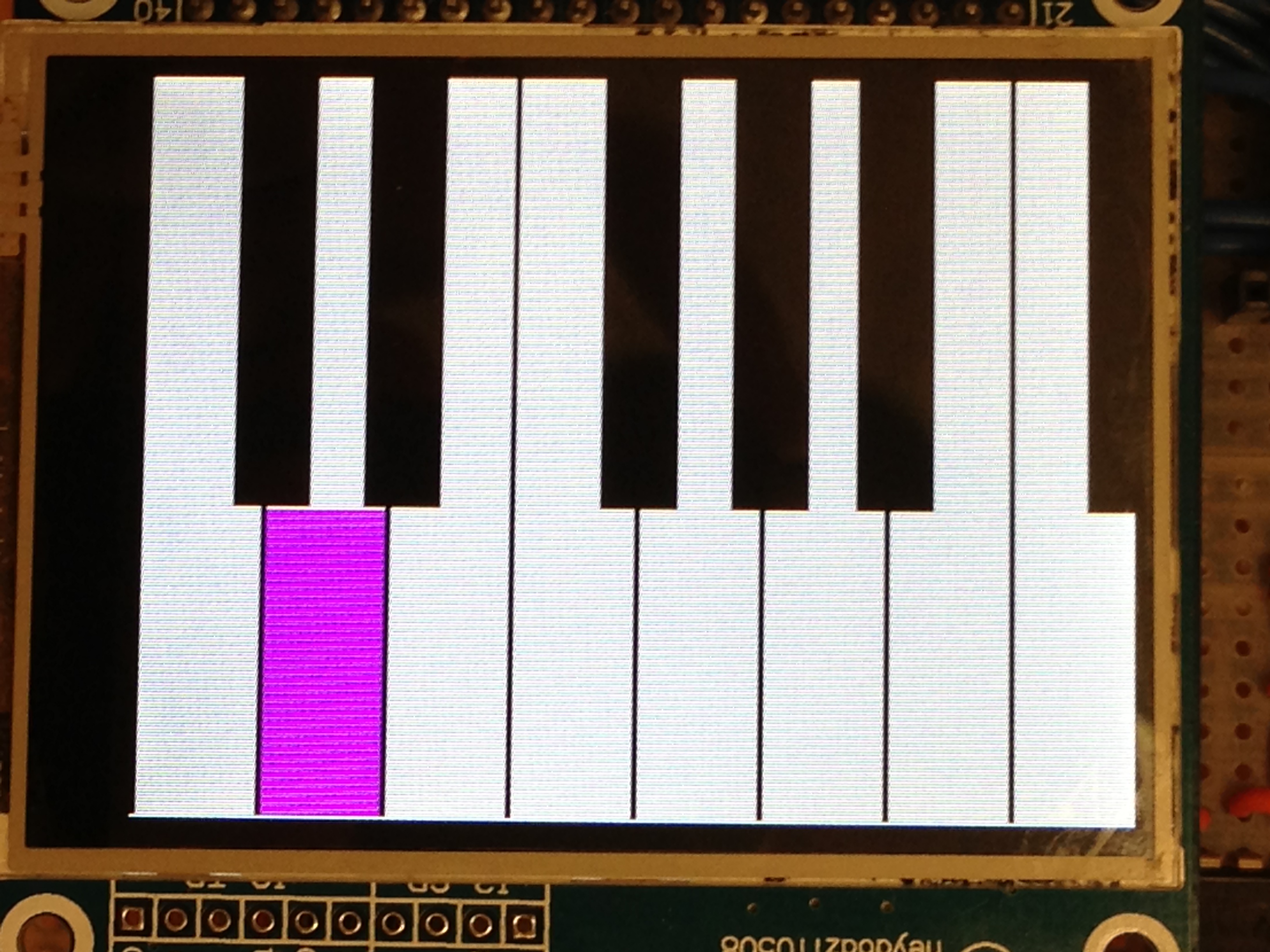
a key is filled in replay mode
Tutorial mode
In the tutorial mode, we have two songs, "Mary had a little lamb" and "Twinkle Star". The notes and tempo are previously saved in arrays. This mode is similar to replay mode except that the notes will not be automatically played. Users can follow the tutorial and play the right notes himself. If user press the WRONG key, the WRONG note will be generated.
There are also two ways to go back to main page, manually or automatically when the song is over.
Results
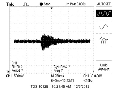
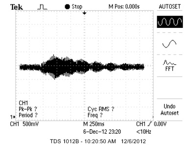
output waveform of piano and flute
Speed of Execution
Since our LCD screen has its own GRAM, as explained above, we do not need to spend time on refreshing the LCD. That is to say, more CPU resources can be used on other work. The speed of our note generation and press detection is real time. There is no delay in any cases. Most of the CPU is doing useful work. Actually we can add more real time stuff to our project because the CPU utilization is not so much high and we can support the real time work. All the mdoes function properly and there is a precise tempo for the record/replay mode.
Accuracy
The accuracy of our project is good. In our test cases, the identification of (x, y) coordinate is very precise. Accuracy is one of the most important part of our project, so we spend a lot of time on debugging this. The differential reference method is used in our identification. It turns out that though there will be some inaccuracy from time to time, but it's rare.
Another important case is about the accuracy of note generation. When in middle/low frequency(C3~C5), the note sounds well. But when the frequency is high(C5~C6), the note sounds not so good. There will be some inaccuracy because the modulate frequency is too high, that it is changing too fast, and it may sounds a bit weird.
But for addictive synthesis, in our flute design, since we synthesis the waveform directly from frequency range, the note sounds better at the same frequency, since the harmonic frequency we add are 3rd, and 5th.
Usability
This device is easy to use. We do not need anything else because we can press the screen by our fingers. It can be widely used in life, because our project is an app on a touch screen. Meanwhile, our system is also a prototype that more designs can be built on this. With the touch screen, microphone and earplug given, a lot of entertainment apps can be developed. This project also provides the library for future ECE4760 works on LCD touch screen initializing and development. In addition, this app can help children to learn the basic concepts of piano easily and know the white ot black keys on the piano. In brief, this app is of wide usability.
Safety
Our design is safe enough. By soldering all the components, we can avoid the potential for short circuit by carelessness. But the voltage on the transistor of Mega1284 board will achieve a voltage more than 12V, which is a little too high thus the current. We may need add some heat sink for that transitor. Apart from this, the other components are safe.
Conclusions
Achivements and improvements
Our design fully meets the requirements of our expectation: the free piano mode, the record/replay mode , the tutorial mode. In addition, we extend our design to other two instruments, the xylophone and the flute. So that there are more interactive between users and machines.
After working out this project, we find that there are a lot of things can be improved. To begin with, since the screen is a resistive touch screen, it can not support multi-point touch. So it is very difficult for us, or even impossible to detecting, for example, two pressing at different location at the same time. Maybe we can consider using a capacitive touch screen, but the cost will be higher. Another thing worth mentioning is that the accuray of touch panel is not such that high. We could improve this by adding more logic or lower the SPI speed. In current version of code we write, we add 5 nops between each bit transmission. If we add more nops, that is to lower the frequency to 1MHz, the accuracy may be higher. In addition, there are a lot more instruments that we can add, like drums, guitars, etc. But due to time constraints, we did not do so. We can also add more functions to this app. We have considered several possibilities, like scoring system, more visual effect, and so on.
Although there are so much imperfect, this project helps us to get a better understanding of modern LCDs and touch screens. We have a deep recognition of these devices and have made a library of LCDs for future ECE4760 work.
Standards
We have already mentioned the standards and patents we used. They are: <1>SPI <2>US3794748, Method of synthesizing a musical sound, by John M.Chowning in 1974
We conform to these standards and patents in our design.
Intellectual Property Considerations
In our code, two functions are borrowed from online resources. They are the draw_line and draw_circle functions. These two functions are common public AVR LCD functions. We also reuse Bruce's code for FM synthesis and additive synthesis. Our design uses others patent, but we have different approaches. We have never signed non-disclosure agreement.
Apart from the above, there is no other intellectual property issue.
Ethical Considerations
During our design process, our behaviours were consistent with the IEEE code of Ethics.
Our decisions are consistent with the health, and welfare of the public, and to disclose promptly factors that might endanger the public or the environment. We never think of or do anything that will be harmful to the environment and people.( IEEE code of Ethics, Code 1)
We are honest with our reference and code. We cite and mark all the part from other's help or online sources. We do most of the work ourself in labs and we are sure these work are not the same to other sources( IEEE code of Ethics, code 3)
Our design aims at providing children the platform to have a understanding of eletrical devices and the basic concepts of music. We also ( IEEE code of Ethics, code 5)
Out design is safe enough to avoid doing harm to any other people, their property, reputation, or employment. ( IEEE code of Ethics, code 9)
We do not receive bribery in all its forms( IEEE code of Ethics, code 4)
In doing this project, we treat fairly all persons regardless of such factors as race, religion, gender, disability, age, or national origin. ( IEEE code of Ethics, code 8)
Legal Considerations
Our design is carried out under legal power supply. What we have done is based on ensuring safety, stability and other's warefare.
Appendices
A. Code Listing
B. Schematics
Connection diagram of Mega1284 and LCD touch screen:
microphone input circuit:
Prototype Board PCB:
C. Parts List and Costs
| Part | Unit Cost | Vendor | Quantity | Total Cost |
| Custom PCB (designed by Bruce Land) | $4 | Lab Stock | 1 | $4 |
| Atmega 1284 | $5 | Lab Stock | 1 | $5 |
| small solder board | $1 | Lab Stock | 2 | $2 |
| Power Supply | $5 | Lab Stock | 1 | $5 |
| 40-pin DIP socket | $0.50 | Lab stock | 2 | $1 |
| Header pins/plugs | $0.05 | Lab stock | 76 | $3.8 |
| Speaker | $0 | Lab stock | 1 | $0 |
| Microphone | $0 | Lab stock | 1 | $0 |
| Resisots | $0 | Lab stock | 6 | $0 |
| Capacitor | $0 | Lab stock | 2 | $0 |
| LM386 | $0 | Lab Stock | 1 | $0 |
| LM358 | $0 | Lab stock | 1 | $0 |
| 3.5mm Audio jack | $0 | Lab Stock | 2 | $0 |
| Wire | $0 | Lab Stock | 30 | $0 |
| LCD touch screen | $0 | Previously owned | 1 | $0 |
| Total Cost | $20.8 |
D. Distribution of Work
Hao Sun
- High-level Design and Hardware Design
- Prototype board and microphone circuit soldering
- FM and Additive synthesis algorithm
- Report and Webpage
Kaiyu Shen
- High-level Design and Software Design
- Touch Screen Control
- Modes realization and Instrument Interface
- Report and Webpage
References
Below are links to external documents, code, and websites referenced and used throughout the duration of this project.


