
"Feel virtual objects with haptic feedback in full 3D by manipulating a stylus that tracks user movements with respect to floating truss system."
project feel-weird-objects
The goal of our project was to create both the hardware and software platform that can be used as a adaptable haptic data visualization device. Imagine you have a complex data set from which you create a surface plot in MATLAB. Sure, it's nice to see the data on the computer screen, but what if you could feel it? Bring it to life? With our current haptic visualizer, users can feel any arbitrary surface plot generated in MATLAB as well as animate and manipulate a 3D sandbox used to draw and feel objects. At the current stage of our project, both programs are fully functional with plans of eventually supporting the import of SolidWorks files. Once the user initializes a sandbox or loads a data set, a human-sized suspended triangular truss system tracks the real-time movement of a stylus and animates a pointer on screen. As the user penetrates an object or surface, vibration motors embedded on the pen give the user a sense of depth and material stiffness.
The world of haptics is growing with many new applications emerging every year; however, most applications are within the consumer electronics domain as vibration feedback on phones and gadgets. We saw the potential and value of having a flexible visualization platform with which the science, business, and art worlds can use to aid to help bring their work to life. This project came as a natural extension of our previous experiences in both hardware and software and proved to be a reward experience synthesizing all of our previous knowledge.
High Level Design
Logical Structure
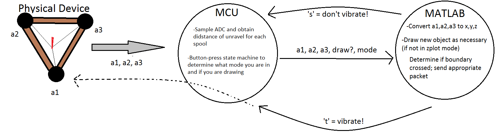
Logical flow diagram for the Haptic Data Visualizer
The above state diagram shows the flow of the system and how the corresponding components interact. The physical truss apparatus tracks the position in space of the pen stylus with the voltages on the three potentiometers at each vertex. Each potetiometer is read sequentially by the microcontroller is packaged and sent through serial communicaiton to MATLAB. MATLAB then parses the incoming string and extracts the respective ADC values. These ADC values are transformed into Cartesian coordinates by the trilateration method described in the Software Section. MATLAB controls all of the animation and plotting. Currently, there are two modes of the software. The first, called Surface Mode, allows users to load in a surface plot (from peaks(n) for example) and "feel" the plot when penetrated from the z-direction. In this mode MATLAB creates a surface plot and animates a cursor on the screen that corresponds to the position of the pen in 3-space. Any position below the displayed surface will cause the stylus vibrate proportional to amount below. In Object Mode, the user has the ability to place objects (currently limited to cylinders, spheres, and cubes) arbitrarily in the 3D canvas. Again, when the user positions the stylus inside of an object, the HMI vibrates. In both modes the MATLAB software does the majority of the data processing and the microcontroller is limited to ADC polling, controlling the vibration motor, and communication. Once MATLAB determines the cursor is at a boundary, it sends a return byte to the microcontroller that dictates the state of the vibration motor. Refer to the above diagram for a system level view of how the Haptic Data Visualizer works.
Hardware/Software Tradeoffs
In this project, we decided to have the microcontroller communicate to MATLAB for two main reasons. The processing power of MATLAB, running on a computer, is orders of magnitude greater than any microprocessor and is better suited for data processing. We knew that the microcontroller was going to be the bottlekneck in this processor, and if we could unload processes from it, it would greatly benefit our device. This was a logical decision and was made early on in our project which dictacted how we proceded for the rest of the project. Fortunately, for our project, there were not many tradeoffs that we had to balance between hardware and software and the division of tasks was clear.
Existing Products and Intellectual Property
Haptics – the study and science of touch and feedback – is an enormously broad area of study for many universities and independent researchers across the world. It is used to simulate everything from video game textures to robotic skin to precise surgical tools. As a result, there are several devices on the market already that incorporate pieces of what we hope to achieve with our own project. Each is different from the next, but they all converge on some of the basic principles of haptic feedback.
One major example is Novint’s Novint Falcon, a pistol-shaped controller for augmenting video game experiences. It uses a ball attached to a large collection of motors and arms to apply pressure in certain configurations to simulate videogame textures. It was launched in 2008 to universal praise for its realism and ingenuity. There are a few catches – first is the $280 price tag, and second is that it is quite heavy and makes no consideration for people who cannot hold a thirty-pound controller for long stretches of time; nor is it easy to use for left-handed people, as the device was designed with right-handed users in mind.
Another similar project was done at the University of North Carolina in 2001, called DAB: Interactive Haptic Painting with 3D Virtual Brushes. The purpose of this project was to create a virtual interface for painting pictures, with brushstroke feedback so as to create a more realistic sensation of painting – on a monitor. This project is different than ours in a few ways. First of all, it provides feedback only for the brushstroke sand palettes – we, on the other hand, will be providing a sense of boundaries when tracing the contours of a virtual three-dimensional object. Secondly, although the implementation of the mechanical feedback arm looks similar to what we had envisioned, it is programmed and designed for artists, whereas our device is targeted towards gamers and people who want to feel imaginary objects.
Hardware
Microcontroller
For this project, we used the Atmel ATmega1284 microcontroller mounted on a custom printed circuit board designed by Bruce Land for the purpose of this class.
Full circuit schematic can be found in Appendix B.
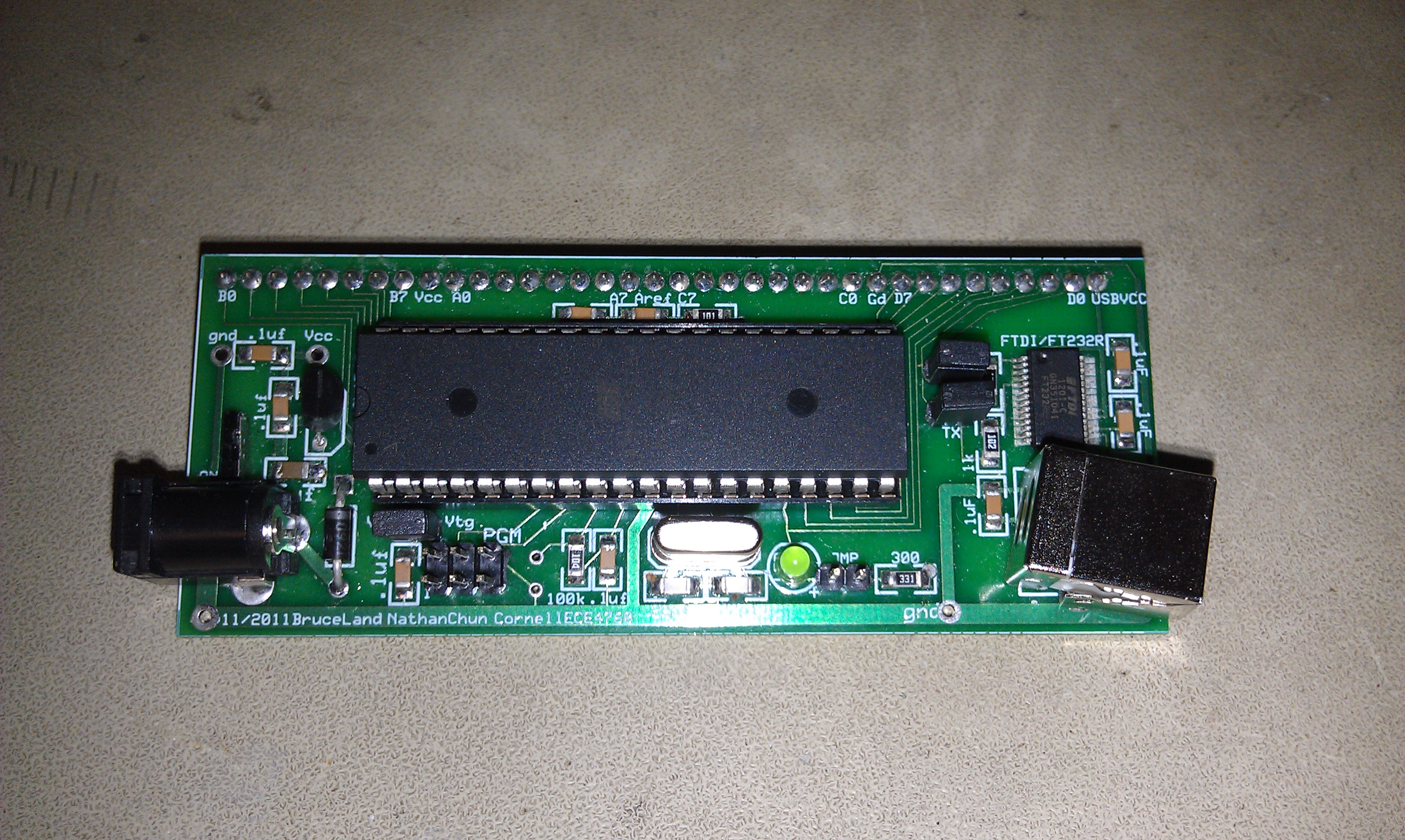
ATmega1284 microcontroller
Truss Mount
Our final hardware iteration is the following setup:
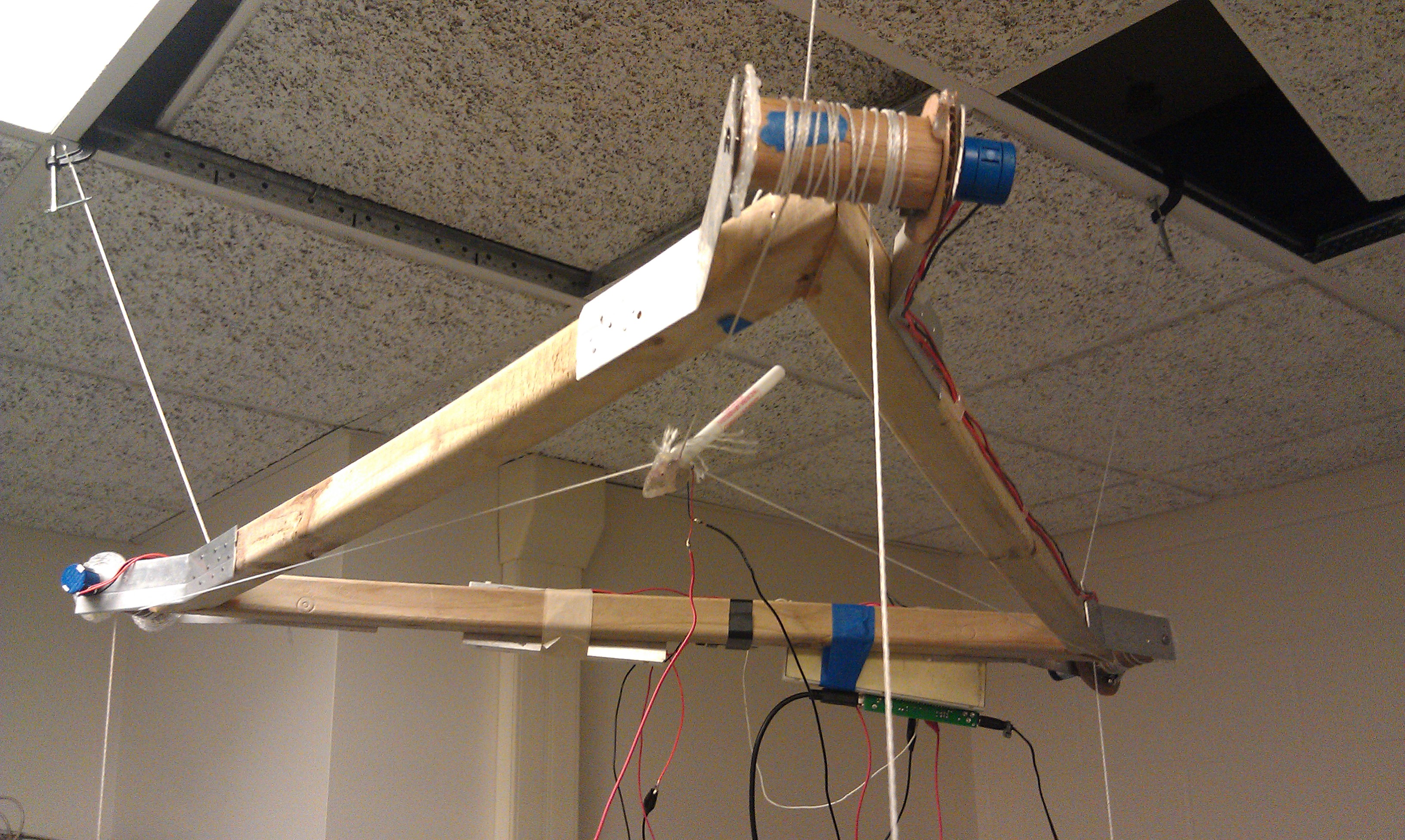
Final product.
The triangular truss system consists of three equal lengths of 1.5"x1.5" pressure treated lumbar that comprise the sides. A table saw was used to make the 30° miter cuts at the vertices to create the proper geometry. Attached to each vertex, are two metal shims that hold a wooden spool to which a 10 turn potentiometer is attached.
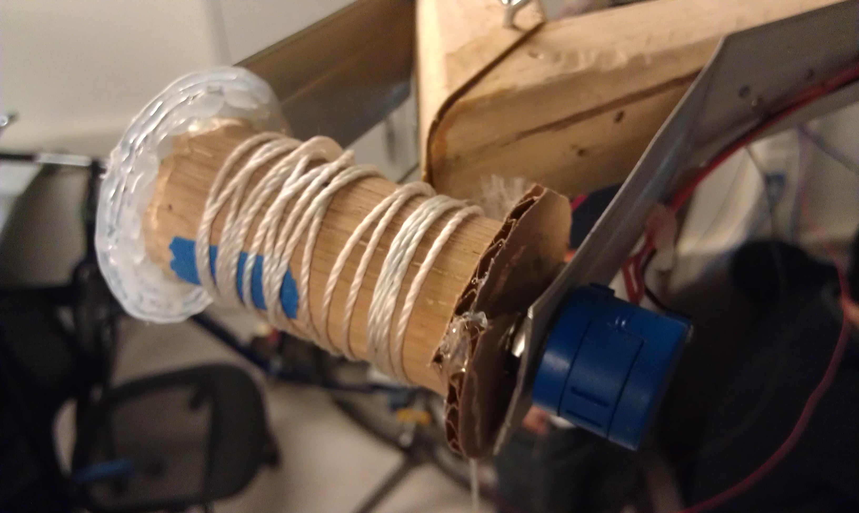
Close up of a spool.
On each spool, there are two strings wound in opposing directions. To one, there is a counterweight that provides a constant torque that winds in the spool and keeps the string taught. To the other line, all strings are attached via hot glue to a stylus (a common plastic ball point pen) which becomes the HMI (seen below). There is a vibration motor hot glued to the pen that provides the haptic feedback.

Pen with vibration motor.
Full source code can be found in Appendix A.
Microcontroller Software
PWM
To regulate the vibration motor on the stylus, we used pulse width modulation (PWM). Initially, we had 3 motors on each corner of the triangular frame to keep each spool taut. This required us having to do 4 PWMs, 3 on timer0 and 1 on timer2, each with a connection opto-isolator circuit. We were going to have PWM each motor to a low value which would supply a low voltage that would create a low torque used to reel in the excess string and keep lines taut. However, we were unable to find a suitable motor that was powerful enough to produce a sufficiently large torque for force feedback that had low enough internal friction that could be easily backdrivable. Instead, we moved to a passive weight torque system that uses a counterweight that provides the torque needed to keep strings wound an taut.
The motor control signal as calculated by the controller is outputted via pulse width modulation (PWM) on PORTB.3, enabled in the intialization method. PWM is, essentially, a way of converting an disrete digital output signal into an analog signal. During each PWM cycle (256 clock cycles), the output port can vary (in "fast" mode) the fraction of the 256 cycle it is high, known as it duty cycle. Integrated over each PWM cycle, the descrete digital wave becomes an analog signal, proportional to the number of cycles spent high. This can be expressed as the following equation:

Where n is the number of cycles during each PWM cycle that the output is high. A visual to help understand PWM is provided below:
Visual representation of a PWM signal.
(source: http://www.societyofrobots.com/schematics_h-bridgedes.shtml)
The PWM output is then passed through the following circuit to electrically isolate the microcontroller from the motor powering circuit. This is essential because the motor acts as a huge inductor and at the end of each duty cycle when the "switch" is turned off, there is a sizeable back electromagnetic field (EMF) across the motor terminals which produces a significant amount of noise, enough to force continual microcontroller resests. The capacitor across the motor filters out the high frequency noise and the diode provides a path to ground out the induced current when the electronic gate is opened.
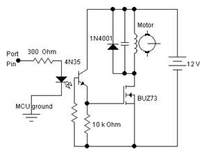
Optoisolator and motor power circuit.
(taken from: http://people.ece.cornell.edu/land/courses/ece4760/labs/f2012/lab4.html)
The schematics for the 4N35 and BUZ73 integrated circuits are shown below and will aid in proper circuit assembly.

Integrated circuit schematics.
(taken from: http://people.ece.cornell.edu/land/courses/ece4760/labs/f2012/lab4.html)
This optoisolator circuit is the actual unit that decouples the microcontroller and motor ground and prevents any noise crosstalk and works by internal emitter and phototransitor communication.
Push Buttons and User Interface
We debounced 2 push buttons that were used to interact with the entire functional system. Both buttons were connected via a 30-ohm resistor to ports D.5 and D.6. The first button was used to indicate a switch between 2 modes: 1. drawing cubes 2. drawing spheres. The second button was used to indicate to draw the object in virtual space in MATLAB. The object drawn is dependent on the current mode (cube or sphere). The following state machine diagram highlights debouncing the buttons to check for a valid press:
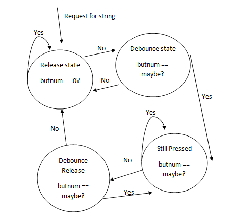
State machine diagram for debouncing button presses.
In main, stateMachine() is called every 30ms (tracked by a counter in the 1ms timer 1 interrupt). A valid press is one which is held for 2 cycles of 30ms (60ms) while the converse is true for a valid release.
USART
To send data packets to and from the MCU and MATLAB, we used serial port communication. To establish communication, we made MATLAB send a dummy packet each time, before each message was sent from the MCU. The dummy packet indicated whether connection was established and whether or not the stylus was within the boundaries of the virtual MATLAB Object. On the MCU, we sent each message in the following encoded format:
printf("%dx %dy %dz %dd %dm\r",adcVal,adcVal1,adcVal2,drawPress,choosePress);
Each message from the MCU had information regarding the 3 spool length in triangular 3D coordinate system and user messages indicated via the 2 buttons (to draw a shape and the chosen shape draw mode). To increase speed of boundary detection especially when the stylus is moved quickly, we increased the baud rate to by setting the UBBR0L register accordingly to 8, corresponding to a baud rate of 115200. Further details are given in the MATLAB section.
ADC Sampling
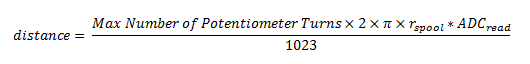
To extrapolate 3D coordinates in the triangular-based spool system, we made use of three 10-turn potentiometers, each with a spool of thread wound on it. Each potentiometer reading was ADC sampled and internally scaled to a 10 bit value (0 to 1023). Since we were using 10-bit precision, we had to read the low byte (ADCL) before reading the high byte (ADCH) register during each ADC Read. The timer1 clear on match interrupt triggered every millisecond, is used to do an ADC Read on the previous sampled value and to start a new ADC sample conversion. Since, we needed to ADC Sample across 3 ports (ports A.0, A.1 and A.2) and could only use a single ADC channel at any time, we cycled periodically through each to give all three spool distances in 3D triangular space. To convert the 10-bit ADC value to the length of thread unrolled we used the following conversion formula:
MATLAB Software
There are two software packages that were written to form an adaptable and agile development platform for futher advacement: one, called Surfaces.m, is designed to allow the user to feel complex curved surfaces, with a fixed base on the z-plane. The other, called Objects.m, allows users to place spheres and cubes in three-space, then trace them with a stylus. In both packages, the haptic feedback is given by a vibrating motor at the base of the stylus. The primary function of MATLAB here is twofold; first and foremost, to use its extensive collection of graphics libraries to give a strong visual element to our design; second, to handle many of the more complicated calculations (such as boundary detection and vector arithmetic) that would have proved too computationally intensive to perform on the controller. To convert from the awkward coordinate system given by ADC values of respective radii of the spools, we used a technique called trilateration (used in tracking location). If you have information about the distance of a point from three other points, then you can take the point to be intersection of three spheres centered at those three other points. In our system, the three other points and the three corners of our triangular base. The three spheres can intersect twice once above once below. But we know that movement is always below the triangular base. All the serial communication libraries and graphics libraries were built off of Bruce Land’s supplied code, listed in the References Section.
Overall View - Surfaces.m

User interface in Surface mode.
In Surfaces.m, we take advantage of the face that MATLAB allows surface plots known as "zplots" to be stored as two-dimensional arrays. These arrays are essentially x-by-y coordinates (corresponding to indices), the value of which is the z-coordinate in the plane. This format lends itself to extremely efficient x-y-z lookup. From a top-down perspective, we are simply creating an interesting surface shape, storing it as a zplot, and then taking the x-y-z coordinates of the mechanical frame and doing a trivial lookup to see if a boundary has been crossed. If it has, send a packet to the controller telling it to activate PWM and vibrate the motor. If not, then do nothing. No matter what, keep looking and updating the x-y-z coordinate, until the program exits. The user’s cursor is represented by a small circle, but this is unfortunately an unrealistic representation, as it is in 2D – but it is the only type allowed by the zplot.
Overall View - Objects.m

User interface in Objects mode.
The goal of this program was to be able to not only feel pre-existing objects but to create new ones altogether. This program is slightly more complicated because it requires a different kind of x-y-z lookup logic. These objects are created with the CSG Object library, and are stored in a much different way than a zplot. Instead, every CSG object has within itself a 3-by-x matrix (where x is dependent on the resolution of the object) that contains all the surface points of the object in a -1 to 1 scale in all three dimensions. To update the cursor, we needed animation – so we created a function whose job it is to continuously clear the entire plane, and then redraw the static elements in the same spot and the cursor element in the original spot plus the change in x-y-z. Thus, the illusion of an animated, updated cursor is created. By moving this cursor representation around the screen in real time, we give the user a better sense of location in three-space. These x-y-z points are taken and compared with the objects in two ways: for the cubes, we simply check if the point is within all size faces, which only requires knowledge of the min’s and max’s of each dimension on the surface matrix. For the spheres, we take the distance of the x-y-z coordinate from the origin of the sphere, and compare it to the radius.
The "mins/maxs" and "radii" are actually arrays, and every additional object is an additional array entry: animation function is called one per pass through the main loop, and for every animation call, all the boundaries (the entire array) are checked. MATLAB is able to do this iterative calculation quickly enough compared to the bottleneck (the actual rendering) that it does not affect performance. The drawing is done by pressing a button on the stylus, and a second button determines whether the user is in "Cube Mode" or "Sphere Mode."
Graphics Libraries
The graphics used in these programs were built off of libraries taken from Bruce Land titled "Constructive Solid Geometry," it is based on the principle that complex three-dimensional shapes can be formed by combining the 3D fields of elementary shapes stored as “positive outside, negative inside.” There are many library functions that take advantage of the ease with which these models can be combined; basic, overlapping CSGcubes can, for instance, be subtracted from each other with CSGsubtract(cube1, cube2). The only parameters needed to build the basic CSGcube, CSGcylinder, and CSGsphere are the x-y-z center points, the size (or radius), the resolution (which is maxed out at res = 50), and, in the special case of the cylinder, the height’s axis.
When a CSG object is created, it is saved as the aforementioned "negative inside, positive outside" matrix. For rudimentary objects, this is a very simple representation, where a cube of resolution 3 may for instance appear as:
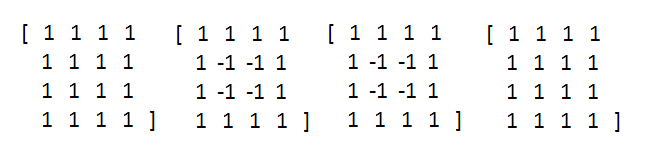
Combining objects obscures this simple representation, and creates non-1 values. Therefore, another way to look at objects had to be used. As it turns out, when a CSG object is passed through CSGtoSurface (which is necessary to render it to the screen), the resulting object is stored as a structure containing, among other things, a matrix of surface points. By checking against this matrix, we were able to determine boundaries corresponding to real-world positioning. Finally, this CSGtoSurface is passed to renderpatch(object) and drawn to the screen. We used a simple stationary face lighting in order to show the dimensions (not including lighting would make the image appear one-dimensional), and we turned on 3D-rotating of the plot.
Serial Communication:
Connection between the ATmega and MATLAB has already been discussed from the controller side; here, we will briefly mention the nuances of serial connection from the MATLAB end. One of the first commands we call is fclose(instrfind); this is similar to other close commands such as close all and clear all, but it specifically eliminates any unwanted, bogus serial connections. The actual setup of a new serial connection is a two-step process: first, the communications variable (called s in our codes) is defined by serial(communications channel, baudrate, terminator character). Baud rate determines how fast packets are sent over the channel. For higher performance – at the cost of accuracy – we chose a baudrate of 115200. According to the chart of baud rates, this introduces an error of 8.5%. This was deemed an appropriate tradeoff in terms of bit accuracy, and may have contributed (among the inherent inaccuracy of running ADC at full-speed, ten-bit mode) to the ever slight tremor of the cursor at rest – more on this later. The terminator character, for us, was chosen to be the "/r" seen in the C serial code.

Taken from Page 200 of the ATmega1284 datasheet
With the serial package defined as s, the next step is to establish connection with fopen(s). This command hijacks the communications port specifiedss earlier. Since this microcontroller only has one such port (through USART), it was impossible to debug with UART once the connection was made. This was not an issue, since we could simply print our visual debugging statements through MATLAB instead.
"Are you ready?" "Yes, I’m ready." "Are you sure?" "Yes, just do it already!"
MATLAB is extremely finicky about its serial communications protocol. In establishing connections and engaging in reliable data transfers across networks, it is common to use what has been coined a "handshake" between the involved parties to assure a packet is getting through. MATLAB demands the first move; it will not allow reliable packet reading on its own end until it is sure a channel has been opened, and the only way to be sure of that is for it to be the first to send and solicit a garbage response before getting to business (ie: the "handshake"). Communications are sent from MATLAB using fprintf, so no matter the functionality, MATLAB codes written for this project send a garbage 's' character first (which corresponds to "I'm here! And don't vibrate yet!") and receive some preliminary garbage in return (which is why an fscanf is done, then the stored data is immediately overwritten). Now, MATLAB is ready for real communications!
Everything is a state machine, after all
Because the size of a packet is very limited, we decided to design our system such that there were two separate, minimalist packets which MATLAB could send the microcontroller to let it know whether our cursor was within a boundary or not. If MATLAB sends the controller an 's', it knows to keep sending coordinates but it will not PWM the motor; likewise, if MATLAB recognizes that we are within a boundary, it sends a 't', from which the controller knows to activate the PWM. The reading-writing-reading dynamic must be held constant until the program is terminated, so it is contained as the first instruction within a while(1) loop.
The next thing that happens is also the same no matter which file you are exploring: the incoming packet, read from fscanf, contains certain valuable data that must be converted from a string to a number in order to be useable. The general format we followed was to send packets from the microcontroller as a single, large string that contained everything we needed separated by certain markers. For instance, we could send "13x212y251z," and this would then be converted into an x, y, and z integer coordinate by taking the strfind of those special character markers and using them as indices of substrings. This is a very general example; for our code, we also used other special markers for items such as "sphere mode vs cube mode" and "are you drawing now?"
Iterate, iterate, and…… iterate!
Like the hardware and C code, our MATLAB implementation saw a number of updates and revisions throughout its design cycle. For one thing, the idea to draw to the screen in real-time wasn’t even something we were committed to doing until we realized that some students had done it (using the same libraries, but for a different purpose and having a different implementation) for a previous final project (see Haptic Glove). Our original idea was to create objects in SolidWorks, then somehow port those objects to the microcontroller. We later discovered that SolidWorks objects can be transferred to MATLAB, where they are presumably stored in a matrix form that could be susceptible to some form of boundary checking. This was perhaps one of our more ambitious ideas, and it ultimately did not come to fruition due only to a shortage of time needed to work on integrating those libraries.
We decided a happy middle ground was to simple design objects in MATLAB and render them directly from that code. Even then, our design saw many different versions. Our current packet sending-receiving system is the product of massive amounts of iteration. Because we lacked access to UART during the testing phase, we relied solely on MATLAB output to know whether we were on the right track or not (before our graphics were working). For instance, our very first triumph was being able to turn a packet string of x-y-z coordinates from the microcontroller into x-y-z integers in MATLAB, and printing them to the screen while being manipulated by a single spool in the z-direction. Once we had this working, we knew the rest of the project was doable.
At one time, there was only a single "draw" button, and the packet looked like "_x_y_z_draw." The only object available to draw was a cube, but because of the simplicity of this packet, holding down the single button allowed continuous drawing. When we changed the packet to "_x_y_z_d_m," we had changed the core functionality of the drawing function by turning the C code portion of the button press into a two-button-optimized state machine that sent a "pulse" rather than allowing holding the button for a prolonged period of time. Now, you could no longer hold and draw, but rather "place" objects to the screen. The functionality had changed from "drawing 3D objects" to "placing 3D objects on the canvas."
Finally, feeling surfaces was something we added much later than the 3D shapes program. It was something we knew we wanted to do from the beginning, and we always had an idea of how it might be possible in theory, but we didn't actually commit to implementing it until we were sure we had mastered the 3D shapes program.
Results
Speed of Execution and Accuracy
We chose to run our ADC's at full speed, and with full ten bits (from 0 to 1023). This allowed the best precision and speed the microcontroller would allow, but it hurt our accuracy - the closer to 1023 that any individual ADC approached, the more inaccurate the reading was, up to ±5 or 6. To alleviate this, we attached low pass filters to the ADC inputs with fairly low time constants in order to smooth out the signal. In this way, we reduced the maximum error to ±2, which is far more tolerable since each 1 digit corresponds to a little more than a centimeter of length. A major concern of ours throughout this entire design process was having maximum speed and accuracy (we wouldn't want the cursor on a boundary to fluctuate!). Luckily, this slight ±2 error bound is on the same order as the natural tremor of a human hand, making the error less perceptive and kept the movement seeming naturally 1:1. The bottleneck of the code was the rendering, and not the serial communication.
Safety Considerations
The device is extremely safe to use. Despite the system looking like a torture device with wrenches dangling from the base, the device should pose no serious threat to users. We made sure that the fastening device securely attached the trusses in the ceiling without risk of the entire contraption falling. In future iterations, we would like to remove the wrenches and replace it with another, less menacing counterweight.
Usability
The device is easy to use, requiring the user to only run the assocaited MATLAB program and turn on the microcontroller. We strove for a intuitive device that requires little to no instructions to pick up and use. Our end product was representative of this as seen when other students were able to test our end product and use it properly without and prior instructions.
Conclusions
Analysis
On the whole, our project results met our expectations but there were a few issues that could have been overcome to generate consistent results. Firstly, while our trilateration system worked, translating a coordinate from a 3D triangular plane to a Cartesian plane, we had an undesired offset. This offset meant that although, the motions made by the stylus in 3-space were correctly mimicked, we were not centered at (0,0,1) right on top of the default shape drawn. From a user point of view, this consistency would have been better. This discrepancy could have been fixed with more calibration and testing, which unfortunately, time did not allow. Another potential solution is to introduce a calibration step in the initialization procedure that sets internal offsets and weights to create a more accurate mapping. Secondly, the reason for the not having the trilateration synced with the mechanical system was that we could only get resources to build the mechanical frame during the final week of the project. Getting machine shop access was unobtainable due to multiple levels of university bureaucracy, even though Matt has a long history working in the machine shop and is very experienced. We ended up using equipment at a co-op house that allowed us to build a fairly decent frame.
On the physical hardware and software sides, the results were very good. We had time to implement additional features such as drawing different kinds of shapes and successfully detecting boundary crossings for both 3D and contour objects. The error margins on the ADC readings were minimal ±2 without connecting thread spools and that accuracy synced well with movement on the software interface.
Intellectual Property Considerations
At all points, our code involved in project design was our own. We did not steal any code from another project, commerical or otherwise; no software or hardware was "reversed engineered" or unfairly used without proper attribution. However, we referred to the Haptic Glove project from ECE 4760 Spring 2008 for serial communication. We also referred to Bruce’s code from previous labs while setting up the ADC or PWM. For rendering 3D virtual objects in MATLAB, we used Prof. Land's library which he has made public. Libraries uart.c and its associated header file were used from outside sources. All outside code is credited in the References section.
Ethical Considerations
We adhered to the IEEE Code of Ethics throughout our project. Safety was essential and we always performed all hardware-related tasks safety goggles while soldering, using the hot glue gun and power tools. We also intentionally wrote in a software voltage cap to the vibration motor as not to startle or disturb any user. While manufacturing the frame, we used a drill press and table saw, both of which were used with the utmost safety and consideration. At all times, construction was done using a "buddy system." We were also conscious to made sure that the area was organized and that the main operator wore goggles. Throughout this report, we were diligent giving credit to all previous work and outside help we received. Our documentation accurately represents our project to the best of our abilities and worked toward instructional use and improving the understanding of the underlying technology.
Legal Considerations
Our device, to the best of our abilities does not infringe upon copyright or patented intellectual property. At this point, we do not foresee any legal issues surrounding the operation of our device.
Appendices
A. Source Code
Download all files: haptics_code.zip.
Source Files
- HapticsFinal.c (8 KB)
- uart.c (5 KB)
- uart.h (1 KB)
MATLAB Scripts
- animation.m (2 KB)
- checkLocation.m (1 KB)
- combine.m (1 KB)
- CSGcube.m (1 KB)
- CSGcylinder.m (1 KB)
- CSGintersection.m (1 KB)
- CSGsphere.m (1 KB)
- CSGsubtract.m (1 KB)
- CSGtoSurface.m (1 KB)
- CSGunion.m (1 KB)
- drawCube.m (1 KB)
- getNewCommunication.m (1 KB)
- holdNewObj.m (1 KB)
- Polyhedre.m (4 KB)
- renderpatch.m (4 KB)
- renderwire.m (2 KB)
- rotater.m (1 KB)
- rotateX.m (1 KB)
- rotateY.m (1 KB)
- rotateZ.m (1 KB)
- scale.m (1 KB)
- setupAnimation.m (2 KB)
B. Schematic
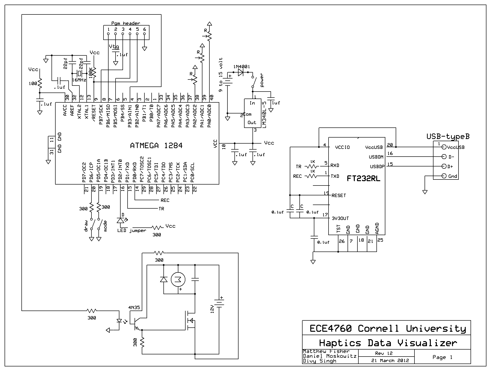
Schematic of Haptic Data Visualization. (Download Schematic.sch here)
C. Parts List
Most of the parts in this project were salvaged from previous projects in ECE 4760 lab and from scraps around the Gamma Alpha house. We had a budget of $100 and the final prototype is well under budget and came to a total of $26.38. The full pars list is shown below:
| Item | Source | Unit Price | Quantity | Total Price |
|---|---|---|---|---|
| ATmega1284 (8-bit MCU) | ECE 4760 Lab | $5.00 | 1 | $5.00 |
| Momentary button | ECE 4760 Lab | free | 2 | $0.00 |
| Potentiometer (10 turn) | ECE 4760 Lab | free | 3 | $0.00 |
| Wire | ECE 4760 Lab | free | a lot | $0.00 |
| LTE4206 | ECE 4760 Lab | free | 1 | $0.00 |
| LTE4208 | ECE 4760 Lab | free | 1 | $0.00 |
| LM358 | ECE 4760 Lab | free | 1 | $0.00 |
| BUZ73 | ECE 4760 Lab | free | 1 | $0.00 |
| 4N35 | ECE 4760 Lab | free | 1 | $0.00 |
| Resistors | ECE 4760 Lab | free | 3 | $0.00 |
| 9V battery clips | ECE 4760 Lab | free | 2 | $0.00 |
| Hot glue | ECE 4760 Lab | free | a lot | $0.00 |
| Capacitors | ECE 4760 Lab | free | 3 | $0.00 |
| 9V battery | Gamma Alpha | $2.00 | 2 | $4.00 |
| Pressure treated wood rods | Gamma Alpha | free | 3 | $0.00 |
| Eye hooks | Gamma Alpha | free | 3 | $0.00 |
| Nails | Gamma Alpha | free | a lot | $0.00 |
| String | Gamma Alpha | free | a lot | $0.00 |
| Vibration motor | Sparkfun | $4.99 | 1 | $4.99 |
| Oak dowel 1.25" diameter | Home Depot | $4.13 | 3 | $12.39 |
| Total | $26.38 |
D. Responsibility Breakdown
This project was completed in close conjunction with each team member contributing an equal amount. The general task responsibility breakdown is as follows:
Matt
- Hardware construction and testing
- Electronic hardware
- Website design
- Mechanical prototyping
Dan
- MATLAB animation
- Microcontroller/MATLAB communcation
- Hardware testing and debugging
- Object Mode
Divy
- User interface
- Microcontroller/MATLAB communcation
- Coordinate transformation
- Surface Mode
Acknowledgements
Special thanks to:
- Bruce Land for his patience and unfaltering willingness to help and MATLAB animation library.
- All of the ECE 4760 TAs for giving up countless evenings to staff the lab.
- Terry (Young Hwa) for being awesome and for her help early on in the project.
- Matt's co-op Gamma Alpha who graciously let us use their tools and scrap material.
- Christopher Atkins for chaffeuring us around and making countless trips to Home Depot.
- Michael Kilzer for helping us try find machine shop access and CSS advice.
- All those who has offered their help and guidance along the way.