Solar Powered Pulse Oximeter and Heart Rate Meter
Parin Dedhia (prd47)
 Introduction
Pulse Oximeter is a non-invasive medical diagnostic device used to detect the oxygen saturation of the blood. Heart rate meter detects the number of beats per minute of the patient, normally referred to as bpm. The pulse oximeter is designed using an infrared and a red LED, projected alternatively on the finger and detection of the transmitted light by a photodiode/phototransistor. The output of the photodiode is given to a transimpedance amplifier, and further amplified and filtered before giving to the Atmega644 microcontroller. The ADC in the microcontroller will convert it into digital form, and later display the value of SpO2 and heart rate on a 16*2 LCD screen. The goal of the project is to develop a low cost pulse oximeter and heart rate meter powered by solar energy. The idea was conceptualized due to the fact that the oxygen saturation of blood is one of the most important parameter to be monitored, and the pulse oximeter being low cost and solar powered, allows it to be accessed by the developing and under developed nations.
High Level Design/Background
Pulse oximetry has become a standard procedure for the measurement of blood-oxygen saturation in hospitals, clinics, etc. Pulse oximeter can directly detect hypoxemia, deficiency of oxygen saturation in the arterial blood. Early detection of hypoxemia can reduce the gas poisoning by CO2 or CO, tissue damage, etc. Thus, the oxygen saturation of the blood can quickly and accurately be monitored non-invasively using pulse oximeter.
Pulse oximeter works on the principal of absorption and reflectance/transmittance of light by multiple components like skin, muscle and blood vessel. Absorption due to tissue, skin or muscle remains fairly constant, whereas absorption due to arterial blood varies. Arteries expand due to the pumping of the heart, expanding the arteries and inturn increasing the tissue between the LEDs and the photodiode, thus increasing the light absorption. Using this principle, heart rate can be detected. Absorption of oxyhemoglobin and the deoxygenated hemoglobin form differs significantly with wavelengths (i.e.) oxygen is transported in the blood by hemoglobin, and, depending on the binding of oxygen to the hemoglobin, absorption of light takes place at two wavelengths as shown below.
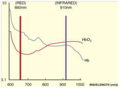 Figure 1: Absorption of oxygenated and non-oxygenated hemoglobin at different wavelength (http://www.oximetry.org/pulseox/principles.htm)
Light from two LEDs with different wavelengths i.e. 660 (RED) and 940 nm (IR) are made to fall on the finger. Oxygenated hemoglobin absorbs more infrared light and allows more red light to pass through. Deoxygenated hemoglobin absorbs more red light and allows more infrared light to pass through. The ratio of absorption at the two wavelengths is used to determine the fraction of saturated hemoglobin.
Pulse Oximetry can be done using two methods, reflectance oximetry and transmittance oximetry. In case of reflectance oximetry, the two LEDs and the photodiode are on the same side. Here, the light moves through the skin, muscle and blood vessel, and is reflected back from the bone. Reflectance oximetry has low signal to noise ratio and difficult to set up. In case of transmittance oximetry, the two LEDs and the photodiode are on the opposite side of the finger. Here, the transmitted light is detected by the photo diode, and is found to have higher signal to noise ratio.
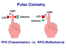
Both the approaches were tried in this project and it was found that the noise in case of reflectance method is higher as compared to the transmittance, also, the amplitude of the waveform is more in case of transmittance method.
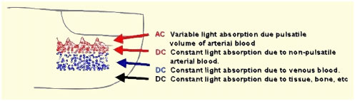
Figure 3: Absorption of light due to multiple components in finger (http://www.oximetry.org/pulseox/principles.htm)
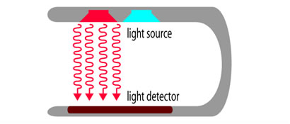
Figure 4: Emission of Red and Infrared LED on the light detector via the finger/tissue (http://www.equipmentexplained.com/physics/respi_measurements/oxygen/oximeter/pulse_oximeter.html)
The output of the photodiode is very less in amplitude, and also very noisy. Before giving to the microcontroller, high amplification and filtering is required to get the desired signal. Two band pass filters are used for the signal processing. The microcontroller is required to perform the analog to digital conversion of the signal, and calculate the peak amplitudes of the signal to generate the heart rate and SpO2. The values are displayed on a 16*2 alphanumeric LCD.
Background Math:
The ratio of the absorbance due to red led to that of infrared led can be formulated as:
R = ((Vmax(Red)-Vmin(Red))/Vmin(Red))/(Vmax(Infrared)-Vmin(Infrared))/Vmin(Infrared)
and oxygen saturation of blood can be formulated as:
SpO2=HbO2/(HbO2+Hb)
and
SpO2 = (10.0002*R^3 )-(52.887*R^2 )+(26.871*R)+98.283
Logical Structure:
Following is the logical structure/flow process of the project:
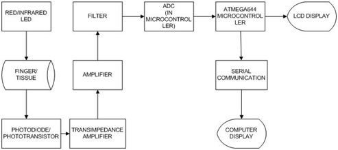
Figure 5: Block Diagram of pulse oximeter
Hardware/Software tradeoff:
1. The sensor probe does not have a flexible diameter, thus people with thicker finger might not be able to use this probe.
2. The charge capacity of the battery is not monitored currently.
3. Larger solar panel has been used currently, eventually a smaller panel will be incorporated.
4. Brightness of the LEDs is currently constant, complex algorithm can be incorporated in which the brightness of the LEDs will be determined by the thickness of the skin.
5. Too many wiring currently, shift to a printed circuit board will make the design more compact, with lesser wires.
Standards:
There are no standards that we need to worry about in this project.
Intellectual property:
There are no patents or copyrights associated with this project.
Hardware Design
The hardware design for this project can be divided into four major parts; sensor, amplifier-filter, microcontroller and power supply.
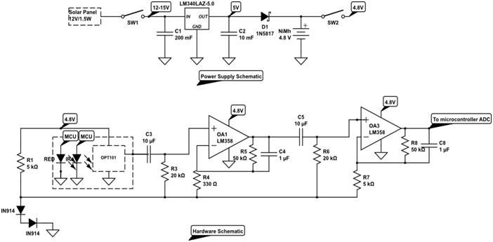
Figure 6: Hardware Schematic
1. Sensor: As discussed earlier, the sensor probe consist of a red and an infrared LED focused on the finger. The transmitted light through the finger falls on the photodiode/phototransistor. The variations in the blood volume causes variations in the light absorption and hence the transmission. The light source and the photo detector are placed on the opposite side of the finger. The ratio of the two absorptions will give us SpO2 value. The Infrared LED used was a LTE-4208 160-1029-ND Emitter IR 5 MM 940 NM Clear. OPT101 has been used as an integrated photodiode and transimpedance amplifier. It is a monolithic photodiode with on-chip transimpedance amplifier. Output voltage increases linearly with light intensity. The integrated combination of photodiode and transimpedance amplifier on a single chip eliminates the problems commonly encountered in discrete designs such as leakage current errors, noise pick-up, and gain peaking due to stray capacitance. Transimpedance amplifier is used to convert current into voltage, as the output of photodiode is current.
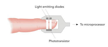
Figure 7: Transmission type pulse oximeter sensor probe (http://mikeandollie.wordpress.com/2011/04/30/childrens-memorial-day-14/)
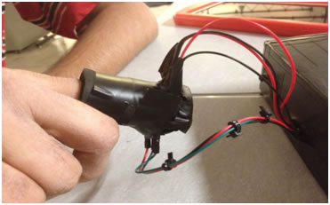
Figure 8: Inexpensive transmission type sensor for this project
2. Amplifier and Filter: We know that any bio signal has very less amplitude, and thus very likely to be super imposed by noise and interference hum. As the analog to digital convertor has high sampling rate, and can sample milli volts of signal, any kind of super imposed noise will disrupt all the readings completely, as even the noise will get sampled and will be digitized. Thus it is very critical and crucial for filtering the signal and get a pure noise free one. Also, for the efficient sampling and digitization, the analog signal must be amplified. Desired signals fall in the range of 0.1-3Hz, thus two band pass filters are used to eliminate all the signals except the band frequency of 0.7-3Hz. The gain for the first amplifier (A1) is set as about 150 and that for the second amplifier (A2) is 10. Thus total amplification A = A1*A2 = 1500. Dual packaged Operational amplifier LM358 chip has been used for the amplification and filtering as they are efficient, cost effective and were available in the lab.
3. Microcontroller: Atmega644 is an 8 bit microcontroller and has been used in the project. Atmega644 has 10 bit ADC which is used for sampling and digitizing the input analog signal. Hardware also includes the interfacing of the Atmega644 to the LCD display.
4. Power Supply: The goal of this project, as mentioned before, is to power this device using solar cells. 12V/1.5W solar panel was given by Prof. Bruce Land. The output current of the solar panel in bright sunlight is about 120mA. The solar panel is used to charge 4 NimH rechargeable batteries having charge capacity of 2500mA. Batteries are used to power the device during low light or no light conditions, i.e. when the solar panel is not efficient enough to drive the electronic circuit. The output of the solar panel is given to a decoupling capacitor of 0.2uF to filter out the high frequency noise. It is then given to a linear voltage regulator LM340LAZ-5.0 which gives out a constant DC voltage of 5 V. The output is further given to a decoupling capacitor of 0.01uF and later given to a schottky diode IN5817. A diode is very crucial element in the design, as it acts as reverse charge protection, i.e. it will prevent the battery to discharge backwards into the regulator and hence into the solar panel, thus avoiding damage to those. Schottky diode is used due to very low forward voltage drop, i.e. about 0.2-0.3V. The output of diode is about 4.8V and is appropriate in charging the rechargeable batteries. Two switches have been used, one in between the solar panel output and the voltage regulator and second between the output of the batteries and the Vcc terminal of main electronic circuit.
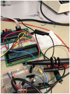
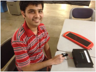
Figure 9: Hardware testing
Program Design
The program design consist of a few major parts. The samples are read in by using the built-in analog to digital converter (ADC) on the mega644. It performs a 10 bit analog to digital conversion based on a reference voltage (Aref). In this project, as the circuit ran on approximately five volt Vcc, so Aref was set to five volts. We know that ADC data registers are ADCH and ADCL, which are 8 bit individually and give a 16 bit register when used together. As the ADC in Atmega644 is a 10 bit ADC, he will give out only 10 bit of digital value. Since the least two significant bits of the ADC do not significantly affect the design, it has been ignored and the data has been stored in ADCH only. Twice of memory needs to be allocated, which cannot be afforded. To read two values from the ADC when needed, one would be read, then the ADMUX register changed to the other input, and then the program waited until the second conversion was complete. Due to these factors, I decided to use the ADCH register to store the 8 bit data. The analog signal is given to the default A0 pin of the microcontroller. The prescalar of the ADC is set to 128, giving us a frequency of 125KHz, very much in the ADC frequency range of 50-200KHz. The ADC is set in free running mode.
Timer 1 is a 16 bit timer/counter and has been used to perform interrupts every 0.01 second. As the frequency of the heart rate is about 1.2 Hz, 1/100 of that is chosen as appropriate for ADC to sample. Thus prescalar of 1024 has been selected in clear timer on compare (CTC) mode.
Calculations:
Required delay = 0.01 seconds
Clock = 16MHz
Prescalar = 1024
Thus, New frequency = Clock/Prescalar = 15625Hz
Timer count = (Required delay/Delay after prescaling)-1
= (0.01/(1/15625))-1
=155
Thus OCR1A is loaded with 155 and TCNT1 is initialized to zero. As the timer starts, TCNT1 will start counting up to 155, and on 155, an interrupt will be generated and ISR will be executed. As the ISR is generated due to timer1 compare, it is called as ISR(TIMER1_COMPA_vect).
UART has also been initialized to have a serial communication between the computer and the microcontroller.
The Maximum voltage and the minimum voltage is required to be calculated to find out the average as well as the ratio. The average is inturn used to determine the heart rate by counting the number of average crossings. The average is initially initialized to 60, a value determined by experimenting for the readings on a couple of people. 60 is a fairly constant value for almost every person's reading, i.e. a 60 on ADC is about 1.17V. Thus a crossing will be detected at every average value. The ISR will be executed every 0.01 second, and in ISR, we start loading the value of count in a variable lastcount, so that we have the value of current count as well as previous count all time. Then, as we know that ADCH has the 8 bit digital data, its value is loaded into the count. For checking and determining the maximum and the minimum voltage, we start comparing the maximum voltage (Pre initialized to 0) and the minimum voltage (Pre initialized to 255) with the value of the count, and start upgrading their values. Now, to determine the values of maximum voltage, minimum voltage, average and heart rate in a set period, we need to incorporate average crossing, and on having every average crossing, a variable c is incremented and loaded into d. Variable d is thus the number of ISRs executed. We know that time for one ISR is 0.01 seconds, thus frequency = 1/(0.01*d), and heart rate per minute is 60*frequency. Also, after determining the maximum and minimum voltages, the ratio x is calculated and used in the SpO2 formula to give its value.
Results
The project was quite successful. The values of the heart rate and SpO2 were verified with that from the graphs on the oscilloscope, and were almost the same. Here are a few pictures of the results:
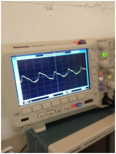
Figure 10: Oscilloscope display of the signal
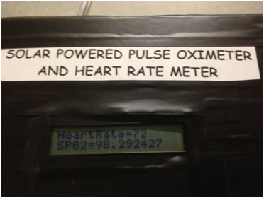
Figure 11: Heart rate and SpO2 results display on the device
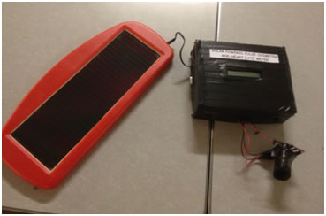
Figure 12: Fabricated product
Figure 13: Testing of the project
The results were stable and matched with that from oscilloscope's. The results were checked during panting condition, and the heart rate boosted up to 105, and gradually settled for 75-80 over 5 minutes. The project does not have any safety concerns due to low input power. The product is well fabricated and easy to use, just switch on the power and push your finger in the sensor, the display will show you the readings. The device drew about 60mA of current, and as the charge capacity of the batteries is about 2500mAH, the device will run efficiently for over 40 hours, which is exceptionally good time duration. Also, assuming 120mA of current from the solar panel in bright sunlight, it will take about 20 hours to charge the batteries completely, which is fairly reasonable.
Conclusion
The project was a success. The Heart rate and SpO2 for me was on an average 80 beats per minute and 98.23% respectively. The heart rate for normal person is about 72 beats per minute and a normal range is about 60-90 beats per minute. The SpO2 for normal person lies between 95-99%. SpO2 below 94% may be fatal and may cause unconsciousness. The device was designed efficiently and met all expectations as set earlier. Due to shortage of time, the charge capacity of the batteries could not be monitored and displayed on the LCD. The current sensor probe is not flexible for a thick finger, and can be made much more flexible. More complex algorithm can be written to change the brightness of the LEDs with variation in the skin thickness. Smaller solar panel could not be bought, and its inclusion will make the project really robust and ready to use in any environment. As mentioned earlier, the device has a capability of running for over 40 hours, which will really revolutionize the health care in under developed and developing nations which has many electricity problems. With higher charge capacity batteries, time duration for its usage can be made longer.
IEEE Code of Ethics
I accept responsibility in making decisions consistent with the safety, health, and welfare of the public, and to disclose promptly factors that might endanger the public or the environment by performing experiments safely, and when in doubt consult a TA or Prof. Bruce. As my device is low powered, there are no issues pertaining to experimenting with high voltage. I had no real or perceived conflicts of interest and worked in harmony. I have been honest and realistic in stating claims or estimate based on available data, and have shown results as per the experimentation. I am not involved in bribery in all its forms. Over past couple of weeks, I have been constantly trying to improve the understanding of technology; it's appropriate application, and potential consequences by studying various research papers, asking for TAs or Prof. Bruce for help and other fellow students. I readily seeked criticism from TAs or Prof. Bruce for any technical incompetence and worked over it to rectify error and mistakes. I was un biased with respect to race, religion, gender, disability, age, or national origin. I did not cause any injury to a person, or loss to the property or employment by false or malicious action.
Appendix A: Code
#define F_CPU 16000000UL //16MHz crystal
#include <inttypes.h>
#include <avr/io.h>
#include <avr/interrupt.h>
#include <stdio.h>
#include <avr/eeprom.h>
#include <util/delay.h>
#include <stdlib.h>
#include <string.h>
#include <avr/pgmspace.h>
#include "uart.h" // serial communication library
#include "lcd_lib.h" //lcd library
const int8_t LCD_initialize[] PROGMEM ="\0";
int8_t lcd_buffer[17]; // LCD display buffer
int8_t lcd_buffer1[17]; // LCD display buffer
FILE uart_str = FDEV_SETUP_STREAM(uart_putchar, uart_getchar, _FDEV_SETUP_RW); //UART initialization
volatile int max, min,a,b,count,c,d,average,lastcount;
float HeartRate,Vmax,Vmin,x,y,z;
float value=0.0158;
void timer1_init()
{
TCCR1B |= (1 << WGM12)|(1 << CS12)|(0 << CS11)|(1 << CS10); // set up timer with prescaler = 1024 and CTC mode
TCNT1 = 0; // initialize counter
OCR1A = 155; // initialize compare value
TIMSK1 |= (1 << OCIE1A); // enable compare interrupt
}
void init_lcd(void)
{
LCDinit(); //initialize the display
LCDcursorOFF(); //no cursor
LCDclr(); //clear the display
LCDGotoXY(0,0); //go to x and y position on the lcd
CopyStringtoLCD(LCD_initialize, 0, 0);
}
int main()
{
ADMUX= (0<<REFS1)|(1<<REFS0)|(1<<ADLAR); //AVcc as reference voltage and Left shift bits
ADCSRA=(1<<ADEN)|(1<<ADPS2)|(1<<ADPS1)|(1<<ADPS0)| (1<<ADATE); //Prescalar 128 and set bit for free running mode
ADCSRB= (0<<ADTS2)|(0<<ADTS1)|(0<<ADTS0); //Free running mode
init_lcd();
timer1_init(); //timer 1 initialization
average=60; //initialize average value for average crossing detection
max = 0; //initialize maximum =0
min = 255; //initialize minimum = 255
sei(); //Global interrupt enable
UCSR0B = _BV(TXEN0); //Serial transmission
UBRR0 = 103;
ADCSRA |= 1<<ADSC; //start conversion
stdout = stdin = stderr = &uart_str; //UART transmission
LCDclr(); //clear lcd
CopyStringtoLCD(LCD_initialize, 0, 0); //copy the string data to position x=0, position y=0
while (1)
{
z=1/(0.01*d); //calculation of frequency of ISR
HeartRate=z*60; //calculation of heart rate (beats per min)
fprintf(stdout,"HeartRate=%f \n",HeartRate); //UART transmission of heart rate
CopyStringtoLCD(LCD_initialize, 0, 0);
_delay_ms(2000);
sprintf(lcd_buffer,"HeartRate=%2.0f ",HeartRate); //sending heart rate values to lcd for display
LCDGotoXY(0, 0); // goto position x=0, position y=0
LCDstring(lcd_buffer, strlen(lcd_buffer));
sprintf(lcd_buffer1,"SP02=%f ",y); //sending SpO2 values to lcd for display
LCDGotoXY(0, 1); // goto position x=0, position y=1 (second row)
LCDstring(lcd_buffer1, strlen(lcd_buffer));
PORTD=0b00000001; //blinking led every 4 ms
_delay_ms(4);
PORTD=0b00000000;
_delay_ms(4);
PORTD=0b00000010;
_delay_ms(4);
PORTD=0b00000000;
_delay_ms(4);
}
}
ISR(TIMER1_COMPA_vect)
{
lastcount=count; // copying value of count into last count used for average crossing (becomes previous value_
count = ADCH; //copying value of ADCH into count (current value)
//we checking for maximum and minimum value for analog input
if(count>max)
{
max=count; //if current value in count is greater than maximum value, then copy it to maximum
}
else if (count<min)
{
min=count; //if current value in count is less than minimum value, then copy it to minimum
}
c++; //counter increments
if((lastcount>average) && (count<average)) //average crossing condition
{
average=((max+min)/2); //average calculation
a=max;
b=min;
fprintf(stdout,"a=%i\n",a); //UART transmission
fprintf(stdout,"b=%i\n",b);
x=value/(a-b); //calculation of ratio
fprintf(stdout,"x=%f\n",x);
y=(10.0002*x*x*x)-(52.887*x*x)+(26.871*x)+98.283; //calculation of SpO2
fprintf(stdout,"y=%f\n",y);
d=c; //copy counter value to d
c=0; //clear counter
fprintf(stdout,"d=%i\n",d);
max=0; //clear max
min=255; //clear min
}}
Appendix B: Schematic can be found in the hardware section
Appendix C: Parts List
| Part |
Cost ($) |
| Atmel Atmega 644 |
Free (Previous year's board) |
| Solder Board (*2) |
$5 |
| LCD |
Free (Borrowed) |
| Max233CPP |
Free |
| RS232 Connector |
$2 |
| Infrared LEDs and Red LEDs |
Free (From Lab) |
| Solar Panel |
Free (From Prof. Bruce) |
| Resistors and Capacitors |
Free (From Lab) |
| NiMH Rechargeable Batteries |
Free (Borrowed) |
| LM358 Opamp |
Free (From lab) |
| LM340LAZ-5.0 regulator |
Free (From lab) |
| 2 pin flat jumper cables (*10) |
$10 |
| OPT101 photodetector |
$6.93 |
| Switches |
Free (From lab) |
| Diodes |
Free (From Lab) |
| Total |
$24 |
Appendix D: Division of Labour
As this was a individual project, whole project has been made by me.
Appendix E: References
I am really thankful to Prof. Bruce Land and all the TAs for their help for the final design project.
Datasheet:
1. OPT101: http://www.ti.com/lit/ds/symlink/opt101.pdf
2. Atmega644: http://www.atmel.com/Images/doc2593.pdf
Vendors:
1. Texas Instruments: http://www.ti.com/
2. Atmel Corporation: http://www.atmel.com/
Online references:
1.http://homepages.cae.wisc.edu/~bme300/pulse_oximeter_s09/reports/Pulse_oximeter_midsemester_report.pdf
2. http://cache.freescale.com/files/32bit/doc/app_note/AN4327.pdf
3. http://hackaday.com/2010/01/06/pulse-oximeter/
4. http://people.ece.cornell.edu/land/courses/eceprojectsland/STUDENTPROJ/2008to2009/cc464/FINAL_REPORT.pdf
5. http://www.analog.com/library/analogDialogue/archives/41-01/pulse_oximeter.html