
Introduction
Our goal in this project was to build a pair of high-speed transceivers that could encode and decode optical signals modulated using Morse code conventions.
The project involved a few interesting challenges that we believed would be interesting to tackle. Interfacing a camera with a microcontroller is a difficult thing to do, due to the limited memory capabilities of most microcontrollers. Because of the limitations imposed, in order to properly use a camera with a microcontroller, resources must be intelligently applied and the circuit must be designed around the camera rather than the microcontroller. The project took shape around the idea of a optical endec transceiver because it demonstrates how you could design an algorithm to process the image data from a camera without a prohibitive amount of memory being used.
In the four weeks that were allotted to us to finish this project, we built two high-speed transceivers that take user input (via PuTTy), encode the sentence(s) into a Morse code sequence, and flashes its associated transmission LED accordingly. The other station uses its camera to snap many pictures in succession of the other's transmission LED, and in counting the number of 'dark' versus 'light' frames, decodes the Morse code and displays the reconstructed sentence on its corresponding computer screen. A few special considerations that came up during the design process was the coordination scheme between the two stations. Since both stations have receiving and transmission capability, to limit collisions (which would result in mangled data) and/or incomplete transmissions, we designed a simple protocol that limits when a station can receive and transmit.
High Level Design
Due to processing limitations, we changed the direction of the project in the middle of the design period. Originally, we planned to design a line-detection algorithm using noisy data from actual outdoor environments, but after gauging the resolution of the data that could be procured with our camera (and the very limited memory resources of our microcontroller), we decided that such an idea would not be feasible with our current camera and microcontroller.
Therefore, we decided to choose an application that depended less heavily on image quality. After discussing alternatives with several other people (Bruce Land, Annie Dai, Samuel Anttila), we decided to design and build a Morse code endec transceiver. Logically, the design is relatively simple, and the behavior of each transceiver can be broken down into three parts, as summarized in the graphic below.
Transmitter/LEDs
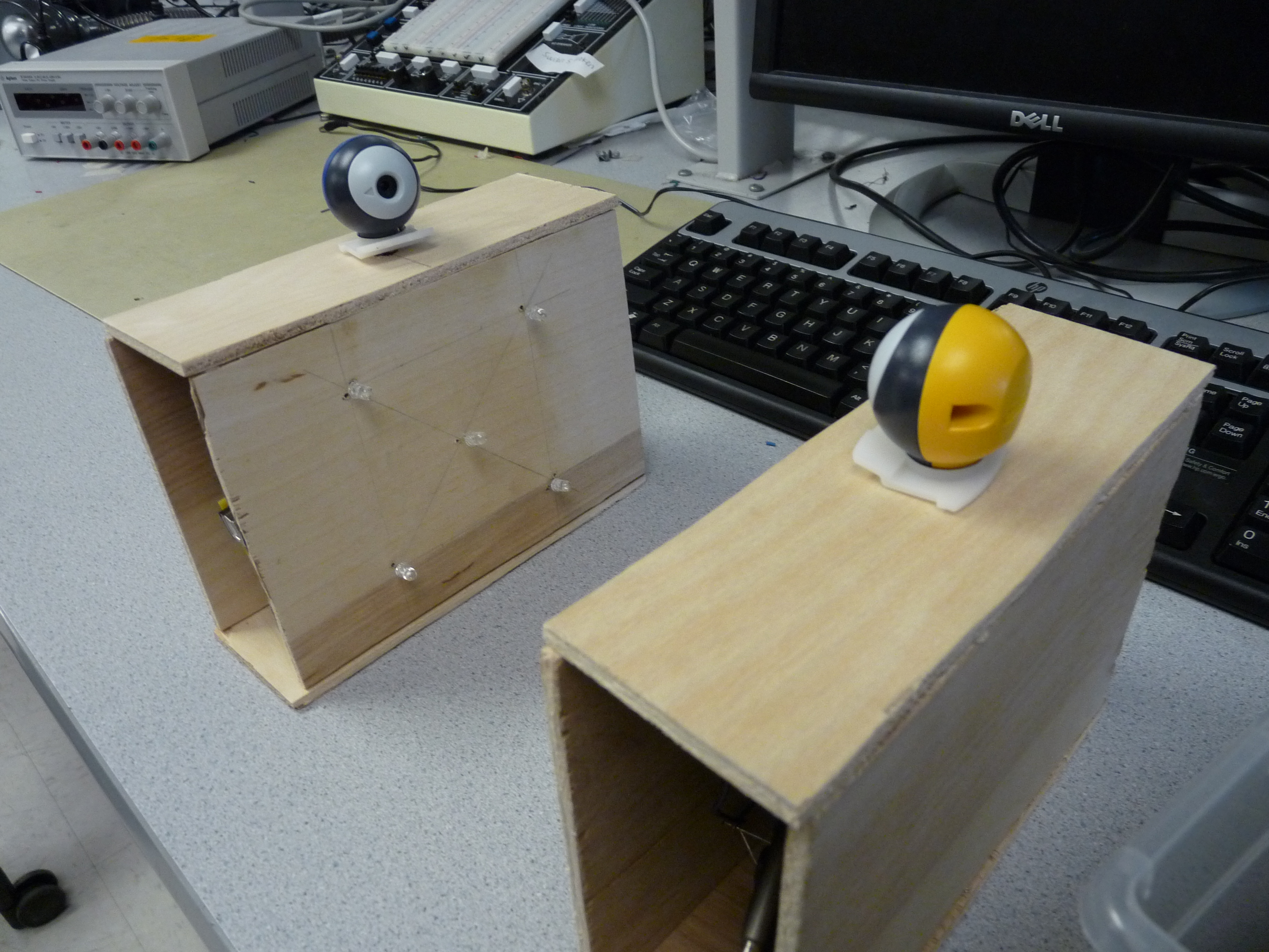
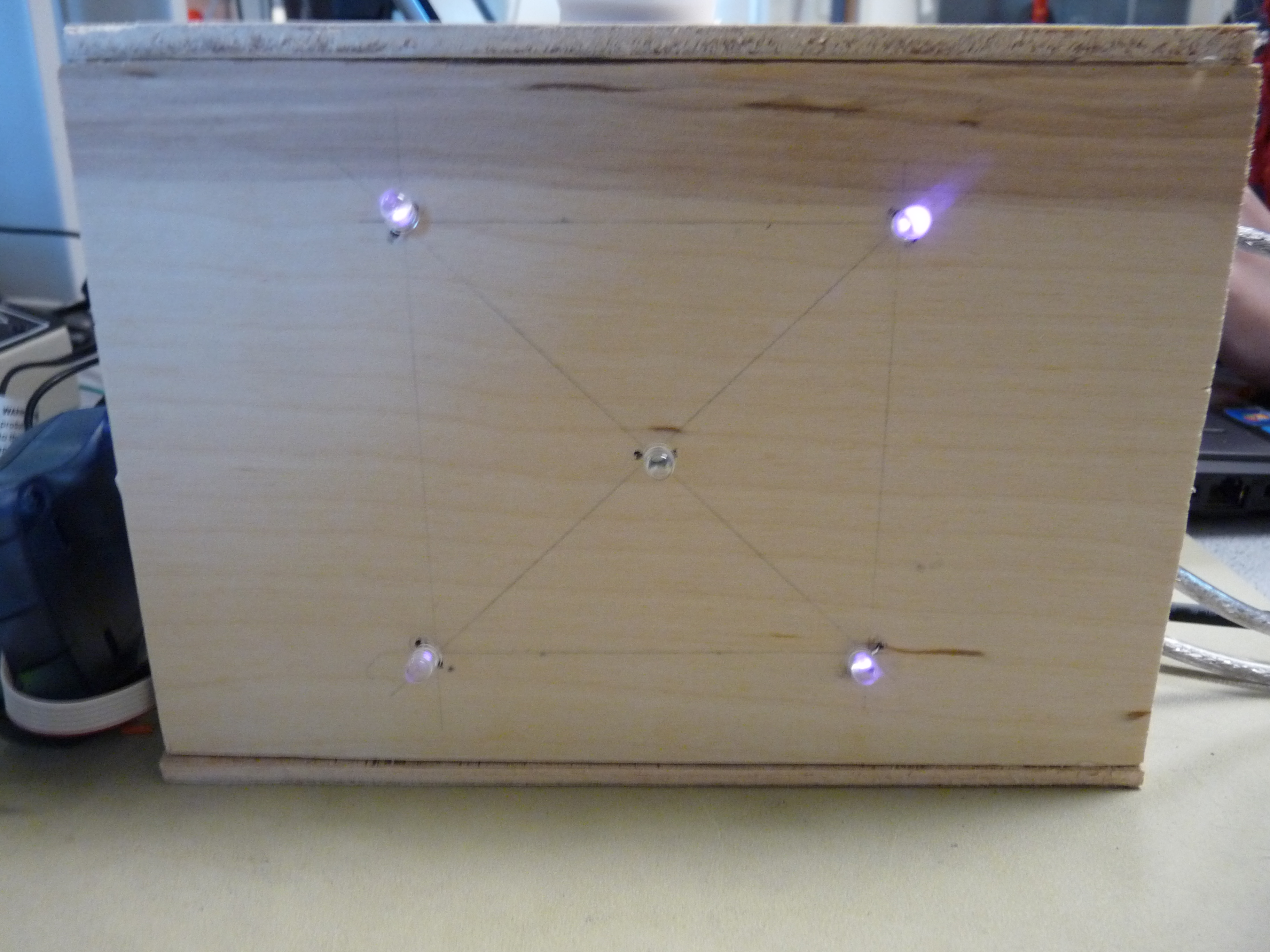
The transmission functionality is implemented using a Mega1284 microcontroller and five high-intensity IR LEDs. To form a unique pattern for the receiver to recognize (and to ensure that the transmission LED is always in frame), four of the IR LEDs were arranged into a square; these LEDs are almost always on. The IR LED at the center is the transmission LED; the microcontroller modulates the light in accordance with the Morse code conventions.
Receiver/Camera
Likewise, the receiving functionality is implemented using the same Mega1284 microcontroller (used for transmission) and a M64282FP image sensor, which we left encased in the original Gameboy Color camera so we could take advantage of the lens. Since the possibility of additional light sources (besides the transmission LED) is very likely, especially in longer-distance applications, the camera detects the LED frame before searching for and reading the transmission LED (of the other station). The pattern of light flashes can be decoded by counting the number of frames that are dark (and light). Once the entire passage has been decoded into its respective Morse code, the pattern is matched it to a Morse code library and displayed on the screen at one time.
Transmit/Receive Protocol
To enable both transceivers to transmit and receive without loss of data, a simple receive/transmit protocol was designed and utilized. A transceiver can either transmit or receive; we decided to eliminate the possibility of doing both at the same time. For simultaneous receiving and transmitting, multithreading would have been necessary, which would significantly slow down our camera operation. Since decoding is dependent on a fast camera frame rate, multithreading would have constrained us to a much slower maximum LED blink speed.
Therefore, to coordinate the two modes of the transceiver, we need a signal that alerts the other transceiver that it is receiving/transmitting. In the case that A is the transmitter and B is the receiver, the protocol is as follows:
- When A wants to send, it sets all its frame LEDs bright.
- When B sees a frame, it turns on its own frame.
- Starting at this point, B cannot ask to transmit its own message.
- When A sees the frame, it sends a calibration signal (a dot followed by a dash, equivalent to the Morse code message "et").
- When B sees the calibration signal, B counts the number of bright frames it has captured.
- A then begins to transmit and B begins to receive.
We performed a few back-of-the-envelope calculations to gauge the feasibility of this project. Our goal was to increase transmission via Morse code to the point that ordinary people could not look at the blinking LED and decode it faster than the microcontroller (for obvious reasons). For this to occur, we would need a very fast camera frame rate to decode the dots and dashes accurately. If each character takes an average of three dashes, and each word has about five characters, and each sentence has about ten words, then the average sentence would be about 3x5x10 = 150 dashes. If we want to take about 5 seconds to transmit the sentence, then each dash must be about 0.03 seconds long, which means that each dot must be about 0.01 seconds long, which translates to a frame rate of 90 frames per second, assuming that each dot can be accurately captured in one frame of the camera. Since this is much much much faster than our camera can support, it was likely that something on the order of 10-15 second transmission would be achieved.
To ease the load on the software, we set up our physical display so that any complicating external factors, such as external light sources, were mostly eliminated. The hardware/software tradeoffs that we mostly looked at during project design included eliminating the use of an ISR (to reduce code complexity); the hardware bits that directly controlled the camera were set using a simple sbi() command after the appropriate amount of time had elapsed, which made the code very simple and very fast. The _delay_us command was used for this purpose, since after the threshold hold time is met, the exact time is not of much importance. Furthermore, because of the very limited memory of the Mega1284 chip, the data from the camera had to be stored in memory in a very compact format. Although we used the unsigned char data type for the majority of the variables to save space, a char array consisting of 16384 elements would still have exceeded the memory capacity of the microcontroller. Therefore, in software, a few lines of code were written to quickly and effectively create a bit array to store the digitized values of each pixel.
Our design falls under a more general class of devices that utilize free-space optics. Because this technology is not yet very prevalent, there are not very many standards governing the design of such devices. However, IEEE 802.15.7 details the standards for a very similar technology, visible light optical communication. This document provided valuable guidance to us during the design process: it shaped our consideration of the modulation process and led us to consider the possible topologies of our device.
As far as we know, our project does not violate any copyrights. Although there are several VLC systems that are on the market, our modulation scheme (chosen to support a slow camera framerate) and transmission/reception protocol are unique.
Hardware Design
The hardware that we used in our project is as follows:
- two Mega1284 microcontrollers
- two M64282FP image sensors (complete with lens)
- ten high-intensity IR LEDs
- resistors: 6x 330Ohm, 4x 2kOhm, 2x 1kOhm
Each transceiver consisted of one microcontroller, five high-intensity LEDs, one M64282FP image sensor (inside the Gameboy Camera), and one 200 Ohm resistor.
Gameboy Camera
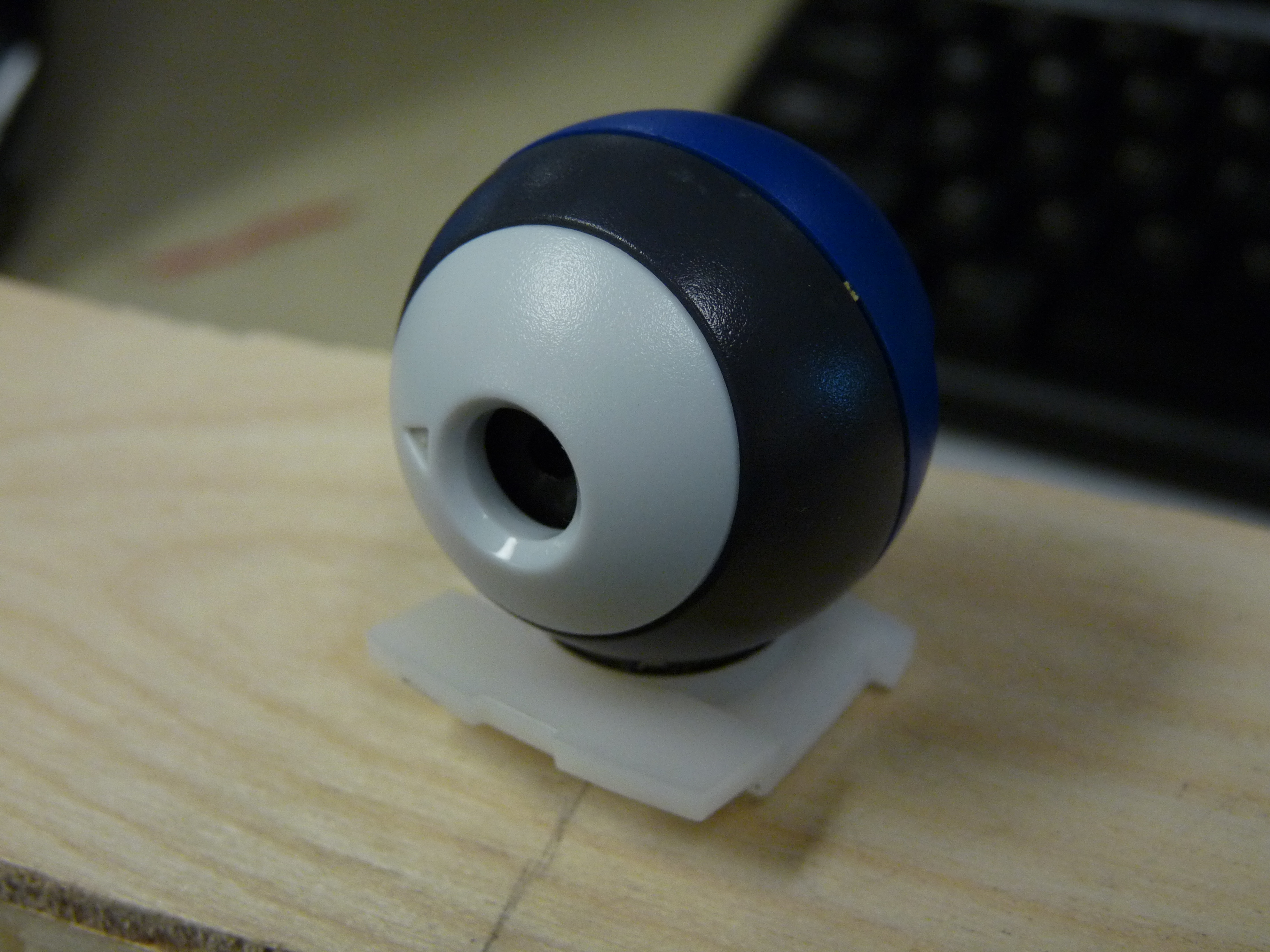
Several resources were consulted [1][2] when interfacing the Gameboy Color camera with the microcontroller. The M64282FP image sensors are unique in that they already come interfaced with a CMOS chip that does elementary image processing (therefore cutting down on the thresholding processes that needed to be performed on the microcontroller, which allows for greater operation speed). Furthermore, this camera/chip ensemble has a clear datasheet and iis well-documented in many hobbyist AVR groups, which increased its attractiveness.
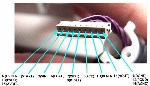
The Gameboy Camera comes attached to a Gameboy cartridge; in order to make use of the camera, we had to disassemble the cartridge and remove the camera head. Fig. 1 shows the order of the exposed wires at the base of the camera head. After we had ascertained the order, we carefully cut the plastic wire holder away, one wire at a time, and soldered these wires carefully (in order!) to a set of pins that would allow us to interface to the microcontroller via a target board. This was done to streamline the testing process- in the finished project, the camera leads were cut from the pins and soldered directly onto the board for a neater appearance.
The camera was then connected to PORTC of the microcontroller: the output of the camera (VOUT) was fed into Port B.2, the input of the MCU's comparator. The remainder of the camera outputs/inputs (START, SIN, LOAD, RESET/XRST, XCK, READ) were attached to Ports C.2 - C.7. START,SIN, LOAD, RESET, and XCK are camera inputs, while READ is a camera output.
Analog Comparator
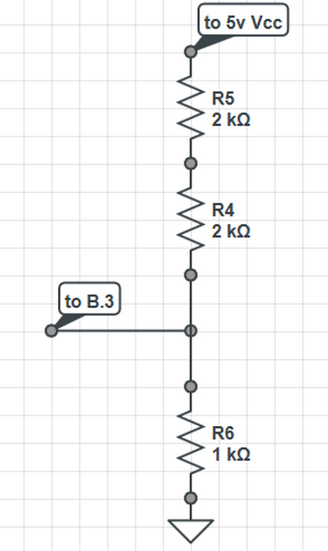
The output of the camera was then fed into the on-board analog comparator. The Mega1284p projected a delay of 1-2 clock cycles to convert from the input to the output, which we needed to take into account when acquiring the values from the comparator AC0 bit in software. The comparator compares the analog output of the camera with the reference voltage appearing at Port B.3; this reference voltage was set using a simple voltage divider, as diagrammed below.
IR LEDs
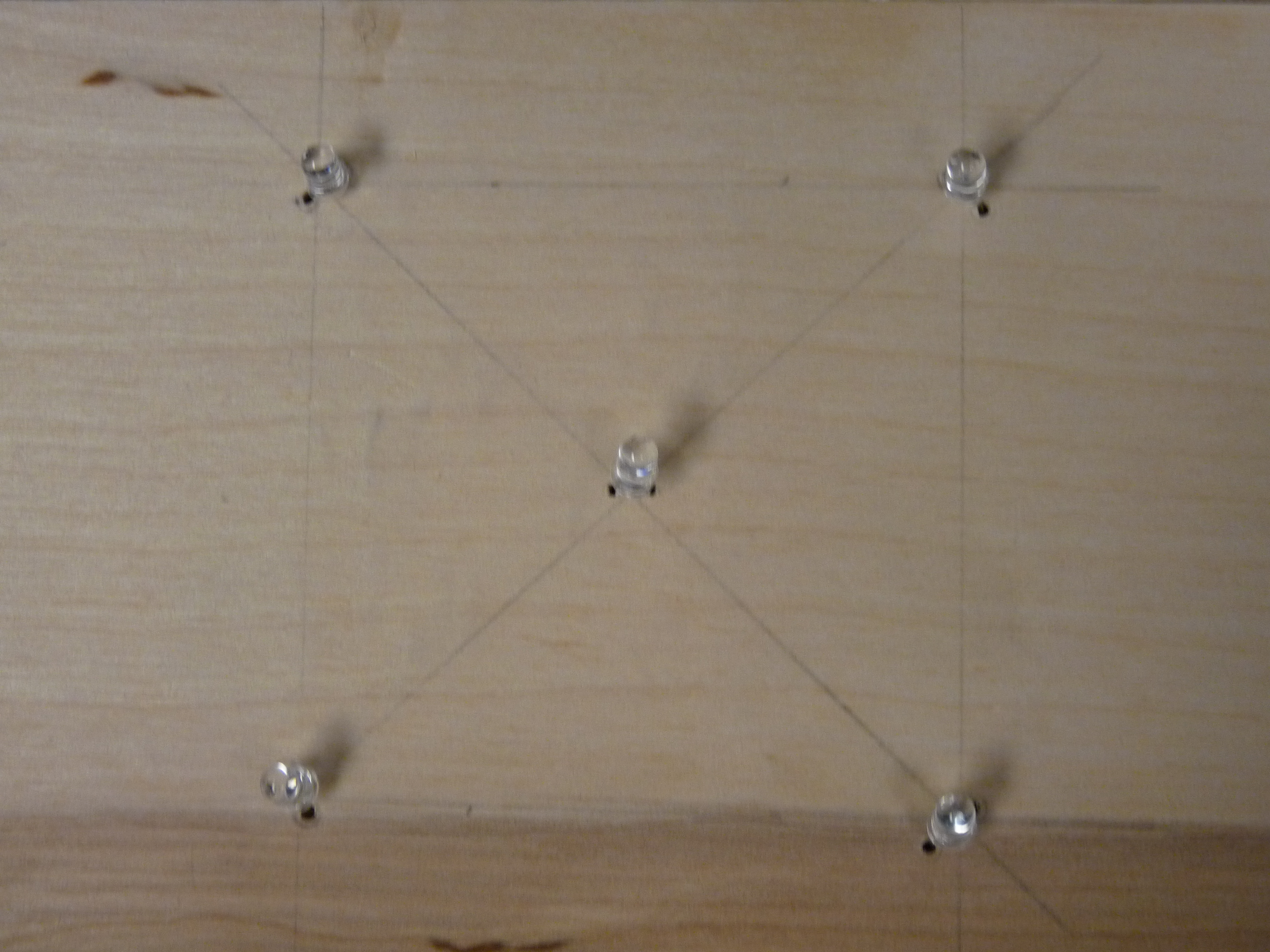
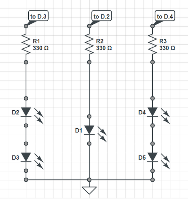
In order to facilitate good alignment between the two transceivers (and maximize accuracy of the transmission), five high-power IR LEDs were associated with each transceiver. Four of these LEDs were arranged in a rectangle (dimensions: " by "), which formed a 'frame' for the transmission IR LED, which was placed in the center. The frame was designed to be easily recognized (even with the microcontroller's limited capacities) and differentiable from unwanted lighting noise which could also be present. Another purpose that the frame serves is for cross-communication between the two transceivers. Since the Morse encoding requires timing to be synced between the two transceivers (which may run at different speeds), cross-communication allows the transceivers to relate the speed of the other station to their own. The top two LEDs are connected in series to Port D3, while the bottom two LEDs are connected in series to Port D4. Originally, we had wanted to connect all the frame LEDs in series, but disappointingly, the the IR LEDs became too dim for easy detection when that configuration was attempted. Although controlling each pair of LEDs separately made our code a little more complex, it ensured that our LEDs were of sufficient brightness for detection.
The center LED (transmission LED) has a function that is self-explanatory: it transmits the Morse-encoded message that is typed into PuTTy by the user. This LED is connected to Port D2.
After we had tested that the circuits were correct, we removed the circuits from its white board and resoldered them on a solder board. We then encased the majority of a system in a wooden box; the camera was propped at the top of box, and the LED patterns were embedded into the front panel of the display, which ensured that the spacing would not inadvertently change during operation.
Software Design
Transmit
The goal of the transmit functions is to receive user input (in the form of a string) using PuTTy, encode that using Morse code conventions, and translate the code into a series of bright flashes that will be output on the transmission LED, all the while following our transmission protocol. That is, it must first turn on all its frame LEDs to signal that it will transmit, wait for the other transceiver's acknowledgement, and then send a calibration signal (a dot followed by a dash) to the receiver. Only after this is complete does the transceiver begin to transmit its message using its transmission LED.
The actual data transmission process was relatively simple. An ISR was used to divide the 16 MHz clock by 10, and this slowed-down clock was then further processed in waitOneUnit() to form an arbitrary 'unit' of time, which was used as the smallest unit of the Morse encoding.
sendDot():
This function sends a dot, or the smallest flash of light that is significant according to the Morse encoding: it has a duration equal to the unit of time generated by waitOneUnit(). This was done by first raising the LED_BIT (the bit of the port corresponding to the transmission LED), waiting for one unit, and then lowering the LED_BIT. Since the spacing between each Morse segment for one letter is equal to one unit of time, we wait for another unit before leaving the function.
sendDash():
This function sends a dash, which is a flash of length equal in length to three units of time. This was done by first raising the LED_BIT (the bit of the port corresponding to the transmission LED), waiting for three units, and then lowering the LED_BIT. Like in sendDot(), since the spacing between each Morse segment for one letter is equal to one unit of time, we wait for another unit before leaving the function.
sendSpace():
This function ensures that the spaces between words has a duration of seven units. This function waits for four units, since the other three units of waiting occur at different parts of the program.
input():
This function is primarily in charge of acquiring input from the user. It first clears the message array, cmd[200], and waits for the user's input via fgets(), which copies the user's input via the UART into cmd[200]. This function then forwards the message array to transmit(message) for Morse encoding.
transmit(message):
This function takes the message array from input() and steps through each the array (not counting the newline at the end of the array), sending each separated character to transmitLetter(letter).
transmitLetter(letter):
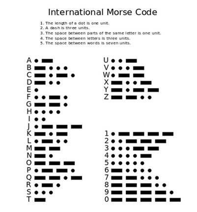
This function is where the real Morse encoding takes place- the function consists of an exhaustive library which translates from either the uppercase or lowercase letter to its corresponding sequence of dots and dashes, which is summarized in this excellent reference from [5].
After every letter, we send an additional two waitOneUnit() intervals of time, which makes a total of three units of time between every letter, which adheres with the Morse conventions.
Receive
The receive functions allow the transceiver to use its camera to view the other transceiver's pattern of LEDs. Upon detecting a fully bright frame, the receiver flashes its own frame momentarily (which serves as an acknowledgement) and immediately waits for the transmitting side to send the calibration signal. Once it receives the entire calibration signal (including the "end-calibration signal", it waits for the message. Once the entire message has been received, the message is decoded and displayed on the receiver's computer screen via PuTTy.
detectFrame():
Both the transmit and receive side use this function to make sure that the cameras are aligned properly and can see the IR LEDs facing each other. The function searches a picture for a 2x2 rectangular array of bright spots that are at least 3x3 pixels wide/high. The tilt of the frame is determined by a changeable variable (ie. the frame doesn't not have to be perfectly symmetric to be detected). Furthermore, if the camera happens to detect multiple bright spots that qualify as frame points, the code will take the largest frame possible. If no frame is detected, the function will recursively call itself and remain in an infinite loop until detection is complete.
detectLED():
This function utilizes the frame detection from above to search for the LED sending the Morse code signal. The algorithm will only search within the frame for a blinking LED, thus slightly speeding up the process, typically only having to look through a 70x70 pixel window (4900 total) rather than all 128x123 (15744). Once an LED is detected to be on for a long enough duration (set by THRESHOLD), a variable LED_on is flipped to 1.
displayMessage():
This is where a long message is parsed into separate letters by identifying the appropriate signals in the message array:
- 'a' - signals a dash
- 'd' - signals a dot
- 'm' - signals a space between signals of the same letter
- 'l' - signals a space between signals of different letters
- 's' - signals a space between signals of different words
This function separates out letters separated by the 'l' or 's' signal and stores the individual letter information in a ltr array to be processed by decodeLetter(), below.
decodeLetter():
Similar to the transmit side, this function holds a library for decoding Morse code signals for individual letters. For example, the letter 'a' is represented by a dot followed by a dash, which translates to "d-m-a" in the key described above. The function uses the built-in C function memcmp to compare the letter arrays with those stored in this library, printing the appropriate translation to PuTTy.
receive():
This function calls the various methods above to form a complete receiver. Two variables, posFrame and negFrame, hold information about for how many frames the LED has been bright and dark, respectively. Using Morse code conventions, the function stores the appropriate 'a,' 'd,' 'm,' 'l,' or 's,' signal into the message array (ie. 3 units time of posFrame represents a dash while 3 units of negFrame represents a space between letters). As a safety measure, the function will also continuously check that the frame is in sight, else it will attempt to detectFrame() again.
Camera
Both the transmitting and receiving sides make use of a camera to detect each others' signals.
The M64282FP image sensor has a very specific communication protocol that is SPI-like, but since it was likely that configuring the MCU to use SPI to communicate to the camera would lead to at least some loss in functionality, we took a look at a previous group's project [4]. Although we originally wanted to use their code, we discovered that the maximum operation speed possible with the code would be too slow for our application, due to the ISR that was used to control timing. However, reading their project gave us many insights into designing our new camera protocol- their code was well-organized and provided us with general guidelines with which to structure our own code.
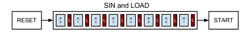
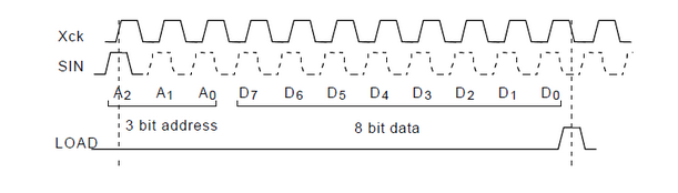
The camera requires a specific sequence of input commands to configure correctly, as diagrammed in Fig. 4. After resetting the camera (through the RESET line), each of the camera's eight programmable registers (R0-R7) must be written sequentially through the SIN line. After each register write, the LOAD signal (denoted by the red boxes in Fig. 4) must be toggled. After the last write, the START input to the camera must be toggled.
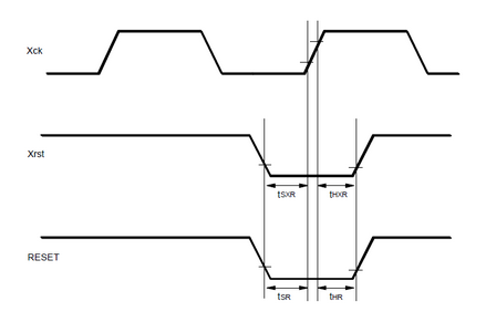
The timing requirements of the RESET, SIN, LOAD, and START were detailed in the M64282FP datasheet, as seen in Figs. 5-7. Due to the sequential nature of the signals and the nonexistent timing constraints between each discrete input command, the program was written so that each signal is controlled by its own function. Furthermore, because the chip does not constrain the XCK signal to be constant-width (just that the minimum period should be 8 us), to control timing, we used a clock that followed the data (rather than vice-versa). We programmed for this by manually setting the signal LOW or HIGH after the correct CLK state is achieved/occurs. Since all the camera functions modify XCK to force the correct timing, the program mirrors the current logic state of XCK in a global variable, state, so that upon starting, every function knows the XCK that the last function left off on. This reduced the complexity of the timing considerably; in fact, the only thing we needed to consider was the amount of time before and after the XCK edge for which the signal needed to be held constant.
reset():
The first signal to be sent to the camera is the RESET signal, which is active LOW and is sampled on the rising edge of the XCK signal, which is also generated by this function. Since RESET is active LOW, the RESET pin is set HIGH when the program is initialized. The sequence of events is then as follows: if the XCK is high, then XCK is lowered. A 10 microsecond delay is then introduced (using the avr/delay library) before RESET is set LOW. After another 10 us delay, RESET is set high. Due to the implementation, this toggles the RESET bit and places the rising XCK edge squarely in the middle of the toggle operation, thus ensuring that the timing requirements are always met.
sin() and load(): The sin() function writes all eight registers of the camera, and the load() function toggles the LOAD signal every time a register has been written. Therefore, it follows that after every time sin() writes one register, it calls load(). SIN is an active HIGH signal and is read at the positive edge of the XCK signal, while LOAD is read at the negative edge of the XCK signal. For both functions, the timing is done in a very similar manner as reset(). For sin(), if XCK is not already LOW, XCK is set LOW. After a brief delay, SIN is set HIGH, another brief delay is generated and XCK is set high. Another delay is then applied, which ensures that the next function will not force XCK down too quickly. Since each register consists of 11 bits (the first 3 bits give the address of the register, and the last eight bits encode the contents of that register), this process occurs 11 times for each register. After the 11th time, load() is called, and the entire function loops until all eight registers have been copied to the camera. The only difference between toggling the SIN bit and toggling the LOAD bit (on the XCK) is that SIN is read on the rising edge of XCK, while LOAD is read on the falling edge of XCK.
start():
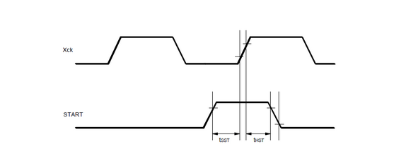
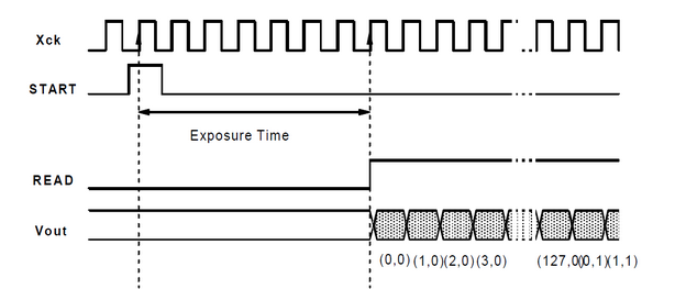
The start() function toggles START exactly like sin() toggles the SIN bit. This signal signals the camera to snap a new frame, and it is unique in that we only have to generate the first START pulse (after configuration has completed). Afterwards, the chip on the camera will continue to generate the START pulses for all subsequent frames.
For this reason, all of the above steps only need to be performed once.
Once the camera had been configured and camera operation starts, the next step is acquiring the data from the camera. When the camera begins to release image data (in the form of consecutive pixels), the camera sets the READ signal HIGH, which signals to the MCU that the image data is being shifted out with every rising edge of the XCK. The timing considerations inherent to this operation are illustrated in Fig. 8.
camRead():
Since the outputs are continually updated whether or not we need the result, it would be ideal if we could choose to capture only one frame at a time. For this reason, we wrote a dedicated function, camRead(), to start pixel capture once the camera output READ goes from LOW to HIGH. The associated flag read_Finished limits the capture to the subsequent 128x128 = 16384 pixels: once this number of pixels has been written to an array in memory, the flag goes HIGH and both the pixel-reading loop and the function terminate. This allows us to both save on memory write operations and increases the speed with which the camera operates. Basically, every time that the XCK signal is LOW (we can check this by checking the status of the state global variable), we set the XCK signal to HIGH and immediately read the READ output of the camera. If READ is HIGH (and the previously acquired value of READ is LOW), then the rising edge for READ has been detected, signalling that the camera has begun to output image pixels. Henceforth, we read the ACO bit of the ACSR register for the comparator (after a small delay to let the output data settle) and pack it into a global bit array, picture[]. (Initially, we tried to use a char array to hold all 16384 pixels, but the microcontroller ran out of memory- we were actually unable to get the UART working!) If the READ signal remains LOW, the only thing the function does is toggle the XCK bit, which allows the camera to accurately measure its required exposure time.
getPixel(x_coord, y_coord):
Within the transmit and the receiving part of the code, we seldom dealt with the entire array, since extracting the data from the bit array could prove to be messy, especially when lumped with other code. This function was used to do the extraction, which improved the overall readability of the code. getPixel simply returns the value of the pixel at (x_coord, y_coord), which it extracts by doing some simple arithmetic: the uint32_t (computer-addressable) address of the pixel is (128*y_coord + x_coord)/8, while the more specific bit address of the pixel can be found to be (128*y+coord + x_coord)%8.
Design Results
Our results are pretty successful. We can transmit messages of between around 200 letters at a time (depending on the equivalent Morse code length of the letters used) at 10-12 frames per second. There may be occasionally one or two inaccuracies due to the LED blinking precisely during the offt-ime of the camera processing the frame, resulting in a '~' character to appear in the message (for example, 'ap~le' may show up as opposed to 'apple'). This is not a frequent occurrence and may be fixed given a camera with a faster frame rate. However, the receiver code is able to work in pretty much any situation independent of hardware.

Conclusions
This project has been successful. but many improvements can probably be made. Although our library is consistent with Morse code, being able to process the 36 alphanumerics (a-z, 0-9), it may be interesting to develop more other signals to display a wider variety of characters. Currently, our code also depends on hardcoding some parameters such as camera exposure time, which affects the maximum distance between the stations that may be achieved (ie. higher exposure time may allow greater distance, but may also introduce more noise). Coding improvements may also speed up our current camera's framerate, allowing for faster transmission.
All codes of ethics were followed in the design and creation of this project. All shared code is properly accredited. The use of Morse code is part of the public domain. There is no harm to people nor property during the use and construction of our project. The messages transmitted and received are fully dependent upon the user. This project encompasses topics learned in ECE 4760, from basic C programming to circuit construction. The use of our code is free and encouraged, as is any criticism to our project.
This project follows all the IEEE Code of Ethics lines. There is no aspect in this project that is harmful to any individual and the community. The conflict of interest is involved in this project since rock paper scissors game is simple and fair. The game is made so that any individual can play and no form of bribery is involved in this project, since the computer gives hands randomly. The project improves the understanding of technology in the way that it combines computer vision algorithms, which are usually computationally extensive, and low cost microcontrollers. We have acknowledged all the sources of help in this report and we are more than willing to accept any criticism on our work.
Appendices
Appendix A: Budget and Parts List
| Part | Source | Unit Price | Quantity | Total Cost |
|---|---|---|---|---|
| Total | -- | -- | -- | $68 |
| Gameboy Camera/M64282FP Image Sensor | Ebay | $10 | 2 | $20 |
| Mega1284p MCU | ECE4760 Lab | $5 | 2 | $10 |
| IR LED | ECE4760 Lab | $1 | 10 | $10 |
| Serial UART Extension | ECE4760 Lab | $4 | 2 | $8 |
| Header Pins | ECE4760 Lab | $0.05 | 100 | $5 |
| Sockets | ECE4760 Lab | $0.05 | 100 | $5 |
| Plank of plywood | Lowe's | $10 | 1 | $10 |
Appendix B: Schematics
Appendix C: Code Listing
Appendix D: Distribution of Tasks
- Morse Encoding
- Camera Integration
- Frame/LED Detection
- Final Report
- Website Design
Trudy Chu
- Morse Encoding
- Morse Decoding
- Frame/LED Detection
- Final Report
- Circuit Soldering/Construction
Josh Sun
References
Datasheets
Atmel ATMega1284p Microcontroller
M64282FP Image Sensor
Background Sites/Paper
[1]The Autonomous Driving Car, by Bonnie Chong, Rick Yan, Albert Li
[2]Implementing Vision Using a GameBoy Camera on the MRM
[3]International Morse Code standards
Acknowledgements
We would like to thank Bruce Land and Annie Dai for all the debugging help and support.