
Introduction
Top"An encrypted laser-based friend-foe identification system to prevent friendly fire in battle"
This project implements an Identification Friend-or-Foe (IFF) system for use by soldiers to prevent friendly-fire. The inspiration for the project is derived from Identification Friend-or-Foe (IFF) transponder systems currently used on fighter aircraft and military vehicles. Fighter aircraft fitted with an IFF system transmit a coded radio (RF) message to other aircraft detected within a pre-set range. Friendly aircraft can decrypt the RF message and provide a correctly encrypted response to prevent fratricide
Each soldier’s rifle is fitted with a laser that sends out an IFF query. If a friendly soldier is in the line of sight of such rifles, the IFF system produces a feedback signal. This signal can be used to generate an audible/visual warning, or to momentarily jam the rifle.
High Level Design
TopRationale
Incidents of friendly fire have been responsible for numerous casualties amongst soldiers. Such incidents, caused by a variety of reasons including miscommunication and aggressive battle tactics, represent an opportunity to minimize the human cost of war. NATO forces in Afghanistan have encountered a more sinister form of friendly fire in the form of disgruntled Afghan soldiers or disguised Taliban militants. Afghanistan’s Soldiers Step Up Killings of Allied Forces, an article published in the New York Times on January 20, 2012 provides a more detailed description of the problem. Our IFF system applies a tested method of preventing friendly fire in a new scenario, and has the potential to save lives.
System Architecture
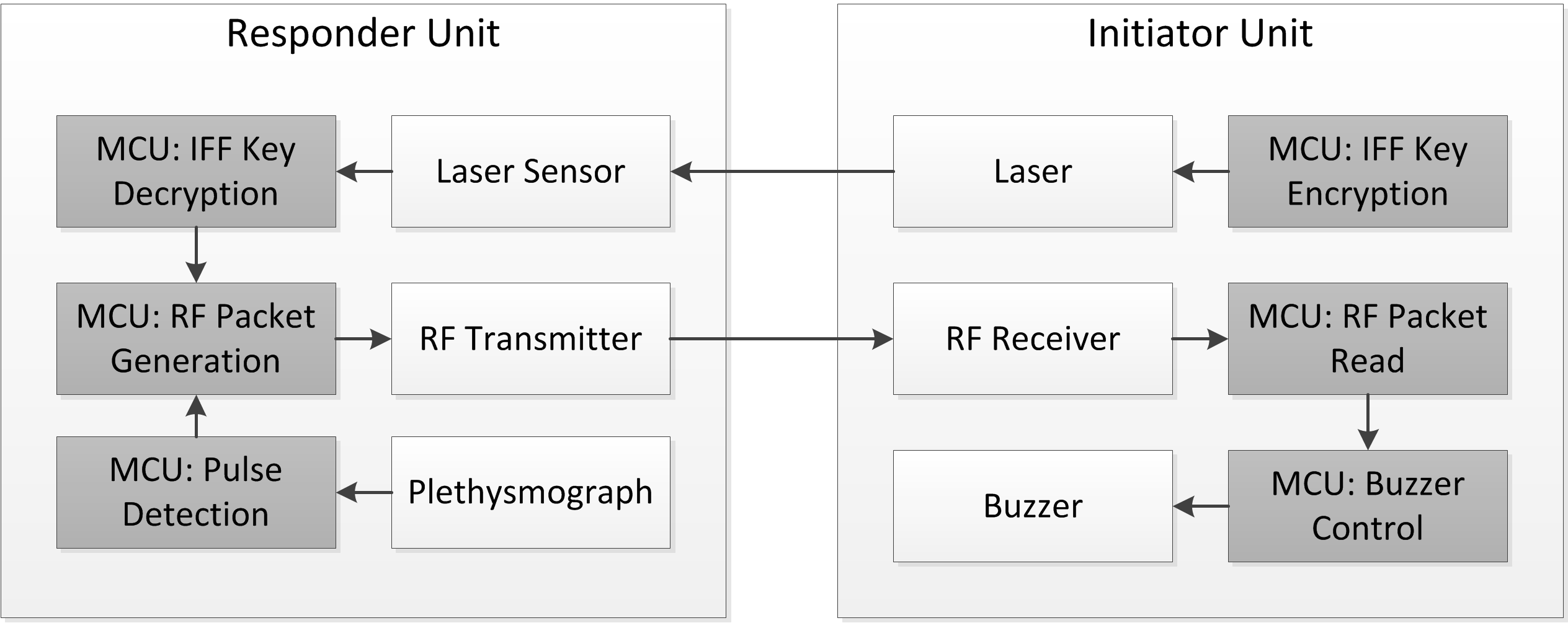
Figure 1: System Architecture
The grayed boxes in Figure 1 are parts of the system implemented in software on a microcontroller unit (MCU). The white boxes are implemented in hardware. A soldier equipped with the IFF system has a responder unit on their body armor, and an initiator unit mounted on their rifle. The rifle module uses a laser to transmit an encoded message – the IFF query. If the rifle points toward a friendly soldier, phototransistors mounted on the target soldier’s body armor will detect an incident laser beam. An MCU in the responder unit will decrypt the laser message using a pre-set private key. If decryption is successful, the MCU identifies which friendly soldier is currently aiming at the target soldier, and broadcasts this information in RF. RF receivers in the initiator units of all friendly soldiers within firing range parse this information to determine if the rifle they are mounted on is pointing toward a friendly soldier. If potential fratricide is detected, a buzzer mounted on the rifle goes off, signaling that the current rifle position might result in friendly fire. This feedback signal used to trigger the buzzer may also be used to prevent the next round from being loaded in the weapon’s firing chamber.
The IFF system has two major fault cases:
- Hostile forces may try to masquerade as friendly forces by detecting the laser IFF query and responding with an RF broadcast. A pre-set private key encryption system is used to prevent hostile forces from decrypting the IFF key. A similar encryption system can be used to safeguard RF communications. This problem must be handled by generation of secure keys, and at the operations level by regular key changes like IFF systems currently in operation in fighter aircraft. Our prototype uses a trivial encryption scheme for the laser IFF query and no encryption for the RF messages in order because it is designed to be a proof of concept only.
- Hostile forces may recover the responder modules of the IFF system from dead soldiers and use it to masquerade as friendly soldiers. A plethysmograph monitors the soldier’s pulse. If the heart rate falls to zero, the MCU in the responder unit can wipe its program memory to deny use of the unit to hostile forces. A similar scheme can be implemented to prevent hostile forces from using the initiator unit on rifles. Our prototype implements the plethysmograph system on the responder unit only, and turns on a red LED instead of wiping program memory.
Hardware/Software Trade-offs
Laser vs Directed RF
Our initial design concept used a directed RF signal on the rifle instead of a laser to transmit the IFF query. Using an RF signal would have made encryption easier. If the RF signal transmitted from the rifle was sufficiently directional, the IFF query would have been sent only to RF receivers in the line of the rifle’s fire. This scheme would allow IFF queries to be sent to soldiers who were in the rifle’s line of fire, but not line of sight because they were blocked by an opaque object like a door.
We explored a ‘cantenna’ and custom axial mode helical antennas to produce a sufficiently directed RF signal. Helical antennas were too expensive to be viable for mass deployment, and the cantenna failed to attenuate the RF signal sufficiently in directions other than the line of fire. We decided that the inherent coherence and collimation of a laser compared to a directed RF signal outweighed the disadvantage in encryption schemes.
Diverging vs parallel Laser Beam
The responder unit detects laser beams incident on a soldier’s body armor using phototransistors. In order to protect the entire back and torso of the soldier, the IFF system requires either a large laser beam or a lot of phototransistors on the armor. We chose to use a large laser beam to minimize the circuitry needed for the body armor. A large parallel laser beam could be generated by placing a concave lens followed by a convex lens after the laser. This approach preserves the collimation of the laser beam and increases the distance over which the IFF system can prevent friendly fire. The convex lens would have to be quite large, and therefore expensive to get a sufficiently wide laser beam. We use only the concave lens and sacrifice range in the prototype to decrease monetary cost.
Real Time Operating System vs Manual Scheduling
We use a real time operating system to schedule tasks in the MCU software. Manual scheduling would allow quicker competition of software tasks. The relatively simple laser and RF communication, and slow time constants of human reaction and the human heart rate all make the speed of execution of the code less important. Hence we use the operating system to facilitate easy creation of tasks.
Consolidating Received Signal
Each vest can have up to 50 phototransistors, depending on the sensor density desired. Although it might be possible to do a software-based polling loop, we decided to keep a minimal pin count by using diodes to build a simple OR-gate. This provides the advantage of allowing the gate output to drive an interrupt, which is more efficient than a polling-based method.
Standards
UART
The Universal Asynchronous Receiver/Transmitter (UART) protocol forms an important part of our project, since we use UART to send signals to our wireless transceivers, which in turn enables cross-device communication. We also use it heavily while debugging the project by using the UART for serial communication over USB with a console on a PC. This enabled us to look at the internal state of the microcontroller throughout execution.
FSK/CSMA: FCC Regulations for RF
The IFF system uses a wireless module that transmits data on the 915 MHz frequency spectrum. Although it is used as a black-box component, we understand that it uses the Carrier Sense Multiple Access (CSMA) protocol to control wireless transmissions, and the wireless signal is encoded in a frequency-shift keying (FSK) modulation scheme. The wireless modules are compliant with international regulations, including FCC and ETSI.
ANSI Z136
The IFF system uses a 2.5mW Class 3A laser. According to the ANSI Z136 standard, lasers of this class can damage the retina if looked at directly for over two minutes. The beam diameter is less than 1 sq. cm, hence it doesn’t need protective eyewear for normal operation.
IFF Federal Standard
IFF is defined by the Federal Standard 1037C as:
Identification, friend or foe (IFF): A system using electromagnetic transmissions to which equipment carried by friendly forces automatically responds, for example, by emitting pulses, thereby distinguishing themselves from enemy forces. [JP1] Note: The secondary surveillance radar (SSR) system used in modern air traffic control systems is an outgrowth of the military IFF system used during World War II. The IFF equipment carried by modern military aircraft is compatible with the transponder system used for civilian air traffic control.
Software
TopFriendly Fire Detection | User Validation | Collision Avoidance | Real-Time Operating System
Friendly Fire Detection
When a laser beam is detected on any one of the vest's phototransistors, the hardware circuitry generates an interrupt on the INT0 pin. We use a software timer to keep track of the intervals between consecutive interrupts; every transmission module will have a unique interrupt interval to ensure that each module is identifiable based on the received signal. Since the interval detection is accurate up to 50 microseconds, we can assign each transmission module a unique millisecond interval. This makes false identification very unlikely. If the laser period falls within any of the valid ranges, the software recognizes that the user is in danger of friendly fire, and will transmit a wireless signal to the offending initiator module. The initiator module buzzes the user upon receipt of the signal; when the laser leaves the sensor and the calculated laser period changes again, the responder unit will send a "cease" signal to the initator unit to stop the buzzing.
User Validation - Plethysmograph
We use a plethysmograph to ensure that the IFF system will be deactivated immediately upon separation from the user. Each pulse from the user generates an interrupt, which resets a software-based watchdog timer. If the timer count exceeds a predetermined amount, it indicates that the system has been detached and it will wipe the program memory to prevent fraudulent use by imposters. In our demo, we substitute the wiped-out state with an LED that turns and remains on (even after power cycling) to show that the system can perform as described, without us having to reprogram the target board every time this occurs.
The program memory can either be wiped with the chip erase command by setting the command byte to 1000 0000, or by overwriting program memory.
Collision Avoidance
One limitation of the system is that friendly fire detection is done on a narrow electromagnetic spectrum. This means that multiple laser signals arriving at the same receiver will cause the signals to overlap and potentially generate an invalid registration, rendering the system not working. Although one option is to use a different part of the electromagnetic spectrum for each transmitting laser module, we quickly determined that it was too costly and unfeasible. One solution is to create a sparse signal, such that the laser is only activated once every few milliseconds. This ensures that when many lasers can be pointed at the receiver at once, each individual signal pattern will still be detected. Because the period between signal firings will differ across various transmit modules, we are confident that each signal will eventually have a period of time where it can register against the receiver. We can further improve collision management by having an exponential back-off period upon collision, similar to that in the CSMA protocol.
Real-Time Operating System
System Overview
We use the TinyRealTime (TRT) kernel system to schedule our various software processes and ensure that deadlines are kept. This helps us abstract away the complexities in managing multiple tasks that need to execute while UART communication is ongoing. The TRT system also provides semaphores to ensure mutual exclusion when accessing shared resources such as the UART channel across different processes.
Task Configuration
Initiator Module
The inititator module only has one task, laser_recv, which sets up the laser signal and checks periodically for a friendly-fire signal from the responder unit.
Responder Module
The responder unit has the following three tasks:
- setup_send: Checks the frequency of interrupts from the input sensors, and sends a "friendly-fire" signal to the initiator unit. Once the frequency falls outside the valid range, it sends another "cease" siganl to the initiator unit to indicate that it can resume normal operation
- plethys: Sets up the analog interrupts for the plethysmograph, and checks if there is a pulse rate within the last 4 seconds. If not, light up an LED to indicate system will be unresponsive (in the field, the system will erase its memory)
- check_plethys: A task to debounce the analog interrupts from the plethysmograph
Hardware
TopOverview | Initiator Unit | Responder Unit | Plethysmograph | Microcontroller | Wireless Communication | Power Source
Overview
Our system is divided into two components - the responder unit and the initiator unit. Although each individual will be equipped with both the responder and initiator unit, they are functionally separate and do not interact with each other during normal operation.
Initiator Unit
The initiator unit generates a laser signal along the weapon's line of firing. The microcontroller generates a PWM signal that operates a MOSFET switch, which in turn regulates the laser output. This creates a laser beam that appears to be steady to the observer, but is actually a very rapid series of pulses with an interval unique to each soldier.
Laser Divergence
One challenge we faced was to ensure a suitable beam spread as the distance from the module increased. Too wide a spread will cause the system to trigger even when the weapon's line of fire does not go near a friendly soldier, but too narrow a spread might cause the beam to fall in the gap between phototransistors on the user's vest, resulting in a false negative. We want our 4mm diameter laser to obtain a diameter of about 60cm at 10m range to cover at least the chest area. This translates to a divergence angle of tan-1(0.60/10) = 3.43 degrees. When choosing our concave lens, we then use the formula for calculating divergence:
divergence = tan-1 ( beam width / focal length )
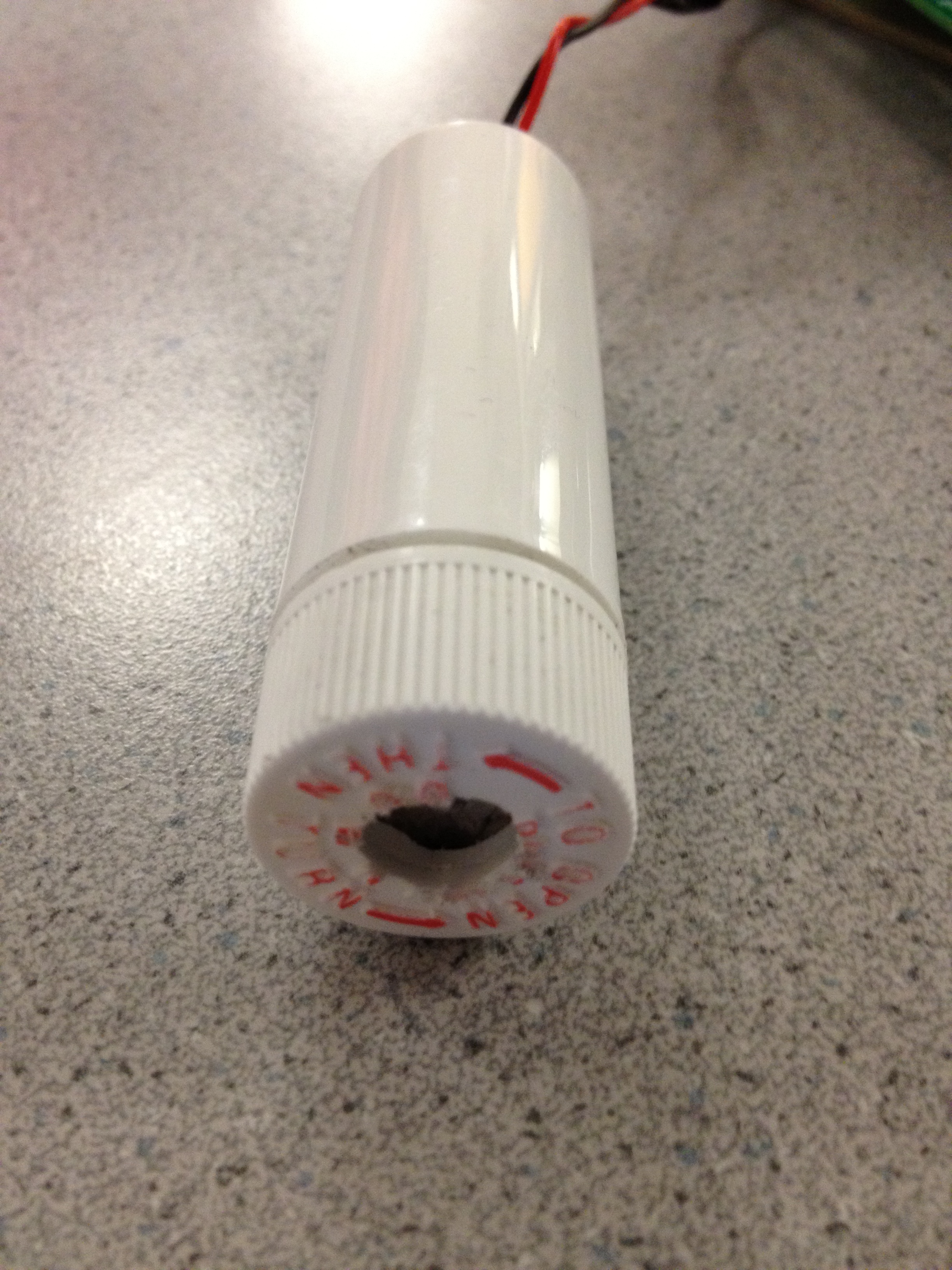
Where the beam width is the diameter of the laser incident upon the lens, and the focal length is an absolute value (since concave lens have negative focal lengths). Using the formula, we determined that we needed a concave lens with a focal length of -65mm to achieve the necessary divergence. Since the laser module did not fit well with the lens that we purchased, we created a small housing for the module using an empty Tylenol capsule container. After removing the wrapper and drilling holes for the laser and wiring, we had a robust laser module.
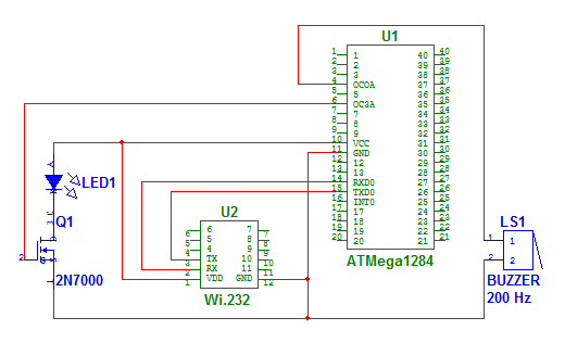
Buzzer
The buzzer, when activated, is driven using a simple 200Hz PWM output from the ATMega.
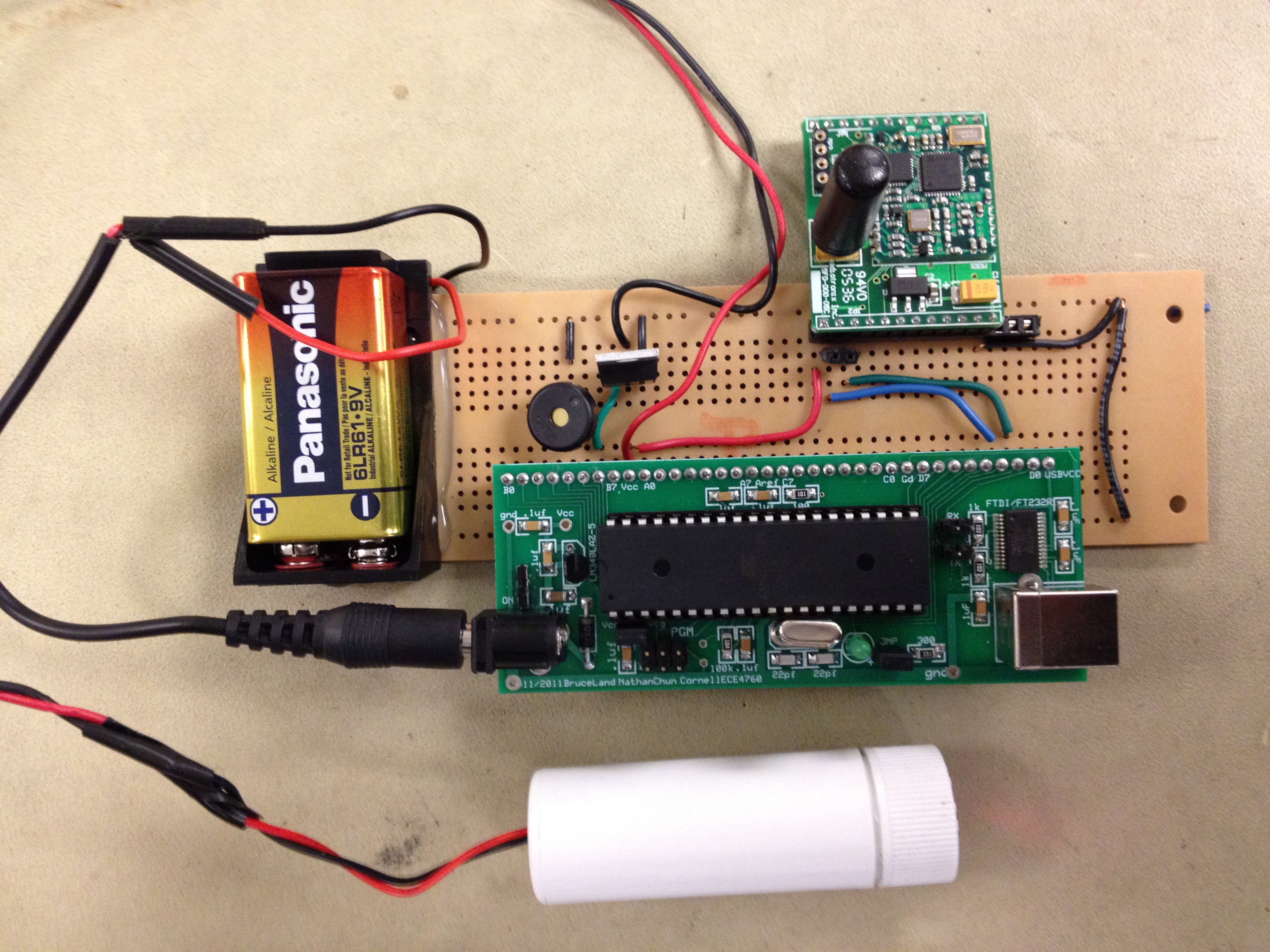
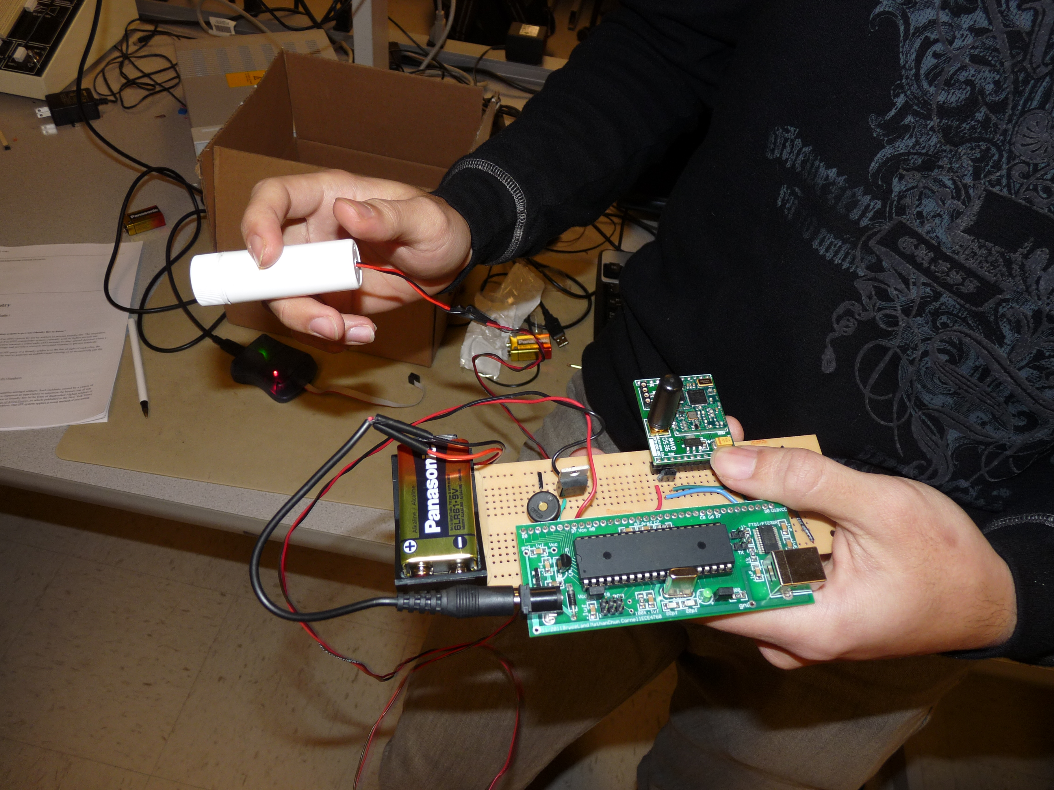
Our completed initiator module is showcased below:
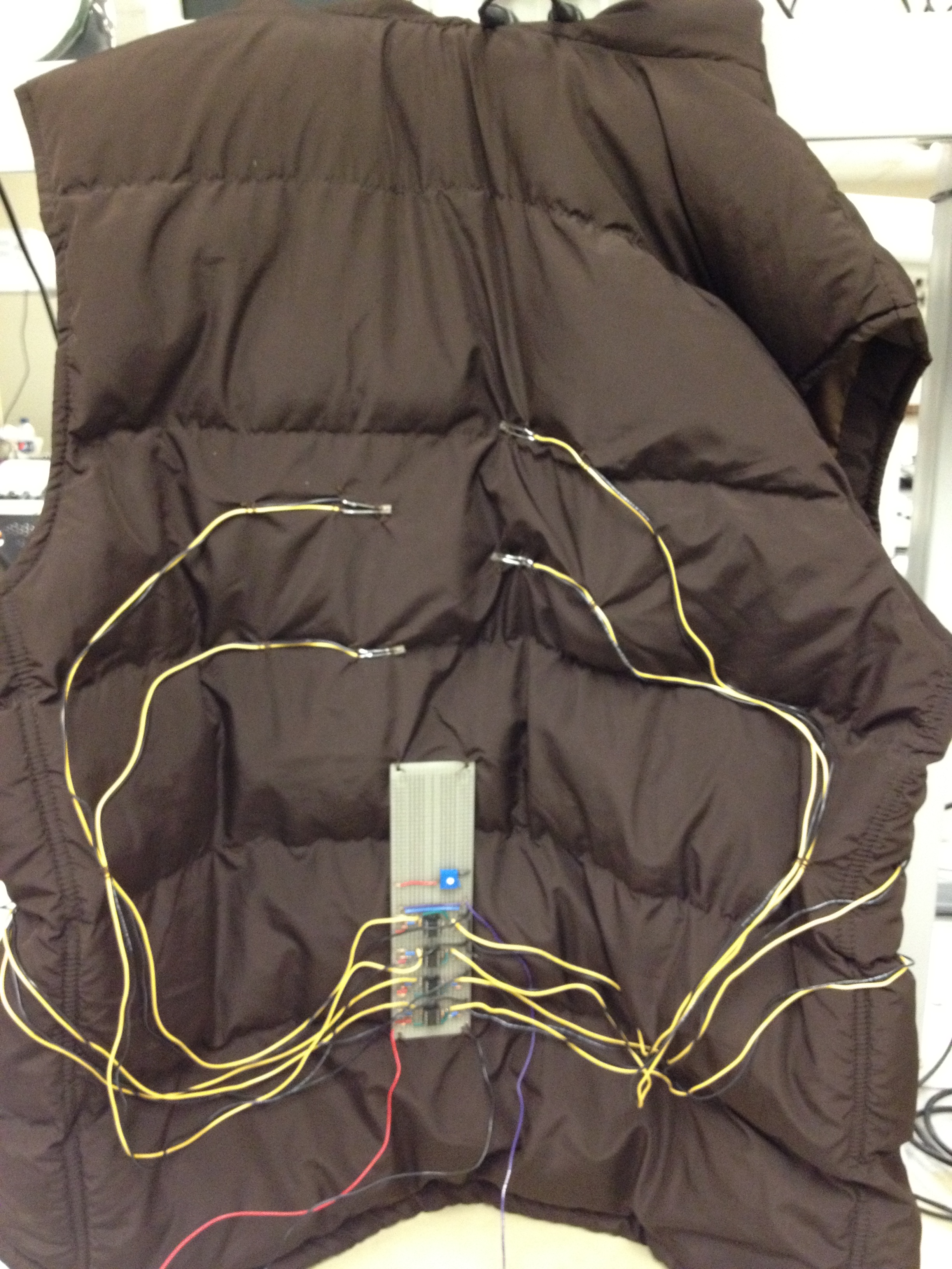
Responder Unit
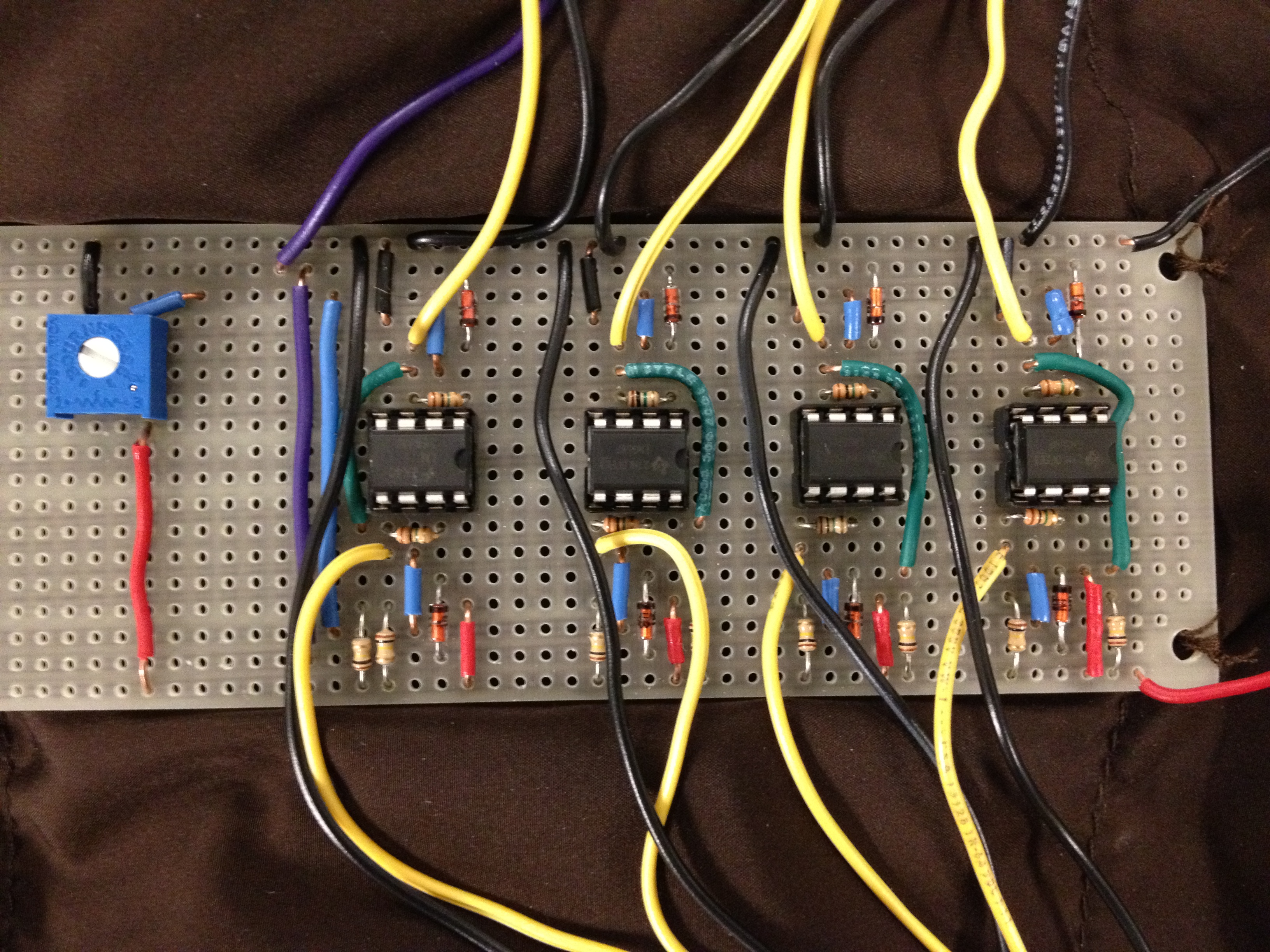
The responder unit is responsible for registering laser signals that land on a user. The vest is lined with phototransistors spaced 7.5cm apart, in order to guarantee at least one phototransistor being hit if the laser module is at least 2m away. Each phototransistor is biased as a common collector, with the collector connected to an op-amp to amplify the signal. A potentiometer is used to determine the correct biasing voltage for the op-amp. The output is then routed into a reverse-oriented diode, which forms part of the OR-gate that consolidates the signals from all the phototransistors. Our current implementation uses 8 phototransistors, although this can easily be expanded to higher numbers by repeating the sub-circuit. A schematic with two iterations of the sub-circuit. is shown below.
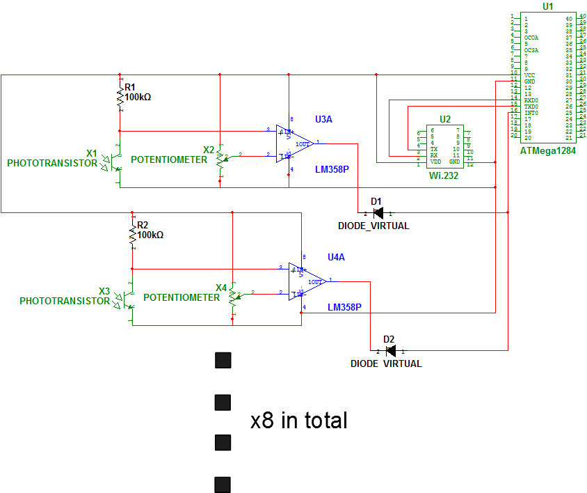
And below is a photo of the circuit itself:
Diode OR-gate
The output of the gate connects to the input pin of the microcontroller. The input pin is connected to a 5V source via a pull-up resistor, and hence defaults to 5V when it is not being driven. Since the op-amp outputs a low signal when a laser beam is incident upon the connected phototransistor, this will cause the input pin of the MCU to go low as well due to the diode being in the forward active region. Conversely, if the pin is pulled low by another Schmitt trigger while this Schmitt trigger still has a high output, the diode will now be reverse-biased and allow the voltage differential to persist. This behavior forms the basis of our simple diode-based OR-gate.
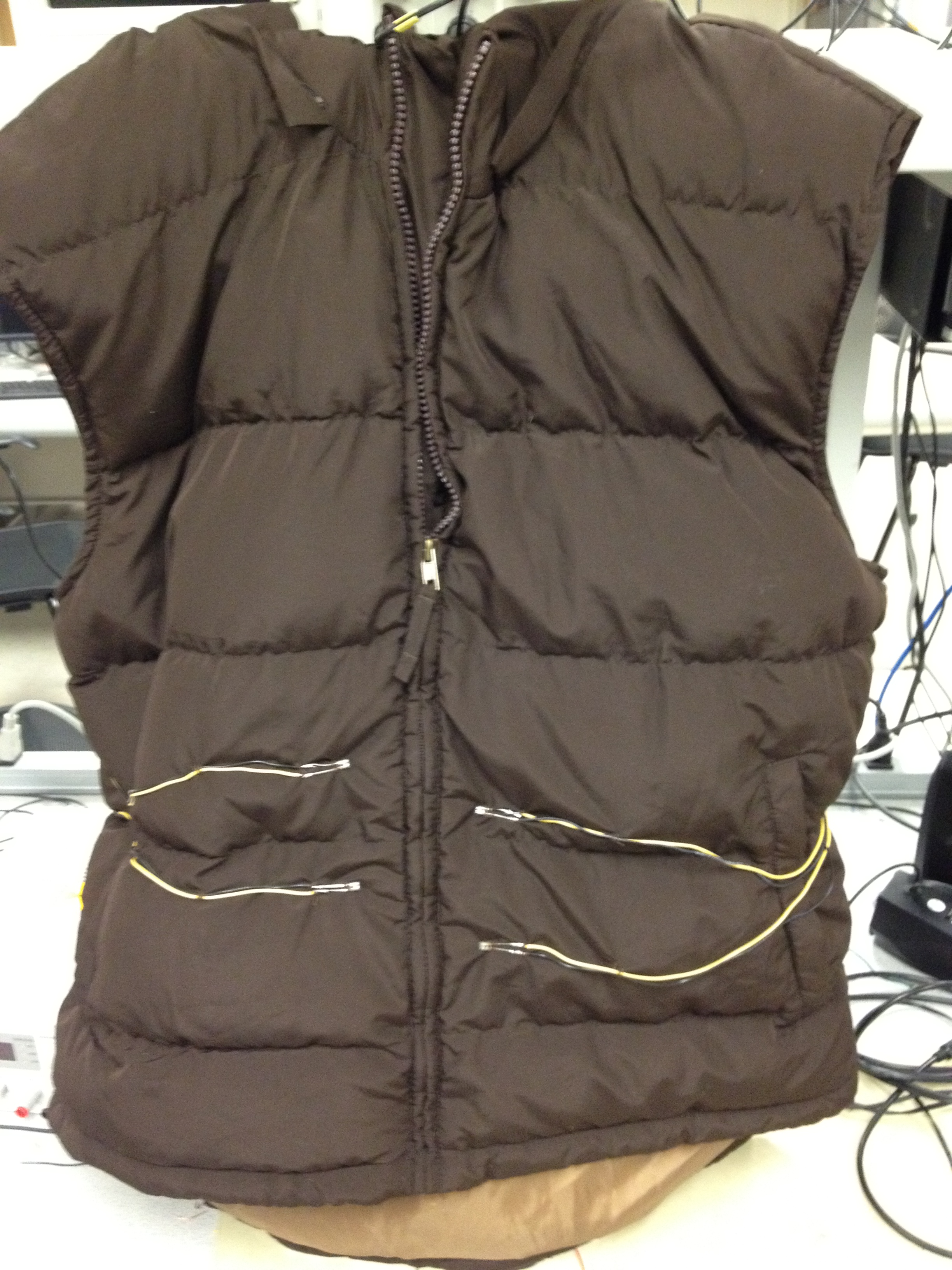
Vest Layout
Due to the limited time and number of components we have, we decided to place four sensors on the front and four sensors on the back of the vest. Each set of four forms two adjacent equilateral triangles with sides of length 7.5cm. This ensures that any laser beam of sufficient radius (larger than the circumscribed circle formed by the triangles) will be detected if the center falls within a triangle.
Plethysmograph
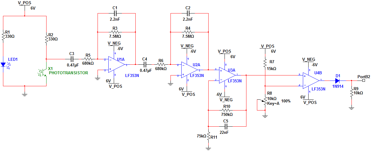
The figure above shows the pulse plethysmograph circuit used in the IFF system. It uses an infra-red emitter and an NPN phototransistor to detect a pulse. The IR emitter and the phototransistor are attached to a clip. The clip is intended to detect pulse at a finger. The circuit uses an inverting active band-pass filter and an adjustable comparator to produce a clean voltage signal that swings from -3 V to 3 V while reading a pulse.
The cut of frequencies of our filters are given by:
![]()
![]()
This pass band amplifies frequencies in the range from 0.66 Hz to 3.33 Hz, allowing us to detect a pulse. The output of the comparator circuit is input to the non-inverting input of the analog comparator in the MCU in the responder unit, with a reference voltage of 0V.
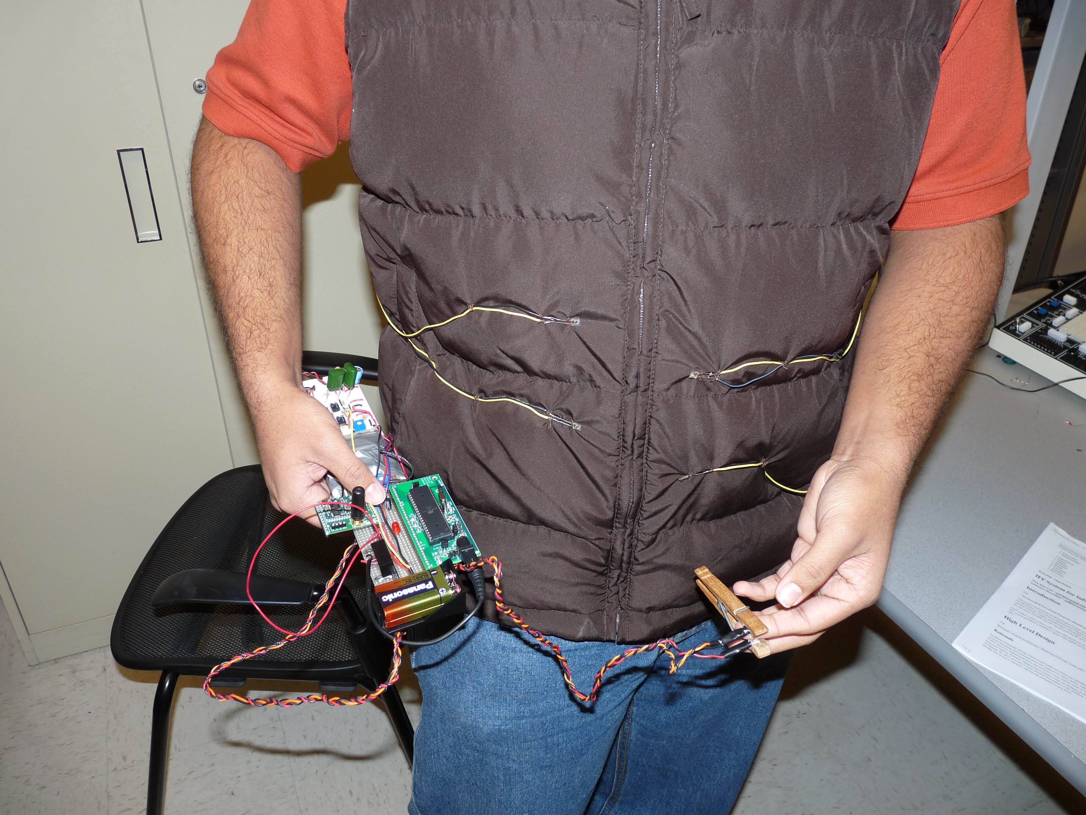
The plethysmograph is finally integrated with the other responder module components. The picture below shows the plethysmograph on the left, with the clipper going over a finger to sense a pulse. The circuit board on the right houses the MCU, and is where the plethysmograph signals and phototransistor array signals are routed; the vest with the phototransistors are connected via the three wires exiting the top of the picture.
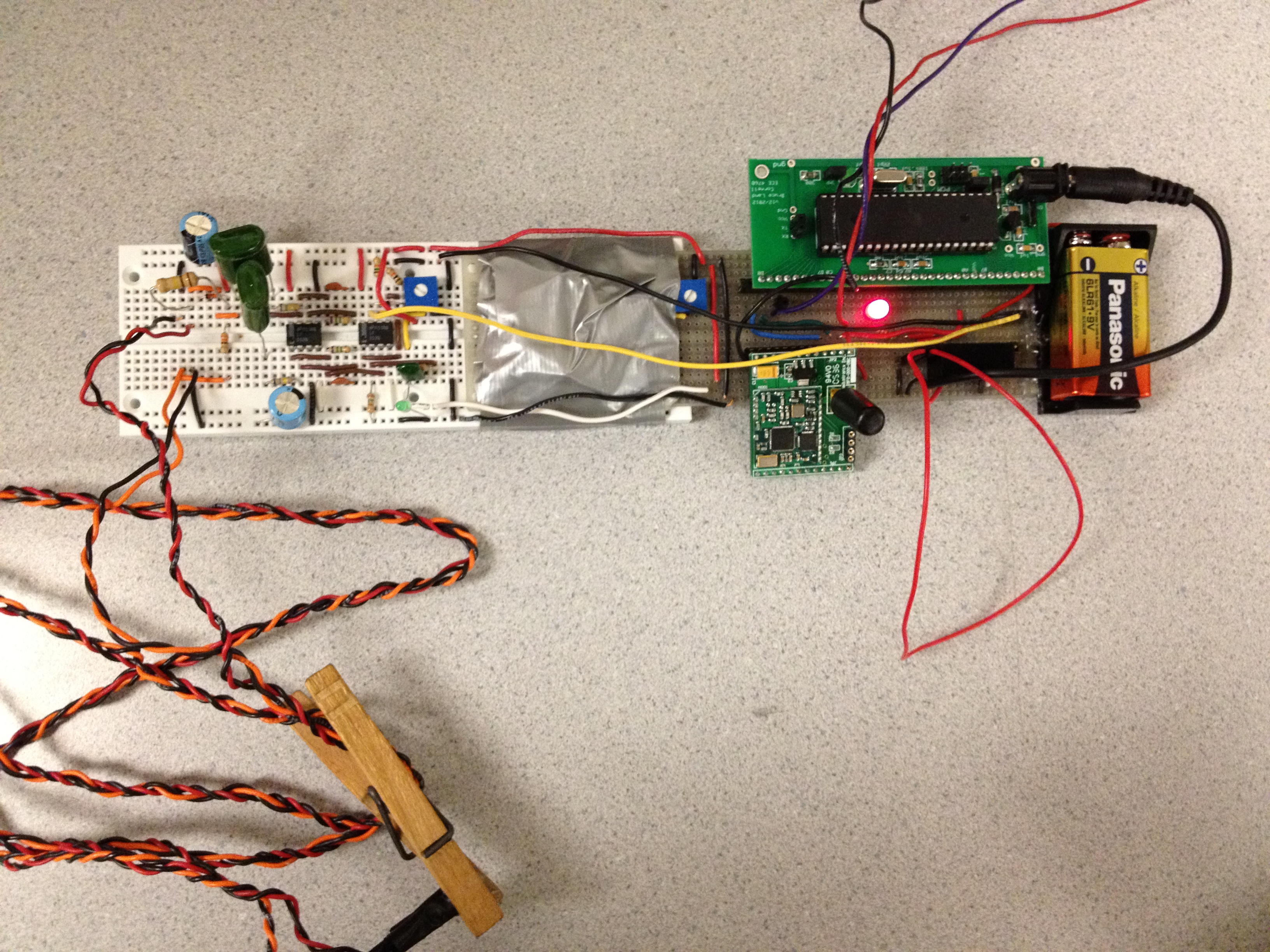
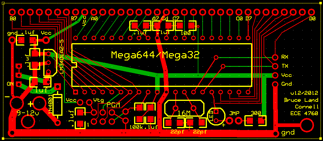
Microcontroller Target Board
We used an ATMega1284 mounted on a PCB designed for the course. The board schematic and layout were provided by Dr. Land. The board has a DIP socket for the MCU, and a LM340LAZ-5.0 regulator to convert the 9 V to 12 V input to the 5 V Vcc for the MCU.
Wireless Communication
We used FCC-approved Wi.232 radio modules, which operate in the 915 MHz ISM band with frequency shift-keying (FSK) modulation. The radio modules require no setup, and once power is applied they act as a transparent bridge for UART communications between two devices. The wire connections are shown in the responder and initiator unit schematics. One caveat is that the radio modules only support baud rates up to 2400 Bd; we had to make changes to the given UART code, because the high register UBRR0H was not set correctly for low baud rates.
Power Source
We use 9V batteries to power our MCU. We also have a 5V DC-DC converter to step down the 9V power source to a +-5V source for the op-amps in the plethysmograph circuitry.
Results
TopSpeed & Performance
The system works well, and is relatively responsive. By using the TRT OS, we can execute multiple timing-based tasks concurrently. It takes 0.5s for a hit to register, including UART and wireless transmission time. This timing can be further reduced if we reduced the time gap between iterations of tasks. It takes 1s for the laser leaving the area to be registered. This is an acceptable level of lag in detection, since it amounts to extending the no-fire time and will not lead to friendly fire scenarios.
Using the 4mW red laser, we obtained an effective range of the device for up to 10m. This range can be further increased if an infra-red laser and phototransistors were used instead, since interference from the environment would be minimized in that spectrum compared to visible light. Increasing the power of the laser is also another easy way to increase the useful range of the device. If we use a more sophisticated amplificatio stage for the phototransistor outputs and used a decoupling capacitor to remove the DC bias, we can also get much higher sensitivity in the responder unit and this will also extend the range of the system.
In terms of power consumption, the initiator unit operated at 9V and 30mA, making for a power draw of 0.27W. The responder unit, including the plethysmograph and phototransistor network, draws a heavier 80mA at 9V. This translates to a 0.72W power requirement. Both transmitting and responder units consume a modest amount of power, and can run for hours on a standard 9V battery. We estimate that the system can run for up to 7 hours on a rechargeable 9V Lithium-ion battery; this can be doubled if two batteries are connected in parallel, making it feasible for extended field usage.
Accuracy
Within the specified range of 10m, the system works as specified and produces no false negatives. However, because the same reference voltage is used for all op-amps while on the other input, bias voltages might differ across phototransistors, some phototransistors will be more sensitive compared to others. Environments with high lighting contrast may exacerbate the problem, possibly causing a false positive to occur. This situation is relatively rare, and can be remedied by using a DC-decoupling capacitor and ensuring that bias voltages have sufficient leeway in both directions.
Safety
The project does not make/use any projectile, weapon, alcohol or drugs. Though this system is designed to be used in conjunction with weapons, it will be implemented and demonstrated without any weapons. A simple cardboard tube is sufficient to simulate a rifle’s barrel.
The only safety concern for this project is its electromagnetic radiation, both in the visible and non-visible spectrum. We use a class IIIa laser with a maximum power output of 4mW, which causes damage to the eye if directly exposed for over two minutes. We consider this an unlikely scenario in the user environment, since the objective would be to point the laser away from friendly forces. Because we use a concave lens to spread the beam, the possibility of retinal damage is even lower.
Electromagnetic radiation in the 900MHz frequency spectrum is used for communication between modules. Since the radio module is FCC-certified, it conforms to all applicable safety standards for radio emissions as well.
Interference
There is a possibility of radio interference if other groups use the same radio modules and operate on the same channel. Thankfully, this has not occurred for us. If the situation arises, one can always change the radio channel by following the instructions in the datasheet.
Usability
The system is designed to be usable by all active personnel in the field. Since our hardware is intended to be mounted on existing equipment, there is no special requirement for using it. However, our sound-based alert system might pose a challenge for the hearing-impaired; the buzzer may be replaced by a small vibrating motor to provide haptic feedback instead.
Conclusion
TopSummary | Further Improvements | Intellectual Property Considerations | Patents |Ethical Considerations | Legal Considerations | Acknowledgments
Summary
It was very satisfying to implement our own ideas and see it to fruition. We met the specifications that we set, and achieved our goal. This project presents a cheap, portable system for friendly-fire detection that is easily adapted to existing equipment, allowing rapid deployments.
| Functional Specification | Implementation | Achieved? |
|---|---|---|
| Detect when friendly force is in line of fire | Laser & Phototransistor Modules | Yes |
| Sound a warning when weapon may cause possible friendly fire | Buzzer & Radio Modules | Yes |
| Permanent deactivation upon removal | Plethysmograph | Yes |
| Portable in a field setting | Compact form factor, low power | Yes |
Further Improvements
As mentioned in the earlier performance section, there are several ways we can increase the range of the system. Given more time, we would also like to increase the number of phototransistors in the responder unit to cover a larger part of the body. Lastly, we would switch to an infra-red laser once all the debugging work is done, so as to avoid detection in the visible spectrum.
Intellectual Property Considerations
Our work uses the open source TinyRealTime kernel (written by Dan Henriksson and Anton Cervin) as a task scheduler for the various software processes in the project. Our UART code is written by Joerg Wunsch (with modifications by Dr. Bruce Land and Jeff Melville) and released under an interesting "beer-ware" license. All other code is entirely original, written and maintained by us. The transponder systems currently used on fighter aircraft served as inspiration for this project.
Patents
The following patent covers work that is similar to our own:
Secure covert combat identification friend-or-foe (IFF) system for the Dismounted Soldier
Inventors: John B. Roes, Deepak Varshneya
Original Assignee: Cubic CorporationAbstract: A combat IFF system, for use in a combat exercise or on the battlefield, including a helmet-mounted passive IFF response unit and a weapon-mounted IFF interrogatory unit for each soldier. Infrared (IR) signals are employed for both challenge and response. The IR response signal is a very narrowly-targeted reflection of the relatively narrow IR transmit signal, thereby minimizing interception opportunities. The transmit and response signals are encoded in a transaction that cannot be compromised even when either or both signals are intercepted and decoded by the enemy. The combat IFF system includes biometric anti-spoofing features that prevent any use by an enemy in possession of captured units. Military radio-frequency (RF) spectrum is not required so there are no bandwidth limitations on simultaneous IFF transactions in the battlefield. A combat IFF transaction is completed in milliseconds.
Our project is independent work and belongs to except where mentioned on this page. The following patents apply to similar IFF systems :
Identification friend or foe system including short range UV shield
Inventor: Daniel A. Britton
Original Assignee: The United States of America as represented by the Secretary of the NavyAbstract: An identification friend or foe system for use by a weapon to determine whether a target that has been selected is a friendly target comprises a signal source attached to the target and arranged to radiate encrypted signals. A detection system attached to the weapon includes a receiver arranged to receive the encrypted signals when the weapon is within a predetermined range from the target. Signal processing apparatus is connected to the receiver and arranged to determine whether the encrypted signals identify the target as being friendly. The central processing unit is arranged to decrypt the encrypted signal and produce a disarm signal if the target is identified as being friendly. The central processing unit preferably is also arranged to produce a signal that causes the weapon to perform a collision avoidance maneuver to avoid colliding with the target if the target is identified as being friendly.
Laser vibrometer identification friend-or-foe (IFF) system
Inventors: John R. Wootton, Gary Waldman, Gregory L. Hobson, David Holder
Original Assignee: Electronics & Space Corp.Abstract: A friend-or-foe (IFF) identification system (10) comprises a laser generator (12) for generating and transmitting a laser beam (B). A beam splitter (16) divides the laser beam into two beams. One of the beams (B1) is directed along a reference path (P). This beam is reflected back along the path by a mirror (24) positioned at the end of the path. The other laser beam (B2) is directed at an object (T) to be identified as a friend or foe. This second beam reflects off the object and the return, reflected beam is detected. The reflected beam includes a vibration signature of the object under investigation. The return beam and reference beam are processed together to correct the vibration signature of the object for arty distortions. This allows an accurate target signature to be obtained. Next, the target signature is compared against other signatures. The results of the comparison provide the IFF identification.
Active cooperative tuned identification friend or foe (ACTIFF)
Inventors: Jacques Dubois, Sophie La Rochelle
Original Assignee: Her Majesty the Queen in right of Canada, as represented by the Minister of National DefenceAn optical identification friend-or-foe (IFF) system for vehicles comprises an active cooperative identification friend-or-foe (ACTIFF) system wherein a responder optical head is located on each friendly vehicle. That responder optical head comprises a number of small panels arranged in an array with surfaces of adjacent panels being at an angle to each other, the outer surfaces of the panels being coated with laser paint designed to emit radiation at one or more selective wavelengths when subjected to a suitable interrogation pump beam. Those selective wavelengths form an identification code for a vehicle. In operation, an interrogating vehicle would transmit a narrow well-collimated infrared (IR) beam towards a target vehicle causing laser paint on the coated surfaces to emit the selective wavelengths when subjected to that IR beam. These wavelengths can then be detected by the interrogating vehicle for identification purposes.
Ethical Considerations
The IFF system is designed to minimize friendly fire in a military scenario. Although it will be attached to weapon systems, it does not contribute in any way to the performance of the weapon. By alerting soldiers to possible friendly-fire situations, we can reduce the occurrence of injuries caused by friendly fire. As a system that safeguards human lives and reduces unnecessary risks during combat situations, we believe that it is completely ethical to develop and implement it.
The system can be used for civilian purposes too. For example, everyone in a park/forest designated for hunting could be required to wear a civilian IFF transponder, and all hunting rifles could be fitted with IFF receivers. These IFF keys could be federally regulated, and would minimize hunting accidents. In a more humorous vein, the system could even be used for laser tag.
In the process of designing and implementing this project, we adhered to the IEEE code of ethics and represented our work and our concepts as faithfully and accurately as possible. All design decisions were made with the safety of the user in mind; voltage levels are kept to the necessary minimum, and there are no high-current elements. The form is kept as compact as possible to minimize weight and volume, reducing the potential for injury through mishandling of the system.
We only used technology that we were familiar with, and have done a thorough risk assessment to ensure that the system is safe for the user and others in the vicinity.
Legal Considerations
This project is designed to comply with course regulations and FCC rules. The Wi.232 radio module is certified by the FCC and conforms to all applicable standards, including limitations on radiation power. Operating it at the 900MHz also allows us to avoid having to obtain special licenses for wireless communications.
Acknowledgments
We would like to thank all course staff for their invaluable help over the semester.
The TAs have been generous with their time, and are always ready to assist if we run into problems.
Dr. Bruce Land, the course lecturer, has been very willing to share his vast experience with us, and with endless patience is always on hand to help us out and locate the most well-hidden mistakes in our code and circuits.
Appendix
TopBudget
| Item | Part Number | Vendor | Price | Quantity | Total Price |
| ATMega1284 | Lab Stock | $5.00 | 2 | $10.00 | |
| PCB for ATMega1284 | Lab Stock | $4.00 | 2 | $8.00 | |
| White Board | Lab Stock | $6.00 | 1 | $6.00 | |
| Solder Board (6 inch) | Lab Stock | $2.50 | 3 | $7.50 | |
| 40-pin DIP Socket | Lab Stock | $0.50 | 2 | $1.00 | |
| 8-pin DIP Socket | Lab Stock | $0.50 | 4 | $2.00 | |
| SIP Sockets | Lab Stock | $0.05 | 24 | $1.20 | |
| Header Socket | Lab Stock | $0.05 | 72 | $3.60 | |
| LEDs | Lab Stock | $0.00 | 2 | $0.00 | |
| Resistors | Lab Stock | $0.00 | $0.00 | ||
| Capacitors | Lab Stock | $0.00 | $0.00 | ||
| Wires | Lab Stock | $0.00 | $0.00 | ||
| Wi.232DTS-EVM-R Radio Module | Lab Stock (donated by Dr. Bruce Land) | $0.00 | 2 | $0.00 | |
| Dual-Convex Lens | L5315 | Surplus Shed | $4.00 | 1 | $4.00 |
| 650NM Laser Module (Class IIIA) | VLM-650-03-LPA-ND | Digi-Key | $13.18 | 1 | $13.18 |
| 940NM IR Emitter (Clear, Side Look) | 160-1063-ND | Digi-Key | $0.49 | 1 | $0.49 |
| NPN IR Phototransistor (Clear, Side Look) | 160-1065-ND | Digi-Key | $0.46 | 9 | $4.14 |
| 9V Battery Holder | BH9VW-ND | Digi-Key | $1.51 | 2 | $3.02 |
| DC/DC Converter (+/-5V Out, 2W) | 102-1521-ND | Digi-Key | $13.66 | 1 | $13.66 |
| Piezo Buzzer (4kHz, 12.2mm) | 445-5229-1-ND | Digi-Key | $0.79 | 1 | $0.79 |
| Battery Alkaline 9 Volt | P647-ND | Digi-Key | $1.98 | 2 | $3.96 |
| Op-Amp IC, 700KHZ | LM358P | Digi-Key | $0.49 | 4 | $1.96 |
| Op-Amp IC, JFET 3MHZ | LF353P | Digi-Key | $0.63 | 2 | $1.26 |
| Cable Assembly, Barrel Power | CA-2185 | Digi-Key | $1.90 | 2 | $3.80 |
| Brown Vest (Old) | Aadeetya | $0.00 | 1 | $0.00 | |
| Grand Total: | $89.56 | ||||
The bill of materials above is sufficient for one initiator and one responder unit.
Circuit Schematics
Code Files
Main Code File (main.c)
TRT Kernel (trtkernel_1284.c, trtSettings.h)
TRT UART (trtUart.c, trtUart.h)
Work Breakdown
| Aadeetya | Wen Hao |
|---|---|
| Hardware procurement | Getting radio modules to work |
| Plethysmograph construction and coding | Constructing laser & phototransistor modules |
| Development board and circuit board construction | Code for laser pattern recognition and laser output |
| Communication protocol between modules |