Melissa Hamada (msh276), Jeff Heidel (jeh295), Hanna Lin (hl577)
A low-cost, hand-made laser projection system.
Introduction
For our ECE 4760 final project, we designed a low-budget laser projector system. The project was broken into main sections: the custom hardware designed and fabricated to make up the projector, the circuitry controlling the hardware, and the custom software controlling the circuitry.
We also chose this project due to our interest in optics involving lasers as well as practicing motor control. Various processes for building laser projectors have been documented and are available online. However, there have not been many publications on low-budget laser projectors that do not use an audio speaker as a source. This inspired us to implement our own low-cost laser projector using a relatively low end microprocessor.
High Level Design
Rationale and Sources
Laser projectors are devices that project manipulated laser beams onto a screen for a multitude of reasons such as for entertainment, professional, and research purposes. These projectors generally consist of similar components: lasers, mirrors, actuators, and other optical components housed in an enclosure. Several high-end projectors are custom built and have several functions that allow for different laser effects. Of these, the most simple is the X-Y scanner, which can be used for the most generic effects, particularly for projecting images onto a screen. It is this X-Y scanner that we have chosen to implement in our laser projector.
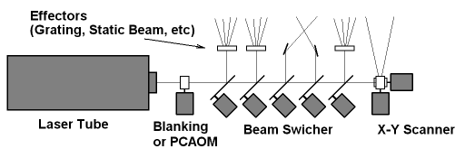
The general setup of a laser projection system can be seen to the right, taken from this site. The X-Y scanner that we use in our system can be at the farthest right. The beam switcher to the left of the scanner is a mechanism that feed the laser beam into different optical effectors. To the left of that is the blanking mechanism that interrupts any unnecessary laser beams, but this can be left out if the laser has TTL (transistor-transistor logic) modulation, which allows the user to selectively turn the laser on and off to avoid unwanted lines in the projected image as the laser traverses the screen. To the farthest left is the laser itself. A simplified view of the X-Y scanner can also be seen on the right, below the general setup and is from this site. The scanner consists of two galvanometers with mirrors attached at the end of the rotors, arranged so that the mirrors are orthogonal. The laser beam is deflected by the x-axis galvanometer mirror and is then deflected again by the y-axis galvanometer to the projection screen. The combination of deflection angles of both mirrors determines the beam direction.
Most commercially available and professional laser projectors are costly and are not easily duplicated. These high-end projection systems tend to use galvanometers as the mirror actuators, but these can be some of the most costly parts in the system. On the other hand, there are several published methods available for making a laser projection system for much less by replacing the galvanometers with other components that can do a similar job, though the quality of the projection is debatable with these other methods. One example is to replace the galvanometers with motors such as in this example by Instructables user Mtaram where DC motors are used to manipulate the mirrors. Another is to use audio speaker woofers and attach the mirrors to the speaker cones as in this example by NothingLabs. This project by Alan Turner also uses audio speakers, though in Mr. Turner's system, the laser projection was based off of music playing through the speakers to which the mirrors were attached, rather than manipulating the speakers .
For our project, we chose to closely follow the work on laser projectors done by ChaN, and ChaN's documentation can be found here. ChaN's design is a low-cost laser projector, but instead of replacing the galvanometer with a different component, he chose to fabricate his own and included a position-feedback sensor in order to make the galvos closed-loop and therefore be able to better control the laser positioning.
Logical Structure
The project can be broken down into three distinct sub-sections. The first encompasses the mechanical hardware that makes up the laser projector, shown in the figure in the Rationale and Sources section, which shows the general laser projector hardware, minus the blanking and switching mechanisms. The second is the electrical hardware that provides the power to the galvanometers and microcontroller, takes in the signal from the position detector sensor, and also provides the control loop in order to allow for PD control of the galvanometers. The third is the software used in order to take the image to be projected and send the appropriate signals to the galvanometers to accurately manipulate the laser beam.
Mechanical
For this project, the main challenge was designing and fabricating the magnet-rotor combination, which to which both the position detector circuit and mirrors are attached. Another challenge was the galvo enclosures that house the hand-wound coils and magnet-rotor assembly. The coils used in this project were also wound using custom hardware that allowed us to wind coils that are rectangular in the center to optimize the space in which the magnets rested between and within the coils. Finally, each of the printed circuit boards for the electrical side were also made by in-house.
Electrical
There were several custom electrical systems that were designed and fabricated for the projector. First is the system that regulates the voltage for the system. Next is the DAC for outputting the desired position of the laser beam. Finally, there is the PD control of the galvanometers, implemented in hardware.
Software
The software is divided into low level microcontroller code and high level code that runs on a Linux PC. The low level code handles serial input and controls the DAC as well as the laser modulation. The high level code handles file parsing, point scanning, frame display, and serial transmission to the control board.
Hardware/Software Tradeoffs
The main tradeoff between hardware and software was the decision of where to implement the control loop for the galvanometers. For this project, we decided to implement the control loop in hardware. This is primarily due to the infeasibility of implementing the control loop in software. In order to achieve a scan rate of 20k points per second, we would need to do a full motor position set in about 50 microseconds. This means we would need to take a number of analog samples of motor position using an ADC. However, even with the most expensive ADCs available, we would still only get several samples per point which would not be sufficient to do successful PID / PD control. As such, we implemented a PD control loop using op-amps.
Standards
For the laser projector, there are a few standards that apply. First are the safety standards Z136.1 from the American National Standards Institute (ANSI) and 21CFR subchapter parts 1040.10 and 1040.11 from the Federal Laser Product Performance Standard (FLPPS), which assigns lasers a classification depending on the potential for causing biological damage. The laser used in this projector is classified as a class 2 laser. This classification means that this laser is safe for unintended exposure, but prolonged staring should be avoided. The maximum permissible exposure(MPE) is 0.25 seconds, and there is no hazard area when based on unintended exposure.
For communication between the microcontroller and the Linux PC, we use the RS-232 communication standard. For communication between the microcontroller and the and the DAC, we use the serial peripheral interface (SPI). Laser files used in this project conform to the ILDA (International Laser Display Association)'s file format. This file format describes a series of points that can be used to draw a laser image. This file format is widely used in commercial laser applications and as such, there are plenty of ILDA format images available for use. Additionally, the use of this format makes our laser projector compatible with existing systems.
Intellectual Property
Currently, there are several patents that involve laser projection systems. Some patents focus on the safety or projection head aspect of the system. Other patents such as the one by Tsuida(US 8519324 B2) or Rueb, Jackson, and Morden (US EP1719580 B1) describe novel laser projection systems. These patents are sufficiently different from our project. When designing our system we did not search for existing patents to base our design off of. Our design was based off of the open laser projector project by ChaN and off of concepts in electrical, mechanical, and software engineering that we have learned throughout our academic careers, as well as the basic knowledge of laser projection systems we came across while doing preliminary research.
Program/Hardware Design
One challenging aspect of this project was the division of tasks between hardware, low level software, and high level software. The software must be able to scan laser points at up to 20,000 points per second and scan a wide range of frames.
We quickly discovered that storing frames in memory would quite a good deal of RAM. A typical laser frame contains around 800 points. Since our DAC has 12 bits of resolution and we need to store 2 points, we need a total of 3 bytes for the point information. Finally, since we need a blanking bit for the laser itself, we need an additional byte meaning each point requires 4 bytes of memory. As such, each frame requires 3.2kB of memory.
Given that the highest-capacity Atmega microcontroller that we could feasibly implement has around 8 kB of flash memory (enough to store only 2 frames) we decided that we would need to either come up with a solution that used an external memory such as a SRAM module or an SD card, or we would need to stream the frame data. To minimize hardware complexity and maximize our display capability, we chose to stream data directly to the microcontroller over serial. In terms of microcontroller choice, we picked the ATmega 328P due to its low cost and our familiarity with its features.
This approach entails low level microcontroller software that reads from serial at high speeds and updates the DAC / laser blanking and high level software on the computer that provides points at the appropriate rate, as we will outline in the following sections.
Microcontroller Software
The microcontroller is responsible for controlling the motor control board as well as driving the TTL line for the laser.
Each motor control board takes in a voltage which is used as a set point. In order to output two voltages the microcontroller must drive a DAC.
We use the TI TLV5638 12-bit dual-channel DAC to achieve this. The microcontroller communicates with this DAC using the SPI protocol.
This DAC was selected based on its quick set time as well as its ability to update at the desired frequency.
Care was taken to ensure that the SPI communication happens as quickly as possible in order to ensure the highest possible scanning rate.
As such, we set the clock rate to fck / 2 with CPHA=1 to match the TLV5638. SPI commands were verified on an oscilliscope.
Given our operating frequency of 16 MHz, our SPI clock rate of fck / 2, each byte requires 1 microsecond to send, meaning that each point will require 4 microseconds (recall 4 bytes per point). As a result, we can achieve a maximum scanning rate (SPI limited) at 250k points per second.
The TLV5638 proved more challenging than expected to integrate. For an unknown reason, we discovered that in order to write to channel B, the DAC requires that all commands be sent twice.
When only sending commands once (as indicated in the datasheet) examples, the DAC would not properly output the value of channel B.
Fortunately, the DAC SPI is not the rate-limiting factor of the microcontroller, even when the SPI overhead is doubled. Our maximum rate is still around 125k points per second.
The microcontroller must also control the laser blanking in order to turn on the laser beam when a line should be drawn in the scan path.
In order to accomplish this, the microcontroller simply uses a pin to control the TTL laser module directly.
The laser module we used is capable of 50khz modulation which exceeds the requirements of 20,000 points per second.
The final component of the control board is its interface with the computer. We chose to use an FDTI chip due to its low cost, acceptable speed, and ease of implementation. Our project uses an FDTI FT232BL on a custom board. In order to achieve the maximum point scanning speed, we run the chip at its maximum RS232 rate of 1 Megabaud (1,000,000 symbols per second). By using a baud rate calculator in combination with the microcontroller's datasheet, we determined that setting UBRR to 0 will achieve the desired rate.
Given out baud rate of 1 MBaud,our 4 byte per point requirement, and the setting of 1 stop bit, we determined that we can achieve an ideal rate of about 27,778 points per second. In practice, we found that we were able to reliably achieve 25,000 points per second before being bottlenecked by the baud rate.
Each 4 byte point has the following structure:
Byte 1
x x x M A A A A
Byte 2
A A A A A A A A
Byte 3
x x x x B B B B
Byte 4
B B B B B B B B
Where x represents "don't care", M represents the laser blanking bit (1 indicates blanked, 0 indicates the laser should be powerwed), A represents the 12 bits for the DAC's A channel (x axis) in big-endian order, and B represents the 12 bits for the DAC's B channel (y axis) also in big-endian order. There are quite a few unused bits in this byte scheme as a result of the requirement to round up to the nearest byte. Future implementations may decide to restructure this protocol to software-level implement some error correction. We occasionally noticed errors in the UART transmission resulting in dropped bytes. By restructuring the packet format such that the MSB of byte 1 is always 1 and the MSB of bytes 2-4 is always 0, we could effectively detect the first byte of any point and recover from any number of dropped bytes.
The control board software is designed to be as light weight as possible to maximize the possible scan rate. As such, the embedded code is quite trivial. The microcontroller operates in a single loop, reading data from the FDTI link and writing the data to the DAC. As such, we explicitly refrained from doing any significant processing onboard the microcontroller since most tasks could be offloaded to the high level software. Additionally, the embedded code makes use of inline directives and compiles with -O3 in order to maximize potential run speed. In order to further increase speed we considered moving to assembly, however given that we could achieve a scanning rate that exceeded our target, we decided not to.
High-Level Software
High level software displaying a dolphin animation. A ILDA laser projection file contains a series of frames. Each frame contains a series of points which are drawn as lines (with some of them blanked, drawn in red).
The high level software is in charge of parsing ILDA files and sending them to the laser projector over serial.
ILDA files are standardized laser projection files that contain a series of 16 bit points and blanking information (as well as color information in some cases for RGB projectors).
For our project we found a number of publicly available files to use for testing. We also created several ILDA format files using freeware available from this forum. All of these ILDA files are available in the datafiles directory within our repository.
Our high level code is contained within the root level directory of our repository as well as the clib and pylib folders: https://github.com/jheidel/ece4760-lab5. This software is designed to be run in a Linux environment.
We use a number of freely available open-source libraries in our high level code. We use ctypes in order to interface python code with C code. We chose to split our project in this fashion because we wanted our low level code to run quickly; however, we also wanted the flexibility of python for designing the graphical user interface. We use Glade, cairo and Gtk+3 for the graphical user interface. We also, of course, use Python 2.7 as well as a number of its included libraries, such as argparse, its threading libraries, and its logging libraries.
In order to parse ILDA format files, we implemented a file parser in C using the ILDA file format guide as reference (referenced here). Python uses ctypes calls in order to parse the file lazily to avoid a startup delay. The files are cached in memory to avoid redundant lookup in the case of animations (which are looped).
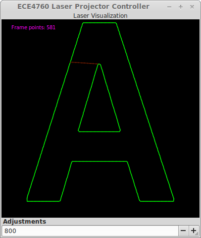
ILDA files are visualized using a GUI which displays the laser points and connects them with green lines. Blanking lines are also in red (motor movement when the laser in not turned on). If the ILDA file contains a sequence of frames (an animation) the animation is displayed at a fixed frame rate.
The python code handles the conversion of the points from the 16 bit ILDA file format to our 12 bit DAC output. Additionally, we compensate for the projection angle at this stage. Given that our DAC output corresponds to an angular set-point and our desired coordinates are projected, we must take the arcsin of our projected points in order to achieve the correct mapping to angles. Given that our input is 16 bit signed and our dac output is 12 bit unsigned, we use the following formula for the conversion:
where ILDA is our input point from our data file and DAC set-point for the motor position.
Finally, a multithreaded buffer system is implemented in C so that the python code can copy frame data to the output buffer and enable output which is then scanned at a fixed "points per second" (adjustable from the python interface). This is what carries out the actual serial communication with the microcontroller and actually scans through the points. This component is written in C to ensure that the scanning rate is as accurate as possible. We discovered that using sleep actually resulted in significant missed deadlines due to the operating system's scheduling scheme. As such, we utilize busy waiting to achieve better performance and fewer missed deadlines. In order to prevent this from happening, we would have to choose a linux kernel with a real-time scheduler.
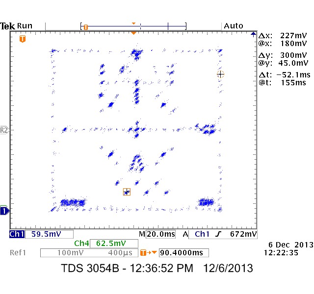
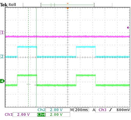
We tested this scanning system on a test frame (see in the picture to the right).
In this test, the buffer is scanned at 12,000 points per second. Given the 322 points and the 26.8 millisecond scan period, we see that the laser projector is indeed scanning at the desired points per second.
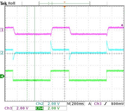
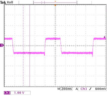
We also conducted some tests with an oscilliscope in X-Y mode in order to see the scanned output. Some of these images are included below. These tests were conducted with the angular compensation turned off to avoid distorting the images. These tests confirm that the software scans the images appropriately.
Mechanical Hardware
As mentioned above, the mechanical hardware for the system consists of the magnet/rotor assembly, galvanometer enclosures, projector tray, coil winding apparatus, and PCB fabrication. Much of the mechanical hardware followed ChaN's design, though with our own added modifications. In order to fabricate all of these components, the following hardware was used:
In order to design and fabricate the magnet/rotor assembly, we first looked to how ChaN had created his own. In his design, hard drive magnets were cut to size, epoxied to a shaft, and then ground down to size. Although this would have allowed us to save on our budget by salvaging magnets from trashed hard drives, this was not the design we chose to go with due to a few difficulties we had in fabricating and testing the design. A completed prototype rotor can be seen to the right. The first gripe was that hard drive magnets are c-shaped, which meant that they had to be ground down to a rectangular shape first. This would not have been a problem if neodymium magnets weren't so brittle (they shattered extremely easily) and would catch on fire at 150 C. Both of these characteristics made altering these magnets a pain. A second difficulty we encountered was that occasionally, the epoxy used to hold the magnets to the rotor shaft was not enough to keep the magnets in place while the assembly was being ground to a cylinder. A final complaint we had with this method was that grinding the magnets down to a symmetrical cylinder sometimes left much less magnet than we would have liked on the rotor.
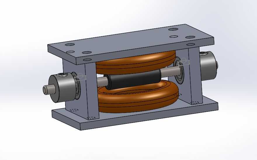
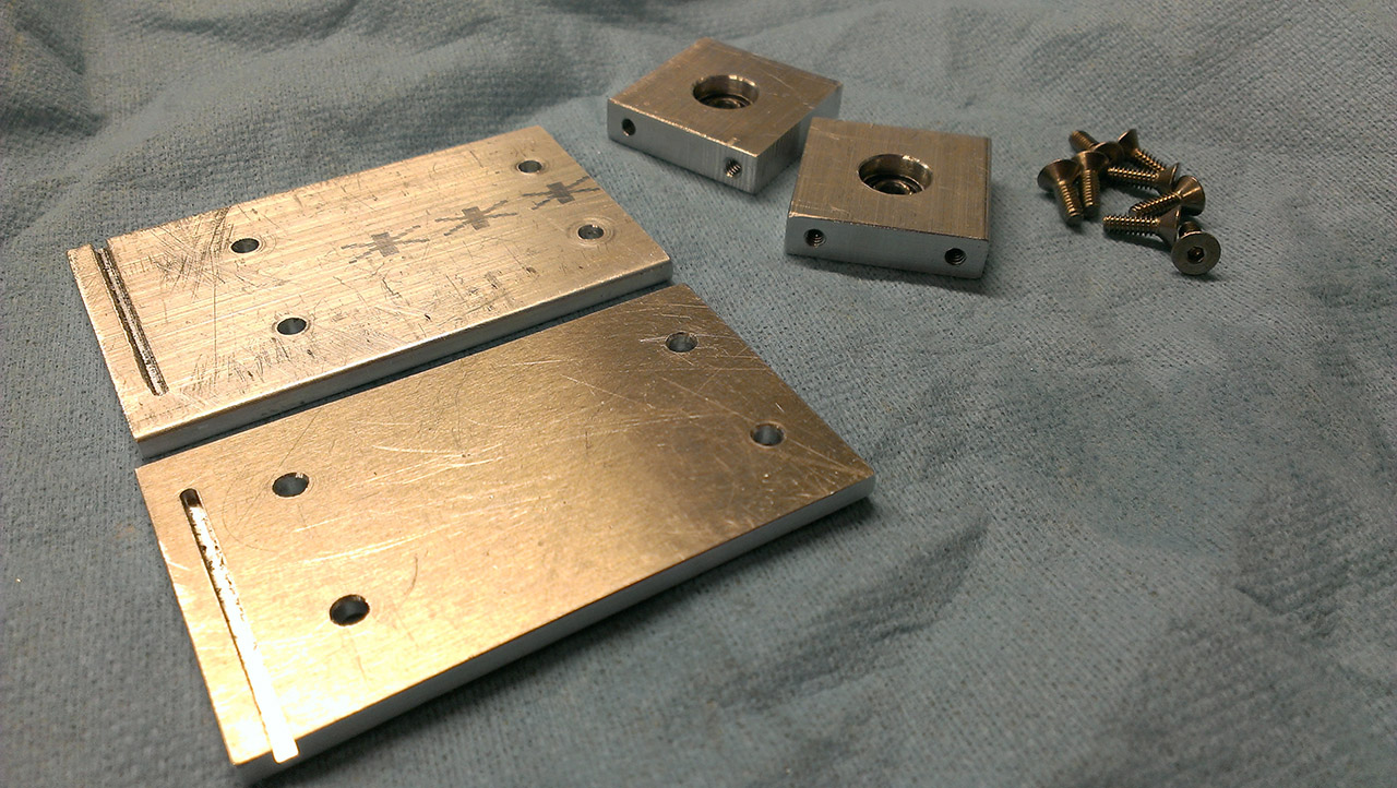
Based on the complications we ran into, we decided to instead invest in a pair of diametrically magnetized cylindrical neodymium magnets (1/4" diameter, 1" long), one for each rotor. This allowed for us to not have to worry about keeping the rotors balanced or having to grind down fragile magnets. In order to attach the magnets to the shaft, custom steel caps were designed and fabricated. The design can be seen in the figure to the right. The magnet is epoxied into one end of the cap, and the cut shaft is pressed into the other end. Two of these caps were machined for each for magnet, and the two steel caps cover the magnet completely while maintaining the magnetization. The cap was designed so that the bearings that suspend the shaft are pressed to the ends of the cap and are spaced exactly the distance used in the galvanometer enclosure. Once the rotors were pressed onto the bearings and assembled in the enclosure, the mirror and position detector electrode were attached to the ends using epoxy. both the cut mirror and electrode were attached to a shaft collar using epoxy and then adjusted on the shaft.
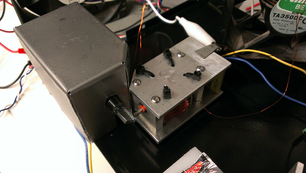
Galvanometer Enclosures
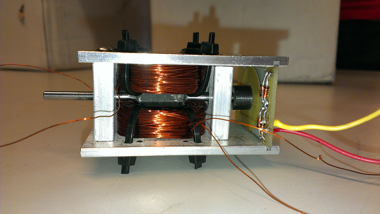
We also based the galvanometer enclosures off of ChaN's design, though the main differences are that the enclosures were machined entirely out of aluminum, the bearing blocks are square (for easier position detector board fabrication), and we also altered the mechanism for grounding the motor shafts. The enclosures house the magnet/rotor combination, bearings, position detector circuit boards (electrode and detector), and the hand-wound coils. The fully assembled galvo can be seen to the right, though with the prototype rotors and with the position detector circuit in place. Two enclosures were fabricated, one for each axis of the scanner (X and Y).
The general dimensions were based around the parts we were able to order and also around trying to optimize the amount of magnet wire we could fit into the enclosure without hindering the rotors turning, taking into account the fact that two coils would be used in the enclosures in order to surround the magnet. The inner surfaces of the bearing blocks were carved out with an endmill in order to allow for coils that were slightly larger than the rectangular space between the blocks. The top and bottom plates of the enclosure have holes to hold the bearing blocks in place and to fasten the coils to the top and bottom of the enclosure. The plates also have mirrored slots cut towards one end of the plates in order to hold the position detector board in place and perpendicular to the assembly. In order to ground the shaft, a piece of aluminum was epoxied to the outside of the enclosure. The aluminum piece comes to a point, which is centered on the shaft, and was designed as a non-rotating part to ground the rotor. The point of the electrode and the end of the shaft where it contacts were coated with conductive grease in order to ensure a good connection.
Projector Tray
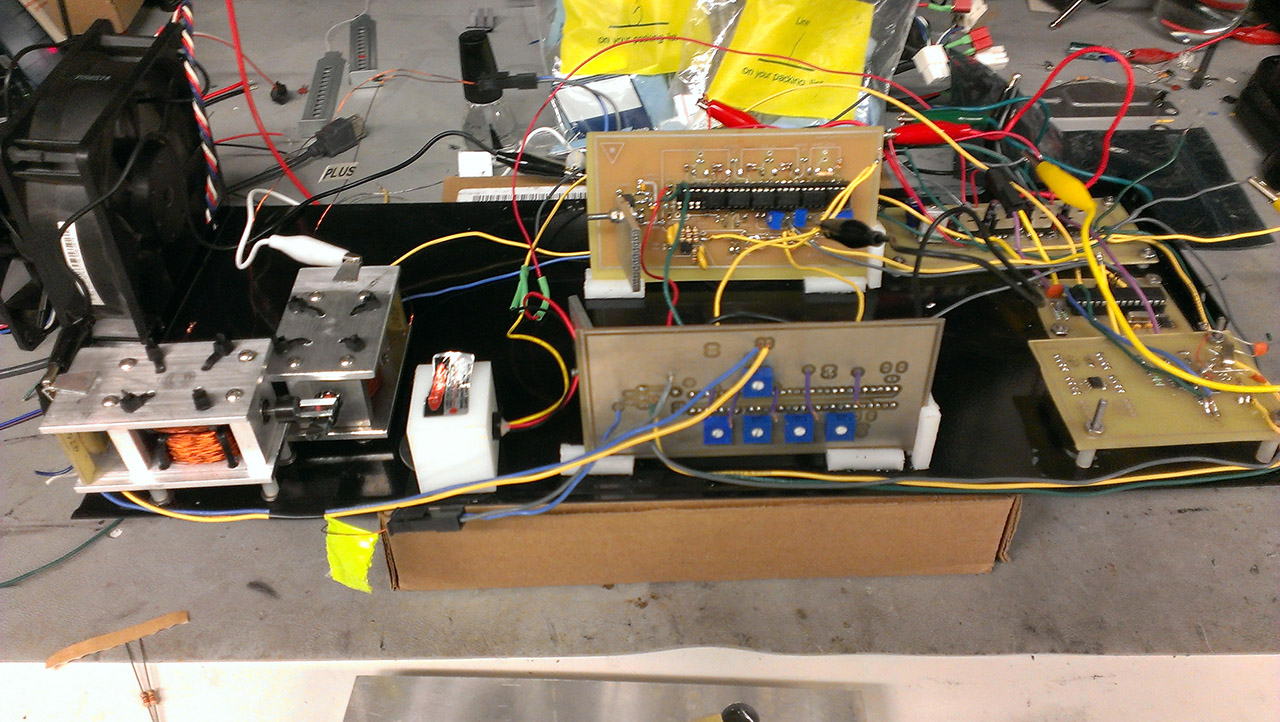
All of the hardware for the projector is mounted to a single metal tray. The salvaged tray can be seen to the right with all mechanical and electrical hardware attached. Having all components mounted to the tray allows for portability and more stability in that solid connections between wires can be made without being stressed. General standoffs were used for most boards and components, but the motor controller boards had potentiometers on both sides of the boards which required access to both sides. In order to accommodate this, custom brackets were made in order to hold the boards perpendicular to the plane of the tray for easy access to both sides.
Coil-Winding Apparatus
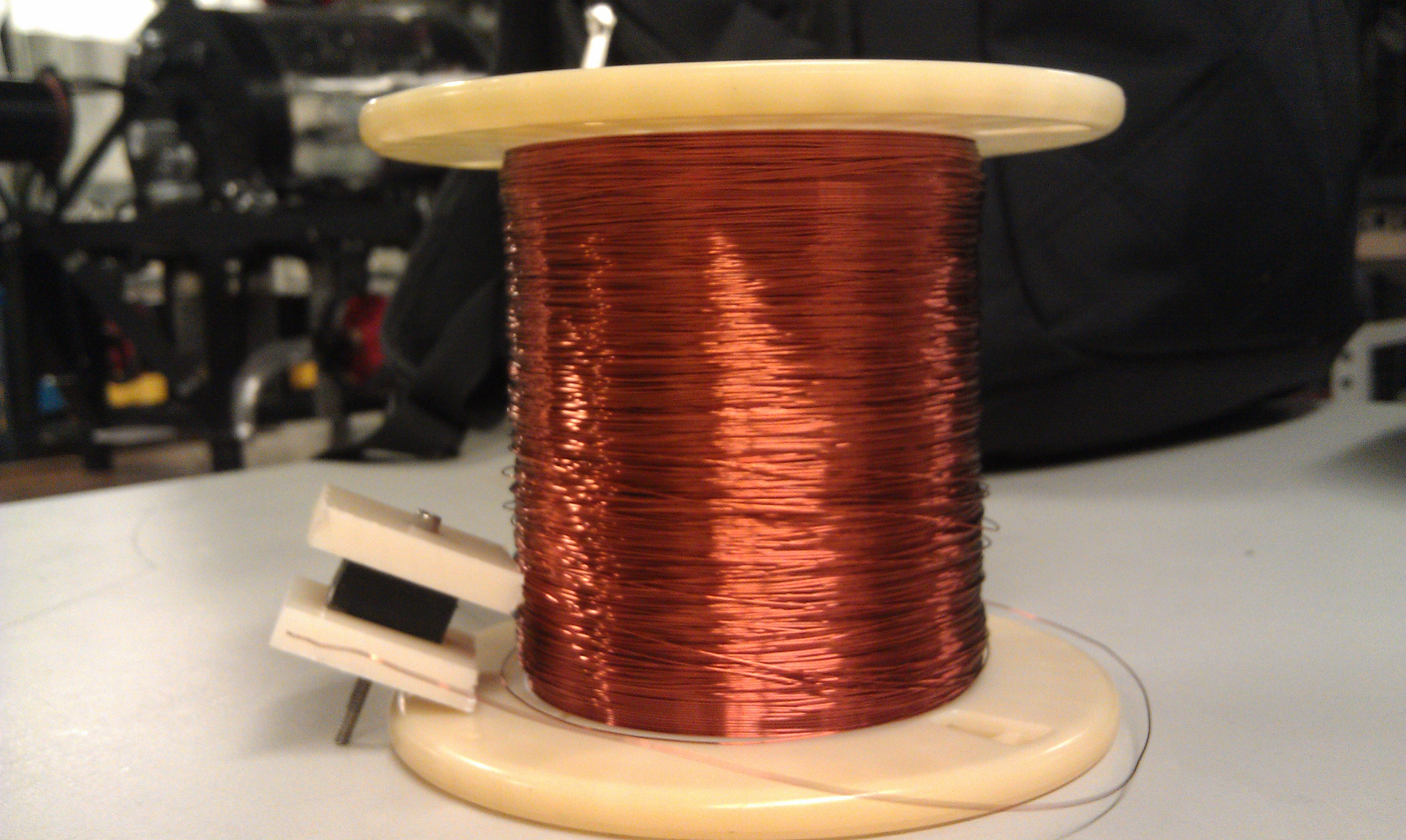
In order to wind the coils into an optimal shape for fitting into the galvanometer enclosures, a custom apparatus was made. An image of the apparatus can be seen to the right. The outer (white) pieces of plastic were cut to the size of the space within the enclosure while the inner (black) piece was cut to the size of the magnet on the rotor. The reason for this was so that the magnet would be contained within the two coils as much as possible. The three pieces of plastic were drilled through and fastened together with a bolt and nut for easy disassembly. The coils were then wound around the center piece until the outer edges of the white plastic were reached. The apparatus was then disassembled and the coil removed for mounting to the enclosure plates. We found that the coils contained roughly 350 windings each. When the galvos were assembled, it was noticed that the steel caps of the magnets would come into contact with the coils. Each coil was then compressed using a 1/2" diameter steel cylinder in order to reduce the height of the coils beneath the rotor.
PCB Fabrication
For this project, we chose to fabricate our own PCBs. This allowed us to create complex circuits using surface mount components very rapidly while also staying under budget. In fact, this method costs less in parts than a conventional "breadboard-style" solder board. Furthermore, PCB fabrication is fun and a great thing to learn. This was the first project in which Jeff attempted to make double-sided PCBs.
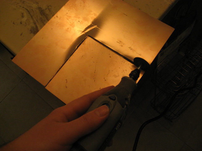
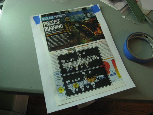
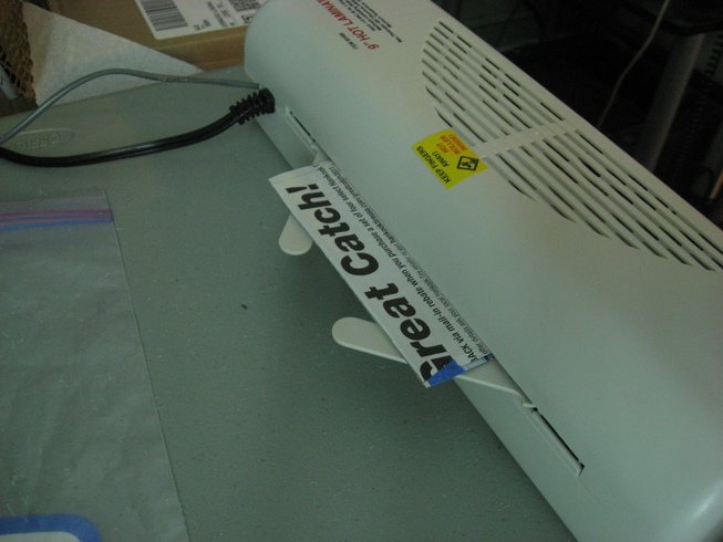
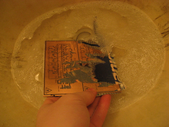
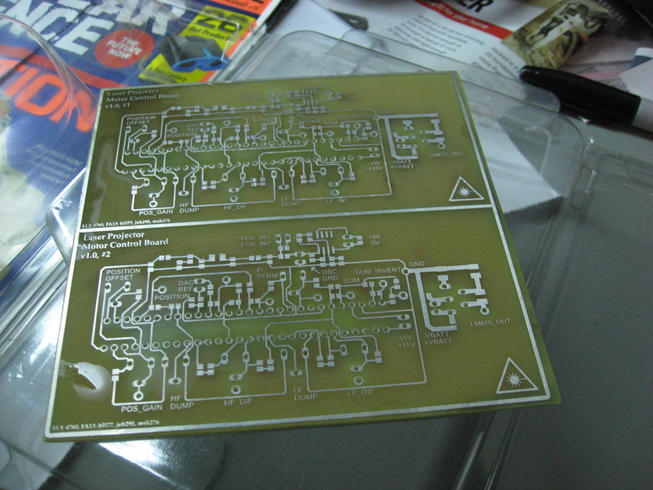
In order to fabricate all of the circuit boards used in the project, copper clad board was first purchased. The design for each board was then made using Eagle software. The design was then printed using a laser printer onto a sheet of glossy (magazine) paper. "Cheap" glossy paper is essential so that it will dissolve properly. Additionally, care must be taken to ensure the proper DPI settings and page orientations are met so the transfer will be appropriately scaled. The copper clad board is then cut to size, scored using a 3M scratch pad, and cleaned with acetone to remove any oxidation. Next, paper was pressed and heated using a laminator onto the copper clad board. For this project, we are using an extremely cheap Harbor Freight laminator that has been modified in order to slow it down to an appropriate speed. Lamination takes around 10-15 minutes for a quality transfer, depending on the board size. This effectively bonds the toner to the copper. The paper was then dissolved from the copper clad using warm water leaving the toner deposited on the copper board. The copper clad was then dried and etched in a ferric chloride solution until the excess copper came off (approximately 15 minutes). Next, the boards are drilled using a drill press and carbide drill bits. The toner is then removed using acetone and the board is immersed in a tinning solution to prevent oxidation. The boards were then ready for populating. Some images from this process are below.
Safety must be observed when etching boards as this process involves power tools and dangerous chemicals. Gloves, chemical splash goggles, and respiratory equipment should be worn when appropriate. This page does not serve to teach DIY PCB fabrication in detail. If you would like to take on DIY PCB fabrication, we recommend that you seek an existing tutorial, such as this one.
Electrical Hardware
Galvanometers
A galvanometer is an ammeter, or a device that detects electric current. It is an analog electromechanical actuator that produces a rotary detection in response to current flowing through its coil in a magnetic field. Typical galvos have a pivoting coil of wire in the field of a permanent magnet. When current flows through the coil, the coil generates a magnetic field, which acts against the magnet, causing the coil to turn and push against a spring which moves an indicator that shows the current. The design of the galvos is slightly different for this project.
For this laser projector, the moving and still parts of the galvo are switched around. As in ChaN's design, the coils are kept stationary within an enclosure, surrounding the magnet mounted on the shaft. The current running through the coils causes the rotary motion of the magnet, and subsequently, both the position detector electrode and the mirror attached to the ends. This design's functionality is close to that of a servo motor as well. In order to minimize the inertia of the rotor, the rotor was made as thin and light as possible while being symmetrical.
Closed-Loop Feedback Control
The system implements closed-loop control of the motors to stabilize the step response. Therefore there are two main parts to the motor controller: the position detector and the PD, proportional-derivative, feedback loop. Much like a servo, the motors are set with absolute position information, where two electrodes allow for 90 degrees of precision. The second portion is the PD feedback loop which uses the error in position to stabilize the output and improve the step response of the system.
Due to symmetry, it is able to detect precise positions within 90 degrees.
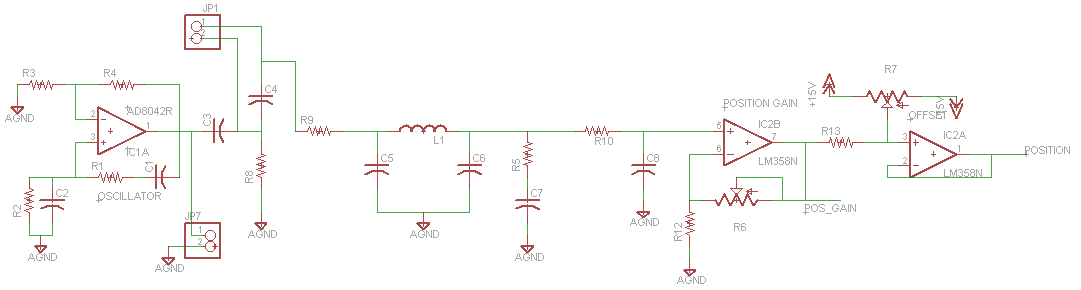
Position Detector Circuit
The position detector is used for absolute position information. However based on the scope of the project, we only needed to drive the motors within a 90 degree deflection range. We explored a few options, the potentiometer would cause undesired friction on the shaft, magnetic rotary encoders would create noise and would be highly susceptible to rapidly changing magnetic fields caused by the motors and as we did not need that great of a range, many devices were ruled out. Therefore, we decided to use a capacitive position detector. The detector uses two electrodes: one is moving and mounted to a shaft collar, the pads are grounded to provide the capacitance with the stationary electrode. The stationary electrode is arranged in 4 quadrants for 90 degrees position detection without aliasing. An 8MHz sine wave is applied to the pads with diodes rectifying the signal with positive diagonally arranged and negative region of the signal on the opposite diagonal.
When held in a specific position, the electric field will point toward the grounded electrode in the positive region and away in the negative portion. As the shaft rotates, this electric field changes in strength and direction inducing a current across a resistor thereby causing a potential. This voltage drop across the resistor corresponding to a specific position of the shaft corresponds to its specific position. The oscillating signal is important as a DC signal would simply charge the capacitor when the electrode is stationary and would thereby cause the position to spike randomly.
The signal from the position detector was then passed through a pi filter for noise, and a gain stage to get the output signal on the range of 1V pk-to-pk. We found that a gain higher than 10 would cause the signal to become unstable. Therefore, we were able to remove the potentiometer R6 for the second revision of the board. Then the signal was passed through an offset stage to adjust the DC offset in order to center the position signal. If the position signal was not centered correctly, the motor would become unstable and easily switch quadrants.
While not used in the final demonstration, a sine wave oscillator was built for the position detector. Arranged in a wien bridge, we were able to get the oscillations up to 5MHz with 2V peak-to-peak. As the frequency was on the correct order of magnitude, we found that this oscillator would have been sufficient, what was more important than the frequency is the amplitude, the higher the amplitude of the signal, the stronger the signal on the output. One important thing to note is the frequency response of surface mount versus through hole components. We found pretty early on that surface mount resistors could not handle the MHz oscillations we were trying to achieve and would produce no oscillations. Therefore we switched to through hole components on the position detector circuit.
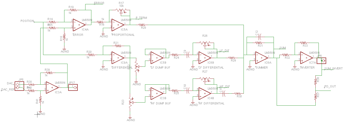
PD Feedback Control Circuit
In general with PID control, the controller calculates the error between the desired and actual position. Then, it uses those to calculate the proportional, integral, and derivative (PID) values which are the constant parameters to see how the signal changes over time in order to better adjust and predict the error of the signal. The weighted sum of the three parameters are used to adjust the actual output to the desired output and reduce the error.
One of our main concerns when designing the project was, how to achieve the best step response time. In order to achieve this, the motor would need a good gain term, however due to the Gibbs phenomenon, a very short rise time would also cause oscillations on the output. Therefore a PD controller was used to tune the output and reduce the error caused by these oscillations. Note that the integral term was removed from the controller, as discovered in previous labs, the integral term would cause additional instability to the control and the derivative term was sufficient to remove the ringing.
The DAC, desired, output from was first passed through a differential amplifier to offset the voltage range from 0V to 5V to -2.5V to +2.5V. This was necessary as the position detector output positions centered around zero. Two of the resistors on the op amp were also replaced with potentiometers in order to adjust the gain on the DAC output, this step was necessary to approximately match the amplitude of the position detector. As the error term looked at the DC difference between the DAC and position detector, if the DAC and position detector were on different scales, this error would show up and be amplified on the output to the motors. During testing, we found this DC difference to cause instability on the motor, where the position would frequently change quadrants. R14 and R18 were tuned to the same resistance in order to adjust the amplitude symmetrically. This tuning was accomplished by monitoring the amplitude of a symmetric square wave.
For the proportional term of the controller, there were two parts: the error term, and the proportional gain. The error was a simple differential amplifier which took the difference between the position detector, the actual motor behavior, and the DAC, the desired output. After the error term, the signal passed through the proportional gain stage to adjust the DC value of the signal. Increasing the proportional term also allowed us to get a faster step response on the motor which was ideal to draw sharp images and move the motor quickly for precision.
The differential portions rely on the properties of a capacitor, more precisely the relation between voltage and current, to differentiate the signal. The differential portion is separated into the low and high frequency components of the signal. For tuning purposes, we mainly relied on the low differential portion to stabilize the signal and remove ringing, however as the proportional term increases, the high frequency components appear on the signal. Recall the Gibbs phenomenon which tells us that signals with a quick step response generate high frequency oscillations on the edge of the signal as a result of a sudden rise or fall in the signal. Potentiometers R22 and R23 choose the amount of the signal that is passed to each channel. Next the signal is passed through a buffer for impedance matching so the potentiometer value does not affect the filter and gain stage. For the low frequency differential portion, R24 and C9 were used to determine the cutoff frequency for the signal, and R26 was used to further determine the gain of the channel. However 3 of the op amps could be eliminated simply by passing the signal from the position term to the high and low frequency terms.
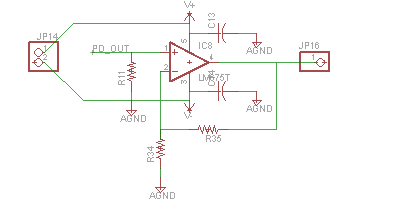
Finally all of the portions of the signal were passed through a summing amplifier before being passed to the power op amp. The LM675 is a power op amp from TI. As the motors were expected to draw 2-3A, depending whether we were driving from a power supply or from batteries, the op amp we used to drive the motor needed to be able to source this amount of current. The op amp also served as a gain stage, multiplied the input by 10x to achieve the maximum swing of +/-30V. Note: by keeping one side of the motor constantly grounded and simply modifying the other side to be positive or negative for direction, we were able to reduce the logic and delays required to switch directions. During testing, we encountered problems using the LM675 which were eventually traced to input coupling. This would result in strange input signal degradation when under load. We were able to fix this issue by moving away from a breadboard to a soldered prototype.
One problem we found was the magnetic coupling due to the proximity of the motors. To cost effectively shield against magnetic fields, we provide shielding through a low carbon steel sheet. The steel sheet was cut and bent to create an enclosure around one of the galvanometers. A metal with a relatively high permeability allows magnetic fields to be redirected through the steel and therefore reduce coupling onto the other motor.
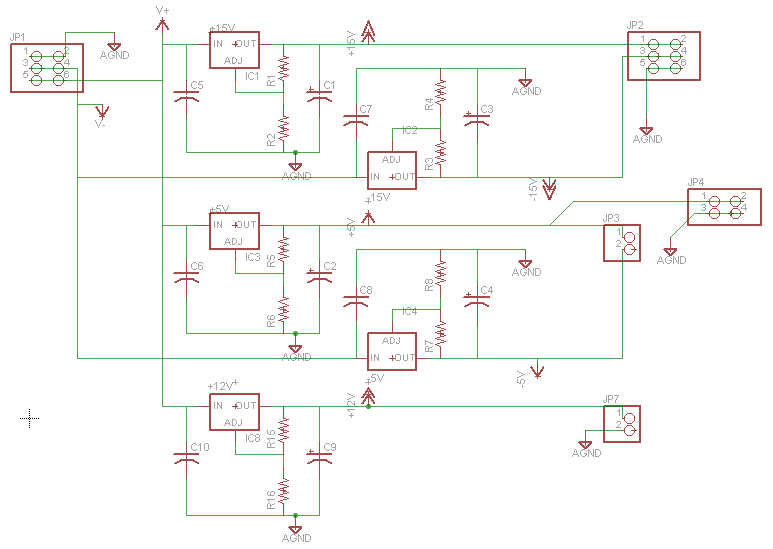
Voltage Regulator Circuit
The voltage regulator board consists of several LM317 and LM337 circuits in order to provide the +15, -15, +5, -5 and 12 volt rails needed for the rest of the project. These chips operate by linear voltage regulation and should be cooled to avoid heat damage.
The LM337 and LM317 are complimentary voltage regulators from TI. In order to run all of the op amps, we needed to have positive and negative voltage rails. We used the +/-5V for the oscillator and the +5V for the microcontroller and FTDI chip. The PD controller board required +/-15V for the op amps. The power op amp simply used the +/-30V straight from the batteries. Power regulators were used for the components where it was important that the voltage remained fairly constant. For example, we needed the oscillator to be very precise or else it would greatly affect the amplitude of our position signal output which would propagate as error in the pd controller. Therefore we could not simply hook up the rail to a battery as that power supply would change over time. Notice, the power op amp was placed on the batteries as we expected a fairly high current draw and did not care as much if the power to each motor decreased by 1V or so.
The voltage regulator board also provides a 12V power source which is used to drive two fans. These fans are essential for the operation of the board since the galvanometers and the LM675 power op-amps require cooling to stay in a safe operating temperature. During testing, we used an infrared thermometer in order to monitor trouble areas and prevent overheating.
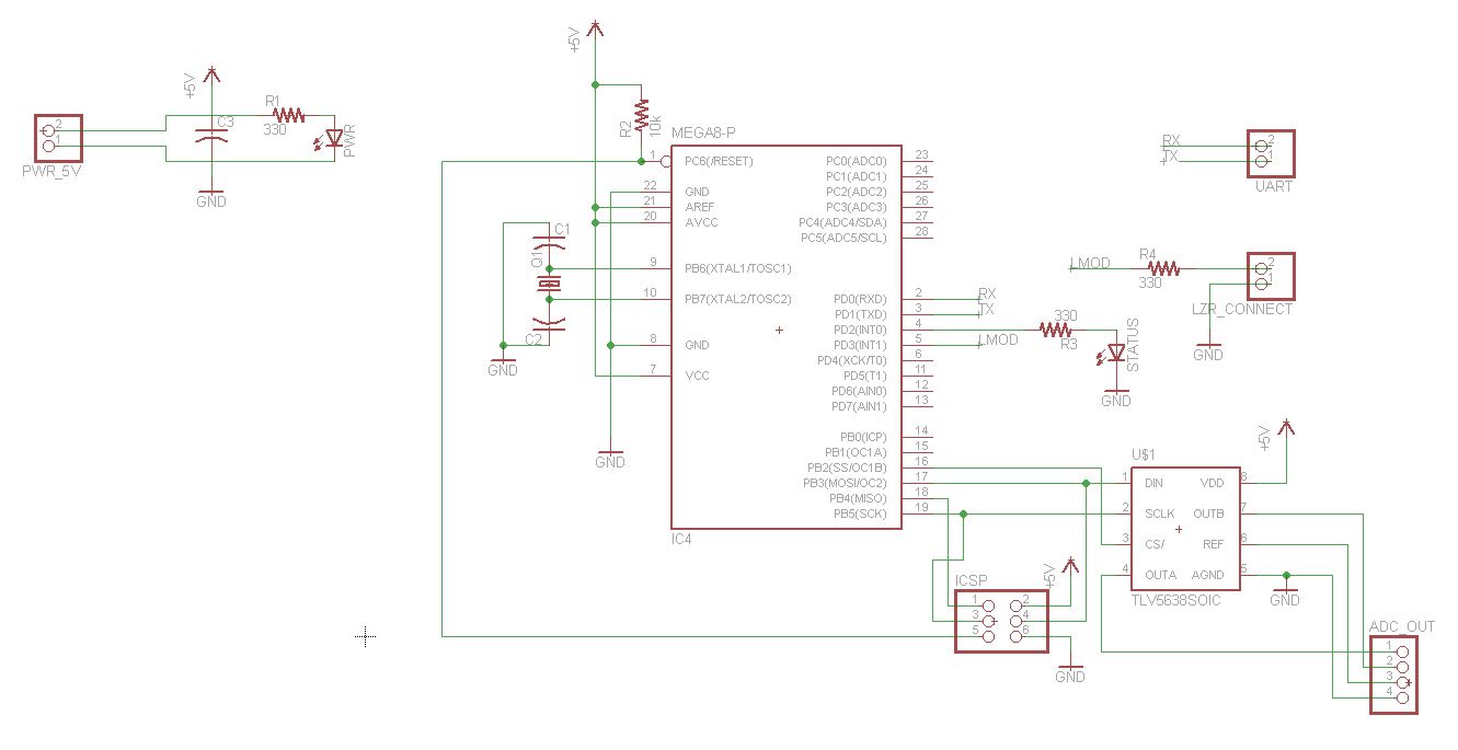
Microcontroller and USB Board
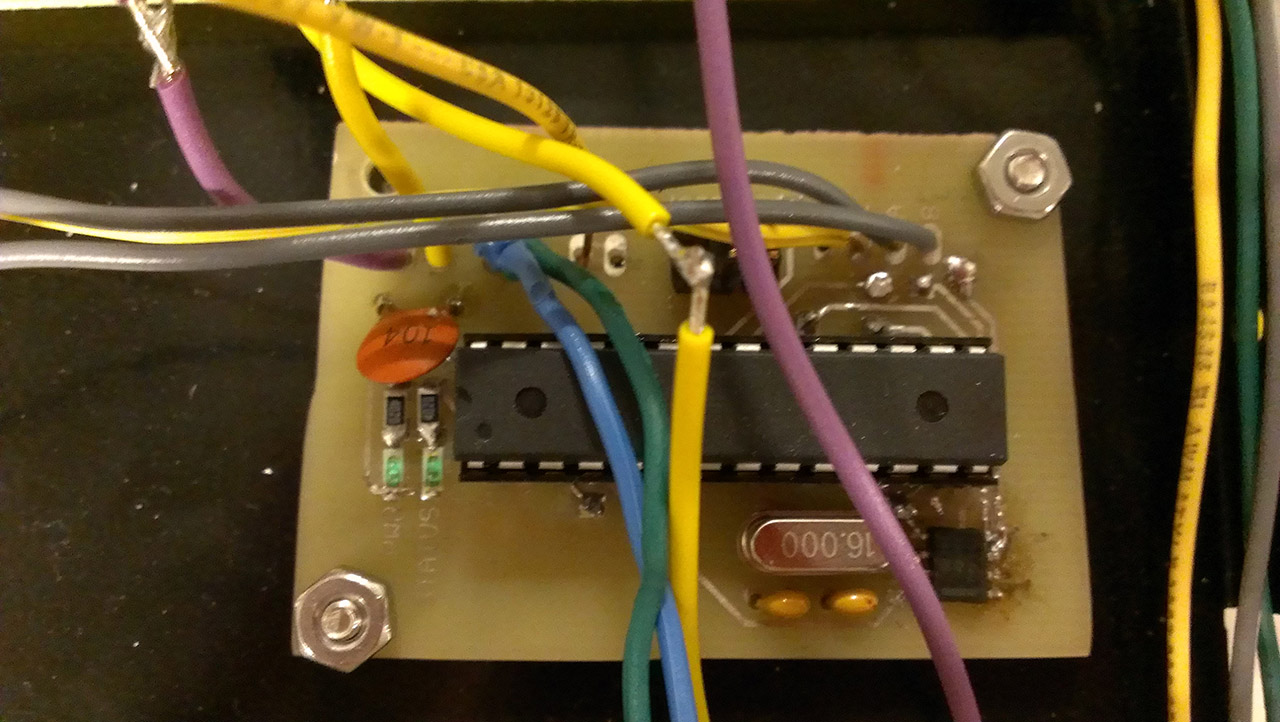
The microcontroller and USB boards are relatively simple in comparison to the rest of the hardware required. The microcontroller board serves as a bare bones microcontroller board (ATMega chip, external 16mhz crystal, ISCP header, UART breakout, voltage input & filtering capacitor) along with a TI dual-channel DAC connected via SPI lines. This DAC's output channels are connected to pin headers for output to the motor control board. The DAC also is configured via software to output a reference voltage of 2.048 volts which it also outputs. This reference voltage is used in combination with the output channel voltage as an input to a differential amplifier circuit in the motor control board.
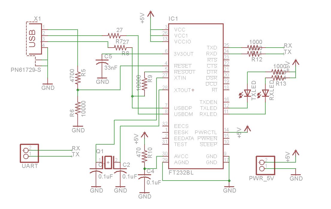
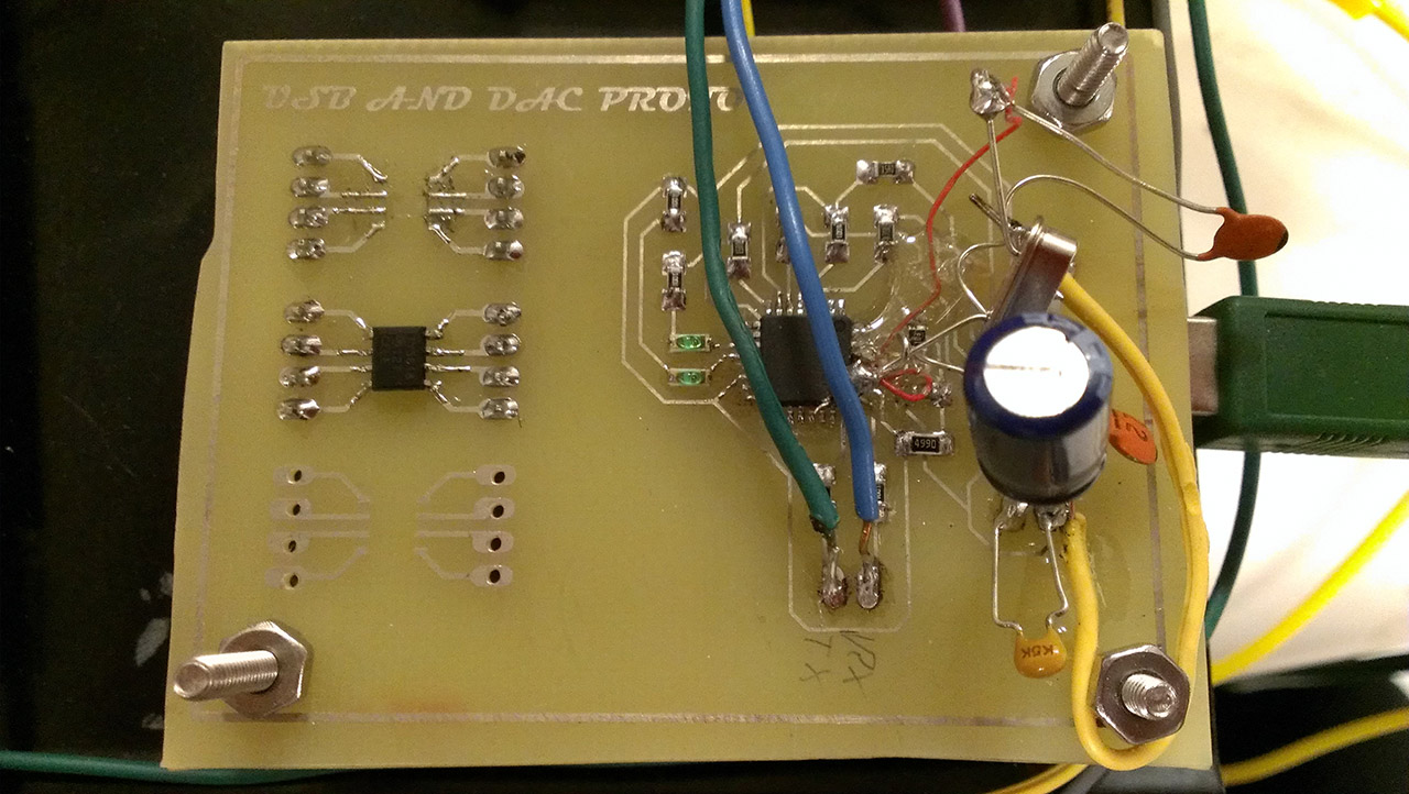
The USB board circuit comes directly from the FTDI chip datasheet's typical usage applications for a self-powered configuration. No modifications were required, though a crystal had to be added post-fabrication resulting in some messy rework.
During testing, we discovered that the microcontroller and USB board would occasionally reset as a result of noise induced by the motors. As a result, we added extra capacitors on the 5V input lines of both boards which effectively solved the problem.
Results
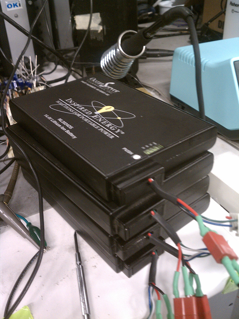
As we were working with Lithium-ion batteries, we decided to test on power supplies as that would help to limit the current draw from our circuit until our signal was stable enough. This however led to one of the main problems we encountered when testing, as the power supply would frequently current limit and therefore would cause the signal to become unstable. When tested on power supplies, we were able to get the step response to roughly 20mS through the p-term and remove the ringing without current limiting. When we moved to batteries, we were able to reduce that time to about 10mS which showed significant improvement on projected image, seen most notably on the projected square wave.
For this project, we decided to run using a closed-loop position. We found that this worked significantly well to improve the quality of the image. As shown earlier, when a simple gain stage was fed to the power op amp, there was significant ringing on the motor position and therefore caused much distortion on the image. When the derivative term was added, the noise was greatly reduced and the motor could be driven at higher speeds.
The circuit was also very susceptible to noise. We found when the oscillator was non-symmetric, the position would become very unstable and produce periodic noise at the same frequency as the oscillator. This was solved by reinforcing the solder joints on the oscillator and ultimately using the function generator. In addition, there was a lot of magnetic coupling as the motors were placed very close together. For this reason, we added the steel enclosure which greatly reduced this effect and helped us drive the motors at higher proportional gain.
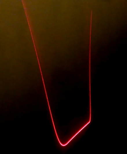
We were able to draw basic shapes using the laser projector. In the video above, we show the laser projector drawing a block better "A" (which ideally looks like this). Since the scan rate of the laser is slower than the frame rate of the video, the letter appears to significantly flicker, more so than it did in real life. Also, at the time this video was taken, there was quite a bit of noise in our circuit which translated to noise in our laser projections. We were able to cut down on this by switching to battery power and by adding the steel enclosure to reduce magnetic coupling between the motors. Further tuning will likely produce higher quality images at more desirable scan rate.
Conclusions
The laser projector was made successfully for the final project of ECE 4760. Every part of this projector was designed and made by hand, though a large part of the design was based off of the work of ChaN. Especially because each part was made by hand, this was a challenging endeavor, as each subsection (mechanical, electrical, and software) had its own set of problems to solve. Even with a working projector, there are many improvements that could be made for the future. As can be seen by the results and motivation, this project is mainly an R&D pursuit, rather than a plan for a commercial product.
Future Improvements
Overall, the project was successful, but there was room for improvement in all subsections of this project. One main issue was the fact that some of the boards needed to be accessed from the bottom of the boards, and so needed to be mounted to the tray vertically, instead of horizontally, as most assemblies are made. The assembly of all hardware onto the metal tray could also have been improved. An easier method of mounting all of the boards to the tray could also have been devised.
A more secure method of holding the coils to the enclosure plates than using zip-ties could also have been devised. Metal brackets could have been machined to hold the coils down, or the coils could have been solidified with resin so that the only thing needed would have been to locate the coils to enclose the rotor.
Intellectual Property Considerations
All of the intellectual property regarding the implementation of this laser projector belong to us because we did not actively search for patents or current publications for the design. We did not sign any non-disclosure agreements to obtain any of the parts that were sampled for this project. Code from the public domain or open source projects was also not directly used for this project (We did use open source programs like make for the purposes of generating our own software).
Furthermore, we are open to the idea that other research/project groups can use our design as a building block to make further improvements to the design. As such, we are releasing our project including its source code under the MIT License. For a listing of the source code, see the code listing section below.
Ethical Considerations
Throughout the process of developing the laser projector, we strived to maintain the highest degree of ethical integrity, as dictated by the IEEE code of ethics. We kept safety for ourselves and for others in mind at all times, by especially trying to minimize as much as possible any hazards related to our hardware (like exposed wires or sharp edges). We also followed the safety protocols dictated by the safety standards mentioned in the Standards section under High Level Design. Before any testing was performed with the laser, we made sure that the rest of the system was operating safely. We also made sure to test the galvanometers separately first, starting with a low-amplitude signal to ensure that the rotor would not be moving too fast.
While building our project, we took precautions while dealing with dangerous tools like soldering irons and mills by wearing safety glasses and ensuring the materials being worked on were securely held in place.
Legal Considerations
Our project does not use or produce wireless communication so we are not in violation of any FCC legal regulations.
Our system is not intended for medical use. Therefore, we are not in violation of any medical device regulations.
Appendix A: Code
Commented Code Listing
Our code (both for the microcontroller and the high level software) is available publicly on GitHub at the following link: https://github.com/jheidel/ece4760-lab5.
Schematics
Motor Control Board
Position Detection Circuit
PD Feedback Control
LM675 power op-amp motor driver
Layout of the board in motor control board (position detection + PD control + LM675 amplifier) in Eagle
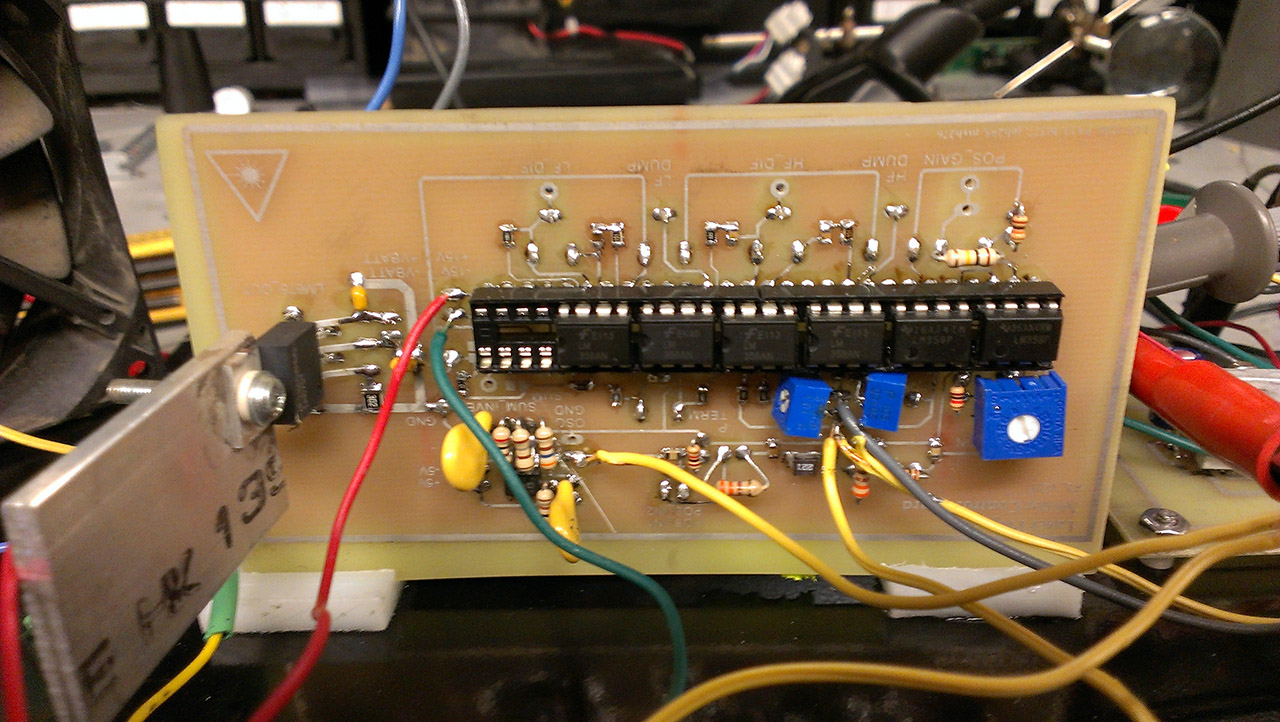
Final board front
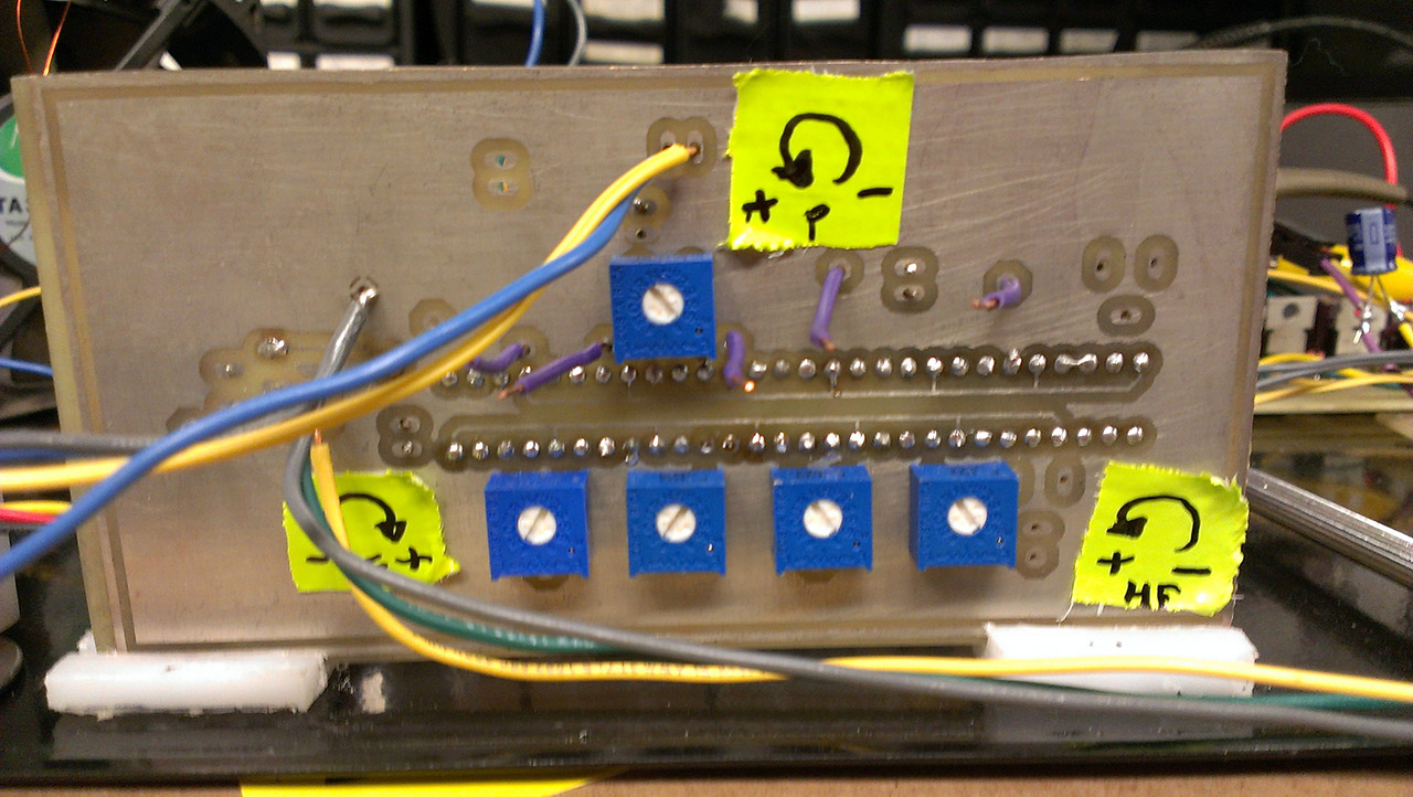
Final board back
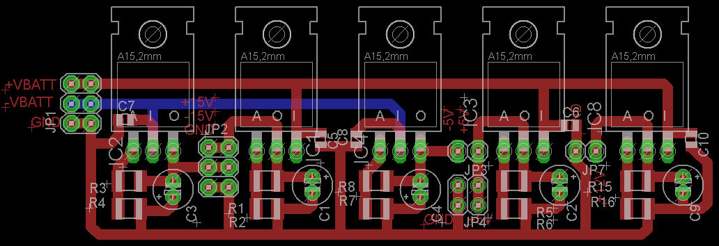
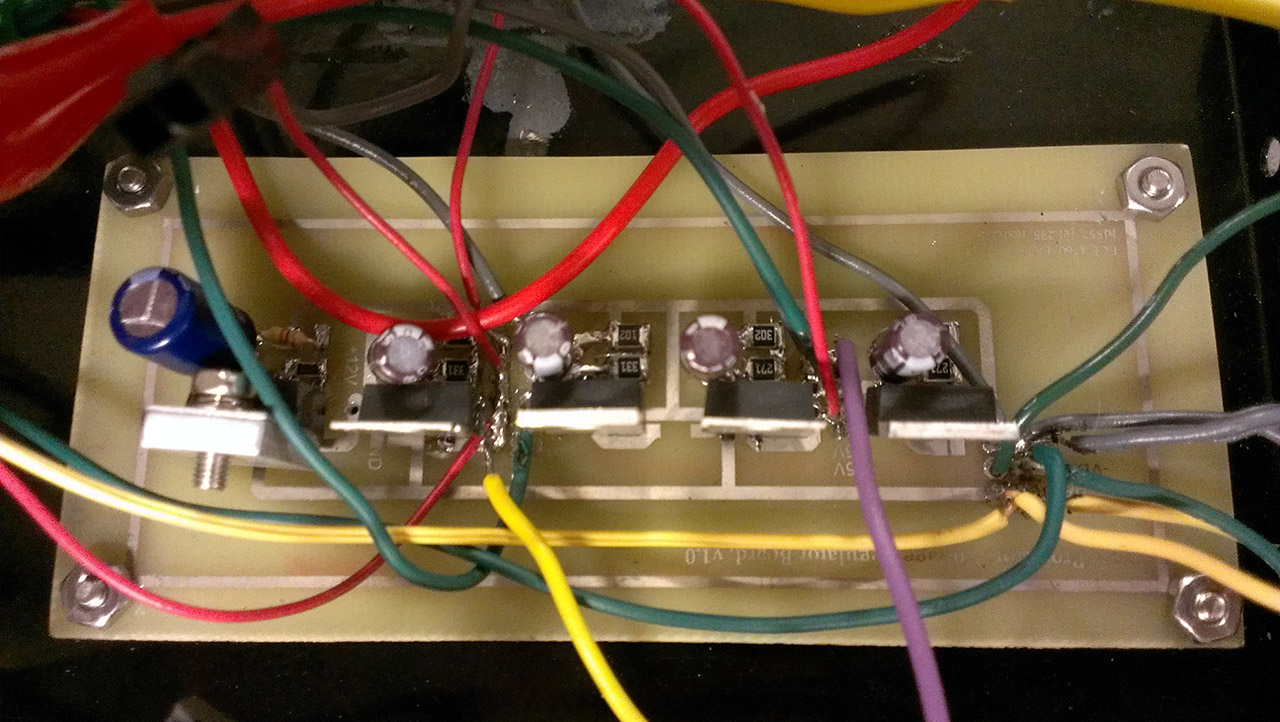
Power Regulation Board
Board schematic
Board layout in Eagle
After population
Control Board
Microcontroller board schematic
USB interface board schematic
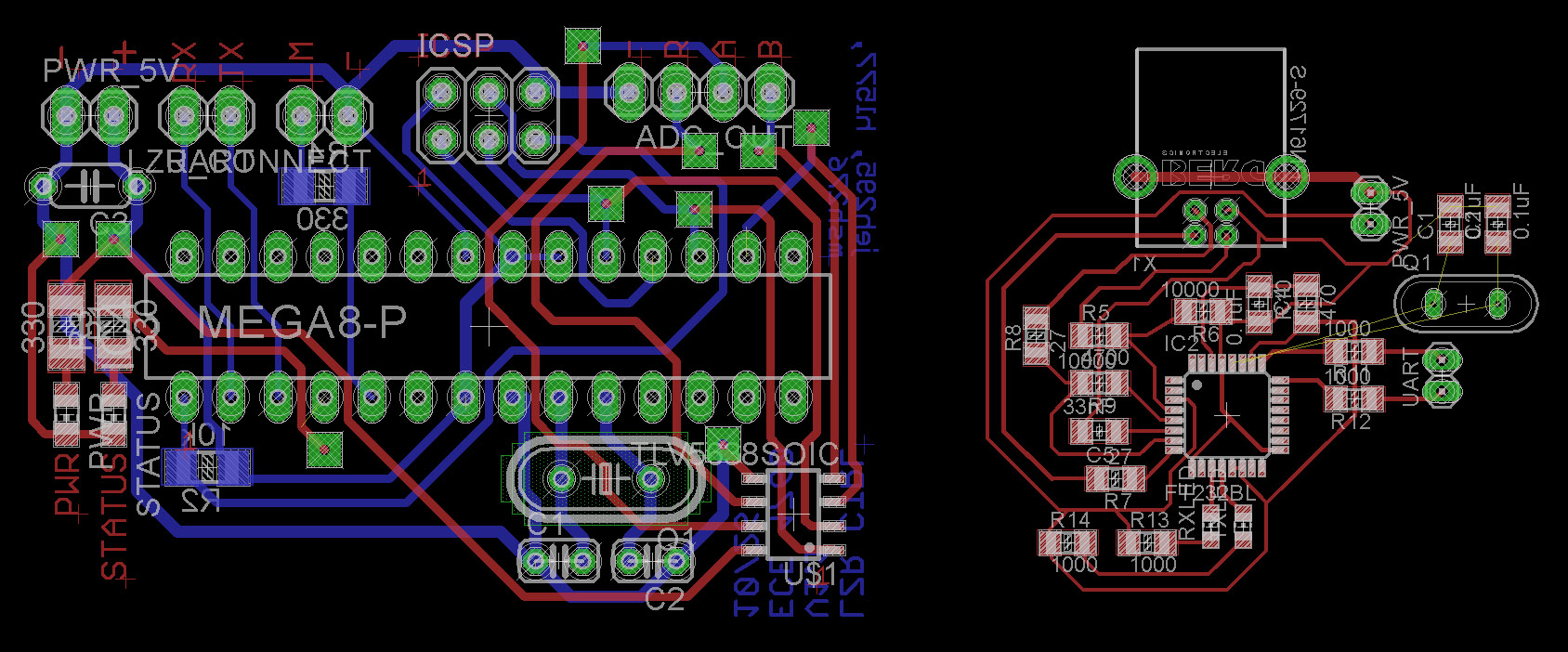
Layout of microcontroller and USB board in Eagle
Microcontroller board after population
USB interface board after population (and rework crystal & capacitors added)
Appendix B: Budget
Part Name
Part Number
Vendor
Quantity
Price
Total
ATmega328
ATMEGA328-PU-ND
Digi-Key
1
2.88
2.88
PC Board
N/A
Parts Express
1
12.33
12.33
Motor Shafts
1327K93
McMaster-Carr
2
2.84
5.68
Bearings
60355K501
McMaster-Carr
4
5.57
22.28
Shaft Collar
9414T3
McMaster-Carr
4
0.87
3.48
Cyl. Magnets
D4X0DIA-N52
K&J Magnetics
2
2.79
4.58
TTL Laser Diode
1056
Adafruit
1
18.95
18.95
LM741 OpAmp
296-11106-5-ND
Digikey
16
0.51
SAMPLED
28pin DIP Socket
N/A
ThaiShine
4
0.28
1.12
Potentiometer
N/A
Prof.Land
18
1.00
18.00
TLV5638
TLV5638ID
Texas Instruments
1
5.65
SAMPLED
LM675
LM675T/NOPB
Texas Instruments
4
2.05
SAMPLED
LM337
LM337KCSE3
Texas Instruments
2
0.40
SAMPLED
LM317
LM317KCT
Texas Instruments
3
0.27
SAMPLED
4S Li-Ion Battery
NL2024OS 66-00001-00
Ocean Server
4
N/A
SALVAGE
USB Female Type B Connector
00139
Sparkfun
1
1.25
1.25
2"x1" Steel Sheet
N/A
Home Depot
1/10
10.00
1.00
Final Total
91.55
Parts List
The following parts are used in the schematics provided above.
We would like to thank Bruce Land and Tian Gao for their guidance on the ideas behind this project and their insight into debugging the system. We would also like to thank the developers of
the Eagle PCB, and GitHub for public repository hosting.


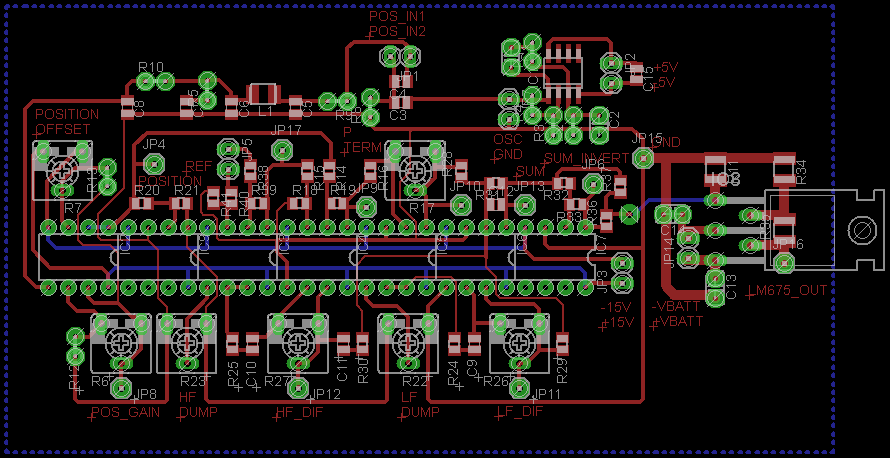 Layout of the board in motor control board (position detection + PD control + LM675 amplifier) in Eagle