ECE
4760 Final Project: Car Parking Video Game
by Lu Liu (ll654), Xu Chen (xc255)
1. Introduction
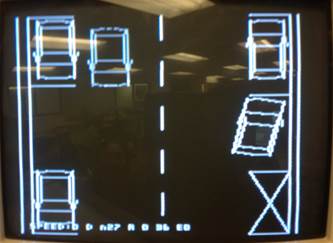
The game consists of two levels. In each level, a LCD TV screen displays the 2-D top view of the a parking lot, and the player needs to park the car into the proper parking spot by operating on a fake steering wheel, gas/brake pedals and gear stick.
On the hardware side, for user control interface, we have built the fake steering wheel, gas/brake pedals, gear stick with basic wood board, hinges, springs, screws, switches, accelerometers, potentiometers, etc. For other parts (display and computation) in the system, we have used the LCD TV screen and Mega 1284 microcontroller which are supplied by lab. These are essential hardware equipment for this project.
On the software side, we have coded the drivers for steering wheel with accelerometer readings, the brake and gas level with potentiometer readings, the gear stick with switch readings. Also, we have applied the mathematic calculations and matrix conversion for car coordinate computation algorithm.
2. High Level Design
(1) Rationale and sources of
your project idea
According to
statistics, in 2012, 13% of national wide car accident
claims occurred in parking lot. Some of the common causes are parking lot
congestion, blind spot when backing out, too much focus on finding a spot, etc.
The idea behind this project, besides enjoy the video game itself, is to aid
people developing parking skills. Also, the video game provides a 2D view of a
parking lot so that it gains players an alternative sense of driving as well as
understanding for vehicle motions.
The rationale of this project is to build a fake user control interface,
sense the user's driving intention through sensor data acquisition and analysis
in microcontroller and output the results in the LCD monitor.
(2) Logical structure and
background math
The logical structure of this project can be divided into three parts: hardware building, sensor data analysis and video game processing.
The
hardware building constructs a user control interface and places the sensors in
the hardware accordingly. It establishes hardware for the user-machine
communication system which includes a steering wheel, gas and brake pedals, and
a gear stick. The faking control devices built are simple yet good enough to
provide players a realistic feeling of maneuvering inside a vehicle. (Please
see the section ‘Program/Hardware design’ below for more details on
control interface.)
The sensor data analysis is low level software suite (driver code)
development which uses the mega1284 microcontroller and translates the readings
from the sensors (built on the hardware devices) into car status indicators.
This will be further used in later video game development. (Please see the section
‘Program/Hardware design’ below for
more details.)
The video game processing involves many background mathematic calculations such car coordinate computation, car rotation matrix constructions, etc. It also includes video signal processing, such as line plot, character printing and so on. (Please also see the section below ‘Program/Hardware design’ for more details.)
The program uses the function ‘video_car’ to compute coordinates of a car and plot it onto the LCD display. The ‘car’ is constructed using 22 points based on the head two points (point 0 and point 1) given. Below is diagram and coordinate mapping of the car.

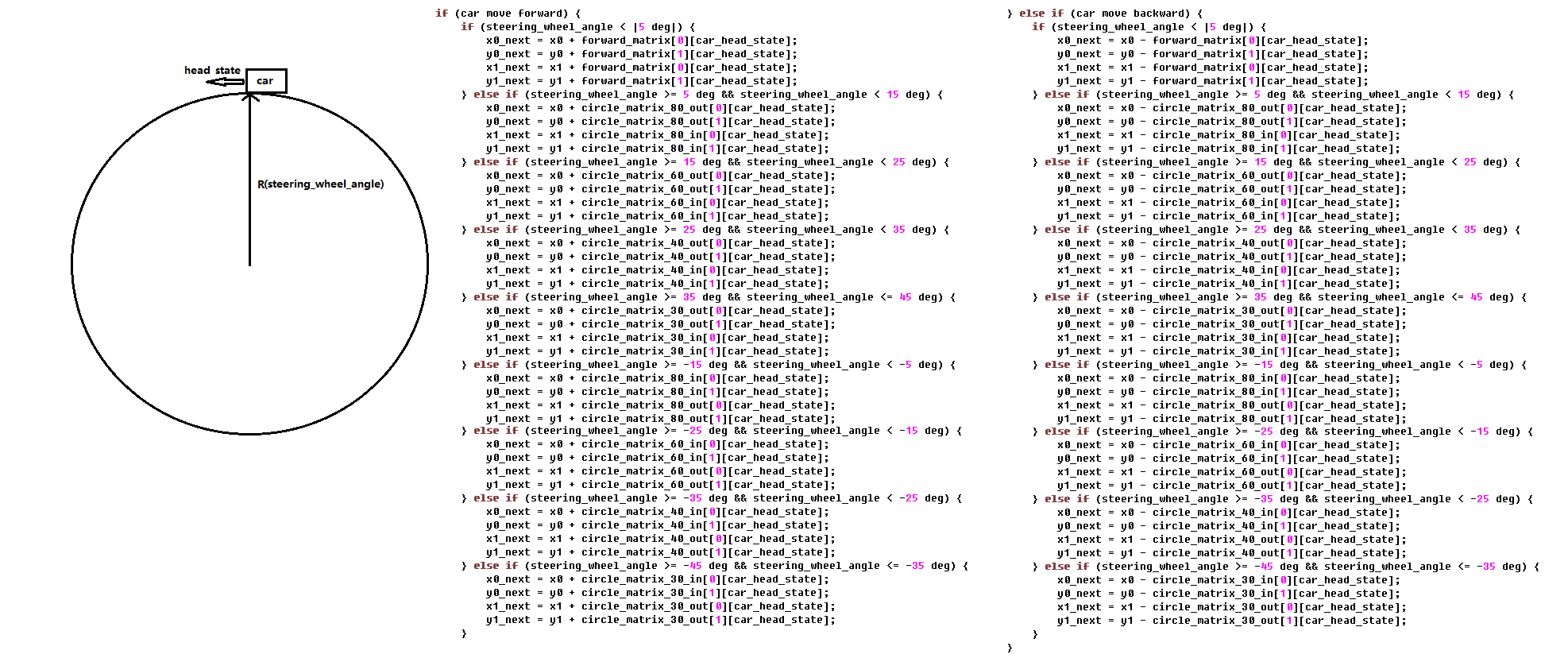
Car Rotation Matrix
The program uses matrices to compute the head points (points 0 and 1 above) of the car during its movement. Below is a diagram and pseudo-code for coordinate computation. The matrices store the coordinates increments of both x and y direction depending on the current car head direction (head state). And different matrices are used for different car trace circles. (When the turning angle of the steering wheel is large, the car will move in smaller circles compared to the case when the angle is small, the car will move in large circles.) Thus, the next state of coordinates of the car depends on its current coordinates, its moving direction (forward or backward), its current head state and the steering wheel turning angle.
(3) Hardware/software tradeoffs
The hardware and software tradeoff in this
project mainly involves the complexity and capability tradeoff. First of all,
in the hardware side, the capability of the mega1284 microcontroller is limited
in terms of memory capacity and processing speed. For example, in this project,
the computation time for the car coordinate and rotation is limited by the
video frame refreshing speed (most of the microcontroller's CPU are consumed by
refreshing the video output to the LCD monitor). Thus, the sensor reading
resolution is limited. The more complex the hardware, the more sensors would be
required and more sensor readings as well as processing time from the
microcontroller would be needed. Too complex in the hardware design would
result in microcontroller incapable of refreshing he LCD display in time, that
is, refreshing rate on LCD. Therefore, there is a tradeoff between complexity
and capability in the hardware. Similarly, in the software side, the more
complexity in car coordination computation, the more time would be required in
the microcontroller processing. For example, if we continuously compute the car
coordinates in rotation movement, lots of processing time would be needed for
trigonometry. Thus, instead, we chose to discretely pre-compute rotation
coordinates in a matrix which saves us processing time at the price of slightly
discontinuous movement in the car rotation.
(4) Relationship to available IEEE, ISO,
ANSI, DIN, and other standards.
This project will be following IEEE. The connection between the MCU and
TV display will use the US standard RS- 170A (NTSC) .
And the data transmission between sensors and MCU will follow the SPI standard.
(5) Patents, copyrights, and trademarks
The video output plots are referenced from previous projects of
// Mega644
version by Shane Pryor
// mod by brl4@cornell.edu'
3. Program/Hardware Design
(1) Program details.
The program for this video game consists of two parts: low-level driver
code and high-level video game design. (The details are described in the table
below.)
One tricky part in the program is the design of an auto-adjust system on
car current direction variable 'angle_state'. The 'angle_state' variable is used to indicate the car heading
direction. This variable is estimated through the use of matrices during car
turning movement. Thus, the error of inaccuracy is inevitable and error gets
accumulated over time. To solve the problem, we code an auto adjust function 'adjust_angle_state' to adjust the 'angle_state'
variable according to the coordinate of the car. However, this function is slow
in computation and if called on every cycle of LCD frame update, it will slow
down the LCD refresh rate. Therefore, we chose to only update it when the car
is not moving (when user steps on the brake pedal). In this way, the 'adjust_angle_state' function acts
as a feedback system that synchronizes the coordinates of the car with the 'angle_state', yet its slow computation does not get in the
way of refreshing LCD display.
The low- level driver functions use the ADC in the microcontroller to read the
sensor readings and return the value as the status indication of the vehicle
driven by the player. This includes the following functions:
Driver functions:
|
int potentiometer (int voltage) |
This function is used as gas pedal level indication. It receives the ADC readings of a potentiometer and returns the value 1 to 3 indicating the gas pedal level. |
|
int abs_wheel_angle (char acc_0, char acc_1, int prev_wheel_angle) |
This function is used to indicate the absolute position of the steering wheel. It receives the ADC readings from two accelerometers attached to the steering wheel and returns the an 0-359 integer indicating the absolute turning angle of the steering wheel. |
|
int relative_wheel_angle (int init_angle, int acc_0, int acc_1) |
This function is used to indicate the relative steering wheel angle. It receives an 'init_angle' as previous absolute steering wheel angle (ranging from 0 to 359) and two accelerometers readings and returns an integer indicating the relative turning angle of the steering wheel. |
|
int car_angle_compute (int wheel_angle)
|
This function is used to indicate the absolute car wheel angle. It receives a steering wheel angle (ranging from -450 to 450) and returns the corresponding car wheel turning angle (ranging from -45 to 45). |
Video game design functions:
|
char video_line_set (char x1, char y1, char x2, char y2) |
This function checks if any point on a line is 'white'. It returns 1 if a point on the line is white. |
|
int video_rectangle (int x0, int y0, int x1, int y1, float length, int *coord, int plot, char c) |
This function computes and plots a rectangle of length 'length'. It receives two points' coordinates as two of the points on the rectangle and uses the existing 'video_line' to draw a rectangle. It also puts all the four points' coordinates of the rectangle into the 'coord' array. When the 'plot' is set, the function will plot the rectangle with color indicated by 'c'. When not set, only the coordinate will be computed. The function will also return 1 when the coordinates are out of bound. (x coordinate shall range from 0 to 160 and y coordinate shall range from 0 to 200.) |
|
void video_rectangle_fix (unsigned int x0, unsigned int y0, unsigned int x1, unsigned int y1, unsigned int length, unsigned int *coord) |
This function computes the coordinates of an rectangle with the data type of 'fix'. It receives two points' coordinate on the rectangle and computes the other two points with the 'length' given. It puts the results of all four points in the 'coord' array. |
|
int video_car (int x0, int y0, int x1, int y1, int plot, char c) |
This function plots a car. It receives two points from the 'head' of the car and plots a 21 point car on the LCD monitor. If the 'plot' is set to 1, it will plot the car with color indicated by 'c'. If the 'plot' is set to 0, it will not plot anything. This function also returns 1 if any point on the computed car is out of bound. (x coordinate shall range from 0 to 160 and y coordinate shall range from 0 to 200.) |
|
int start_car (unsigned int *x0, unsigned int *y0, unsigned int *x1, unsigned int *y1, int speed) |
This function drives the car forward/backward with speed equals 'speed'. It receives two points from the head of the car of data type 'fix' as pointers and puts the new position in them when done. It also returns 1 when the new car position is out of bound (in this case, the position is not updated in the pointers). |
|
void plot_parking_lot_0 (void) |
This function plots parking lot type 0. |
|
void plot_parking_lot_1 (void) |
This function plots parking lot type 1. |
|
void adjust_angle_state (unsigned int x0, unsigned int y0, unsigned int x1, unsigned int y1, int *idx, int *idx_2) |
This function adjusts the car variable 'angle_state' (the current car head direction) according to the current car coordinate. It is used as a feedback function to auto adjust 'angle_state' variable set through matrices during car rotation. |
|
int check_car (int x0, int y0, int x1, int y1) |
This function checks if a car is intact, i.e. if the car is fully plotted. It returns 1 if the car is NOT fully plotted. This function is used at the end of the game to check if user has hit any car during parking. |
|
int check_parking (unsigned int x0, unsigned int y0, unsigned int x1, unsigned int y1, int x0_line, int y0_line, int x1_line, int y1_line) |
This function checks if a car is parked in the specified parking lot. It returns one if the car is NOT parked properly. This function is used at the end of the game to check if user has parked the car correctly. |
|
int check_parking_lot_0 (void) |
This function checks parking result in the parking lot 0. It returns 1 if any cars in the parking lot is hit by the user, returns 2 if the user's car is not parked properly in the spot and returns 3 if any car is hit and user's car is not in the spot. It returns 0 if the parking is success. |
|
int check_parking_lot_1 (void) |
This function checks parking result in the parking lot 1. It returns 1 if any cars in the parking lot is hit by the user, returns 2 if the user's car is not parked properly in the spot and returns 3 if any car is hit and user's car is not in the spot. It returns 0 if the parking is success. |
|
int check_line (int x0, int y0, int x1, int y1, int x2, int y2, int x3, int y3, int line_x0, int line_y0, int line_x1, int line_y1) |
This function checks if a line is crossed by the car. It returns 1 if it is and returns 0 is not. This function is constantly checked during the game so that if the car runs over a line in parking lot, the line shall be redrawn after the car passed. |
|
void redraw_a_line_parking_lot_0 (int *cross, int *prev_cross) |
This function checks if a line in parking lot 0 is crossed over by user's car and redraws the line if the user's car has passed over. |
|
void redraw_a_line_parking_lot_1 (int *cross, int *prev_cross) |
This function checks if a line in parking lot 1 is crossed over by user's car and redraws the line if the user's car has passed over. |
|
void erase_screen (void) |
This function erases the whole screen. |
|
int main () |
The main function does the initialization of the video game, including correctly configuring the microcontroller, plotting the parking lot, initialize car variables. Then it constantly execute the video game (in an infinite loop) by updating sensor readings, updating the car coordinates, computing the car variables, displaying the car status readings onto the LCD monitor and checking the results when done. |
(2) Hardware details.
The hardware design in this project is not so difficult. The basic hardware design strategy is to use accelerometers to measure the steering wheel angle, and use potentiometers to detect the brake and gas pedal, and in addition, we use a switch to act as a gear stick. The tricky thing in the project is how to connect the user interfaces with the sensors, so that the sensors can generate useful control signals to the microcontroller.
We can suppose that the steering wheel rotates in x-z plane, and we verified that we can use two Z axis accelerometers which are placed at 90o to indicate all the 360 degree in the plane. The accelerometer we use is MMA1260D. It's a low-g, Z axis, micromachined accelerometer, and can generate quite stable signal. So we hot glue two Z axis accelerometers to the steering wheel as shown below, and connect them with the ADC input port of the microcontroller.
The
figure below shows how the two accelerometers placed on the steering wheel.
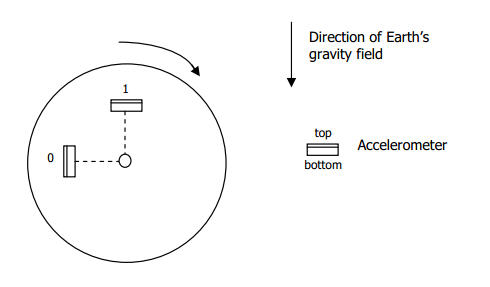
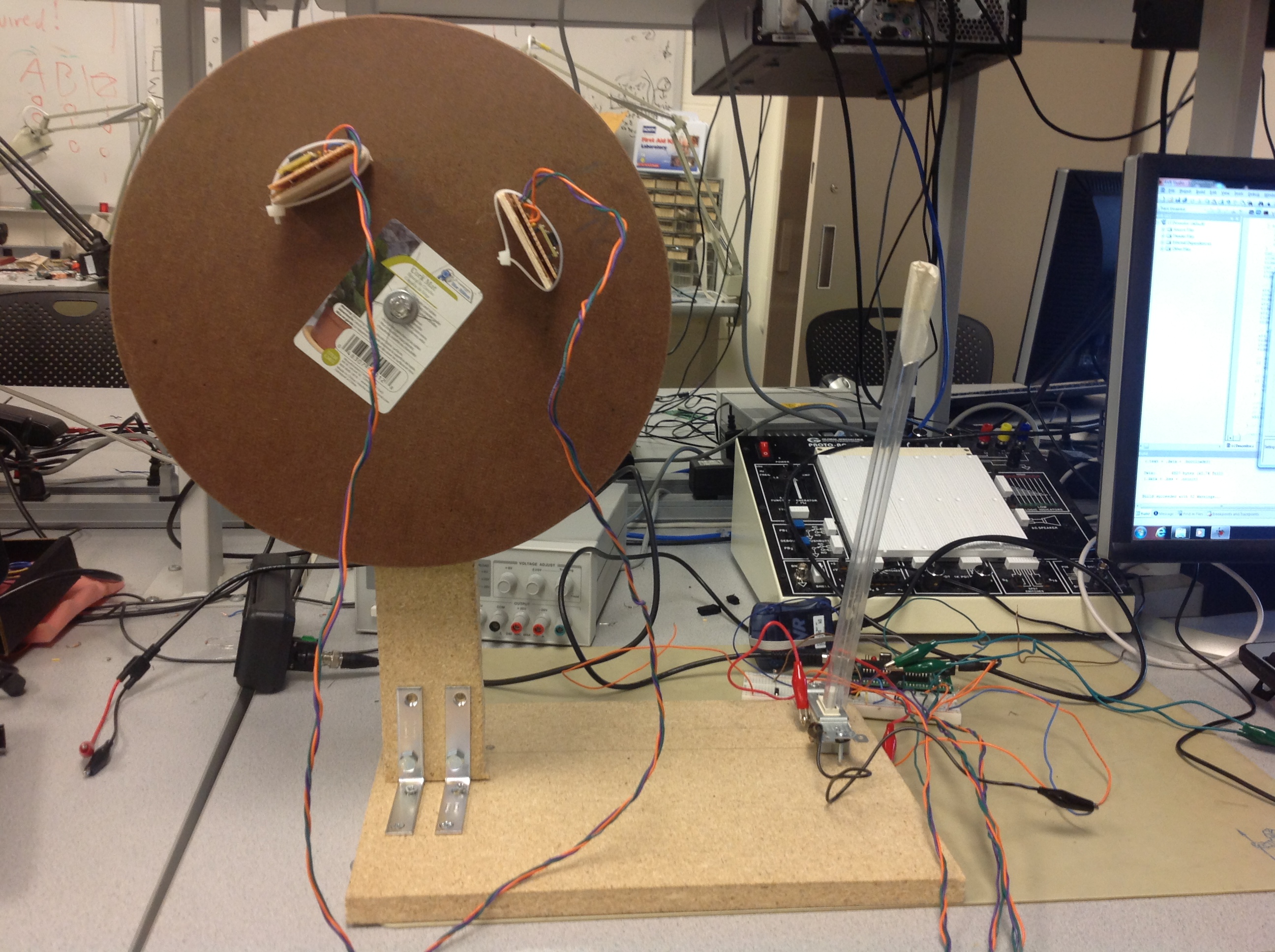
Figure 1. Steering wheel with accelerometers and gear stick
Below are two figures that can illustrate how we verify the mapping the two accelerometers' outputs and the degree. When placing these two accelerometers on the steering wheel as Figure 1, and assuming that the state in Figure 1 corresponds to 0 degree in the table below and also the steering wheel spins clockwise, we can imply that each degree corresponds to a unique combination of the two outputs of accelerometers, although in the table below, we only list some specific degrees.
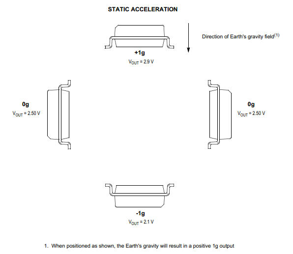
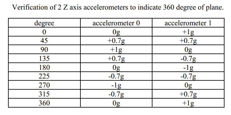
Figure 2. Static acceleration (Reference: datasheet of MMA1260d) Figure 3. Mapping of accelerometers' outputs and degrees in plane
We implement the gas and brake pedals using hinges and springs, and add
one potentiometer for each pedal. So our hardware for pedals is using the
potentiometers to construct a simple bleeder circuit. The potentiometer we
use has the maximum resistance of 87k Ohm. When the pedal is not
being stepped on, the resistance is about 1.8k Ohm, so here we
use the 5.1k Ohm resistor in the bleeder circuit to make the output
range large enough.
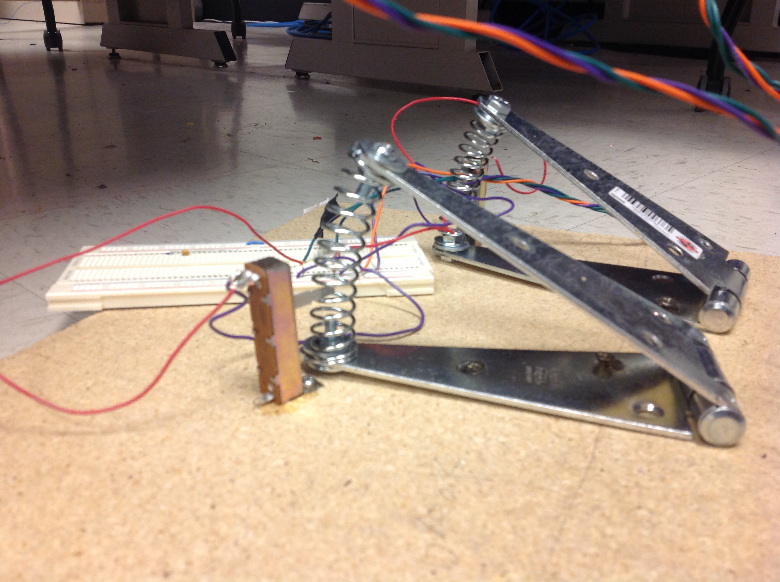
Figure 4. Pedal and potentiometer
The gear stick is composed of a switch which is used commonly in life. Although the switch specification indicates that it is used in the 110V AC, we tested and found that it can be used as a regular switch in 5V DC. It is shown in Figure 1.
Then we connect the output signals from accelerometers and the potentiometers to different channels of the mega1284p internal ADC. And in every loop, the microcontroller will read the ADC outputs and use them to control the car movement. The gear stick acts as a general switch, and is connected to PINB2 through a resistor. Another circuit in this project is the circuit to connect the microcontroller to the TV. The circuit is shown in Appendix. We use the circuit of connecting the accelerometer to microcontroller which is provided in the datasheet of MMA1260D, and the MCU-TV circuit provided in webpage of the ECE4760 Video Generation with Atmel Mega644/1284 and GCC.
4. Results of the design
Our designed video game consists of two parking stages with the following
features:
1. User configurable stage selection.
2. A finish and a restart button.
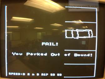
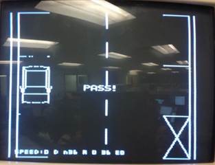
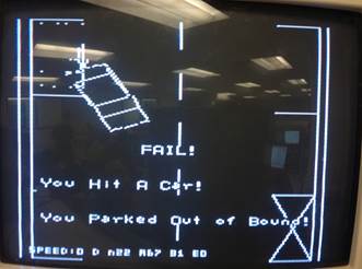
3. Auto parking result checking and status report when finished.
4. A complete user control interface includes steering wheel, brake pedal, gas
pedal and gear stick.
5. Auto parking lot line recovering after user's car cross over.
6. Car hit evidence shown at result checking stage.
Our project involves many human interactions to control the movement of the car
in the parking lot. When parking, to get a better control, we need the car to
move slowly in the LCD TV. So, we need the car to move less than a pixel on the
TV for each frame refresh period, and it will result in the computation for
data type 'fix' which is time consuming. Therefore, when the car is moving on
the TV, it seems shaky and sometimes less continuous. This is also because of
the discrete movement computation logic. And also the pixel on the LCD screen
is not square, so the car changes shape slightly during it is rotating.
The video sync rate is 15.7 kHz, which can be measured in PIND0 by oscilloscope
and thus the total frame refreshing rate is 1/60s.
For this design, the main issue in safety is the hardware construction, i.e. building the steering wheel, pedals, gear stick, etc. The process involves cutting wooden board, soldering circuit board and so on. We enforce our safety by consulting instructors in each step for using tools. Also, we wore safety glasses and gloves whenever required. Our design has no wireless communications involved so we didn't encounter many interference issues with other people's design. The video game we designed can be operated by most people whether with or without driving experience. The game itself requires user to be able to fully control the steering wheel, gas and brake pedals, gear stick and switches and buttons.
5. Conclusions
Our design has met our expectations. It consists of all initially intended
features of fully functioning user control interface, multi-stage,
auto-checking and parking lot line recovery features. The only thing we might
do next time is to further optimize the computation logic (use more
look-up-table than computation) to speed up the video game.
Our design fully conforms to the video standard US standard RS-170A (NTSC) and
video game successfully shows the parking lot and car movement.
As for ethical considerations, the main idea behind this project is to assist
people in practicing parking skills. The game, including all the user control
interfaces, simulates the real driving environment. Thus, the game is intended
to help people with or without driving experience gain some general feelings
and practices of parking a car in parking lots with a safe virtual environment
yet still practical enough. In this way, it contributes to the safety of the
public by helping drivers to park safely and also aiming at reducing accidents
and injuries in parking lots.
Also, in developing stages, we have made the following decisions and actions that conforms with IEEE Code of Ethics. First, some of our basic video functions are referenced from previous projects. We have properly referenced this in both our code and report, thus credit properly the contribution of their work. Second, in the choice of material that we used to construct our hardware equipment, we have chosen to use chipboard rather than whole piece wooden board. This is because it is cheaper and, more importantly, more environmentally friendly compared to whole piece wooden board. Thus, we make decisions consistent with the health and welfare of the public. Also, during our process of building hardware equipment, we have asked instructor for help in using electric tools, such as electric saws and soldering, because the process might cause injuries to us or others if not handled properly. And some process might even result in environmental hazards such as splitting fiber class pieces when cutting circuit board. Thus, by asking for assistance in the tasks that we have no experience with shows our responsibility to improve the understanding of technology and its appropriate application, and potential consequences. Last, in every stage of our design, we have consulted the instructor for viability and safety of our next steps and ideas. Thus, we have maintained and improved our technical competence and undertaken technological tasks after fully disclosure of pertinent limitations.
6.
Appendix
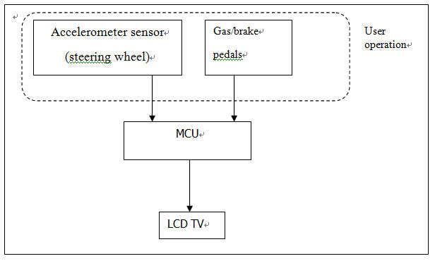
Figure A.1 Block Diagram
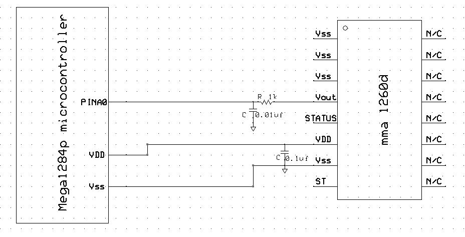
Figure A.2 Accelerometer circuit
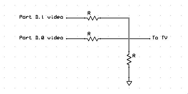
Figure A.3 LCD TV connection
|
Parts |
Number |
Unit prize |
Total prize |
|
Mega1284 |
1 |
$5 |
$5 |
|
Custom PC board |
1 |
$4 |
$4 |
|
White board |
2 |
$6 |
$12 |
|
Small solder board |
1 |
$1 |
$1 |
|
LCD TV |
1 |
$5 |
$5 |
|
Potentiometer |
2 |
$0 |
$0 |
|
Accelerometer |
2 |
$0 |
$0 |
|
Wooden board |
1 |
$4.5 |
$4.5 |
|
Hinges |
2 |
$4 |
$8 |
|
Springs |
2 |
$2.1 |
$4.2 |
|
Miscellaneous |
|
|
$10 |
|
Total |
|
|
$53.7 |
Table A.1 Cost details
Pictures

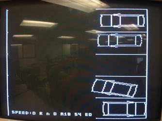
Picture 1: Level 1
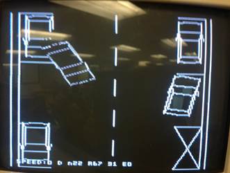
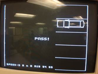
Picture 2: Level 2
7. Reference
Video
plot code from labs in previous year:
Parking lot accident statics:
http://blog.autopartswarehouse.com/2013/10/parking-lot-accidents-prevent- infographic/
MMA1260d datasheet
https://courses.cit.cornell.edu/ee476/FinalProjects/s2006/wl228hl336/New%20Folder/mma1260d.pdf