Introduction top
In this project, we built a music sheet reader, which can identify music sheet in the format of piano roll. Utilizing some hardware materials such as PCB board, spacers and hardboard, we carefully construct a firm station that carries the linear optical array, servos, and light source. Linear optical array connects with Microcontroller with SPI protocol. UART connection is formed between microcontroller and computer to transfer MIDI message.
 Figure 1, Station side view
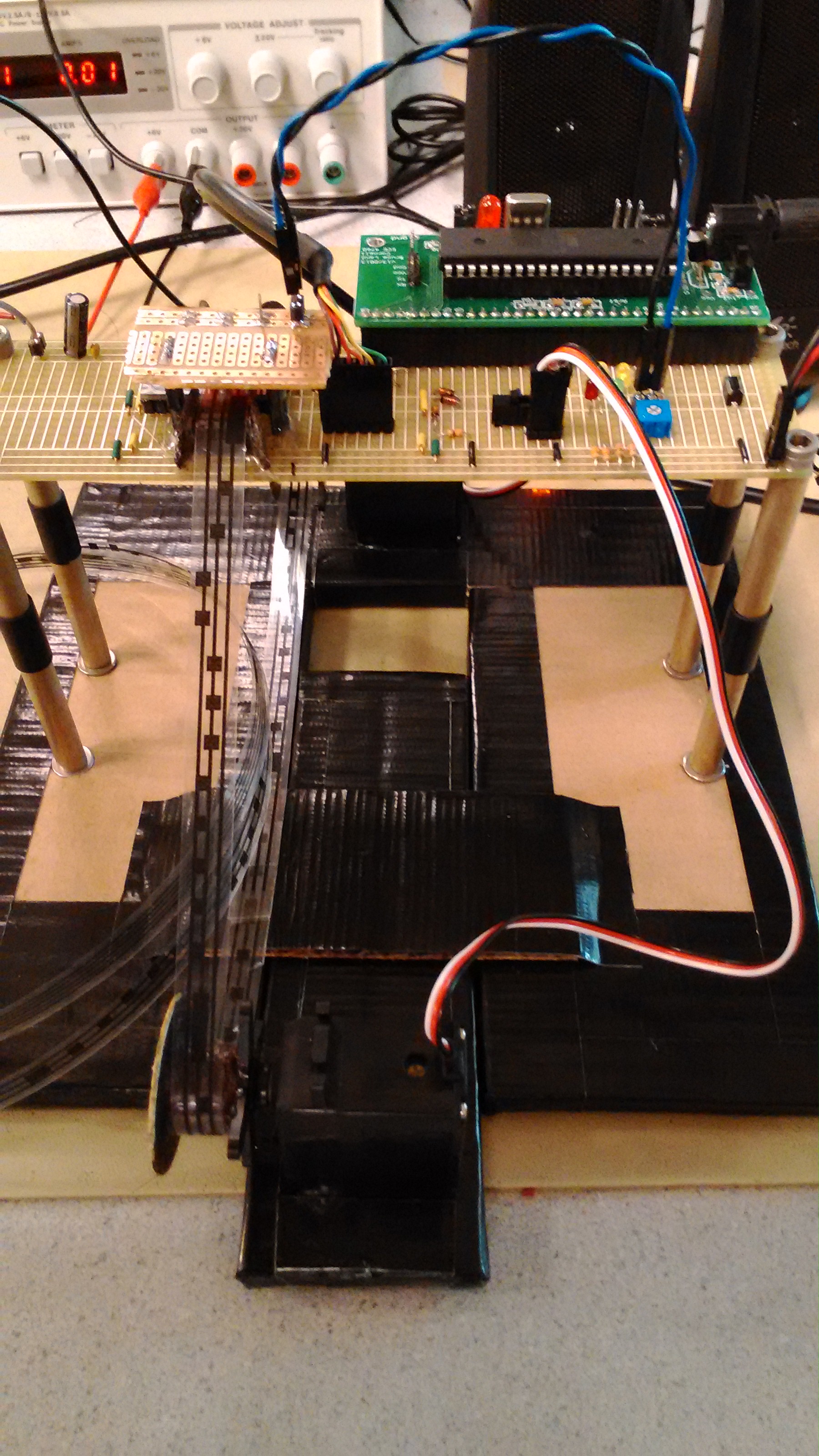 Figure 2, Station top view
High Level Design top
Motivation
Written music in the form of musical scores are usually cryptic to people without formal musical training. Even to those well versed in musical notation, recognizing which note corresponds to a middle C does not mean that they can imagine what middle C sound like just by reading sheet music. Therefore, unless one is trained in sight singing, it is difficult to recognize the melody of a musical piece just by looking at its sheet.
We implemented a music reader that is capable of deciphering an alternate form of musical representation called the “piano roll”. Traditional music box and mechanical piano make use of this kind of representation for recording and playing music automatically. Our implementation uses a 144 x 1 (pixels) linear optical array to scan this form of notation to directly decode and play them back on a personal computer (PC). By spanning the longer dimension across a single octave on the sheet and sliding the sheet music across this array at a reasonable speed, we are able to captures the musical notations. A microcontroller unit (MCU) will be used to decipher the pixels captured by the sensor and decode them into Music Instrument Digital Interface (MIDI) data. The MIDI data can then be fed to a personal computer to synthesize written music in real time.
High Level Block Diagram
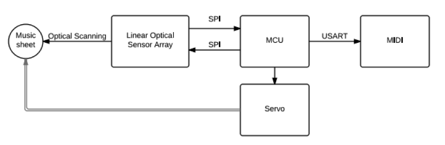
Figure 3: High level block diagram of design
There are 4 high level modules in the music reader: optical sensor, MCU, rotational servo and MIDI. The block diagram shows the relationship between each part under the normal operation.
The optical Sensor module detects the pixels on the music sheet and converts it to binary 0 or 1. After the optical sensor finish integrating the pixel intensities, the MCU will use Serial Peripheral Interface Bus (SPI) to transmit the request and receive data.
The servo is used to assist the rotation of music sheet, since we need to keep the music sheet moving at a steady rate as well as hold the sheet in place horizontally. This module is controlled by MCU directly and running at a constant speed.
The pixels read from the optical sensor array will be decoded into the respective notes, which will then be packaged in the form of MIDI messages and sent out through USART0 to external synthesizer.
Design Tradeoffs
- Instead of printing the music note on the normal paper we print it on the transparent paper, which provides better contrast. Light can penetrate the clear parts of transparent paper but not the dark parts of transparent paper.
- Due to the limit size of the linear array sensor, each line on the staff should be drawn close to each other. The music note should also be small to be accurate. This makes it hard to hand draw the lines and the musical notation.
- While the software of a 5 staff roll was written, the size of sensor array restricted the accuracy of 5 staff roll as the outer lines tend to move out of the sensor region. 3 staff roll was found to work perfectly.
- This implementation is a proof of concept that it is possible to read and play music directly from written notations. Although the notations of piano rolls are simplified compared to actual sheet music, future work can make reading actual notes possible.
Standards Used
- Music Instrument Digital Interface (MIDI): Technical standard for music maintained by MIDI Manufacturers Association. Used for packaging decoded musical notes from optical sensor for synthesis.
- Serial Peripheral Interface (SPI): Communication protocol between optical sensor array and MCU.
- Universal Asynchronous Receive Transmit (UART): Communication protocol on which MIDI messages ride. Used for sending MIDI messages from MCU to PC.
External Software Used
- Hairless MIDI: Serial to USB communication bridge between USART0 serial and PC’s synthesizer.
- Virtual MIDI Piano Keyboard (VMPK): For synthesis from MIDI messages
Hardware top
The idea of our music sheet scanner is to use a form of optical sensor to scan music script and send note message to computer to play the corresponding sound. The core of our system consists of two parts: the sensor and motors. We utilized linear optical array as our sensor to detect lines and notes. Two servos are used to move the music sheet for scanning. Hardware high-level design and circuit schematic are provided below:
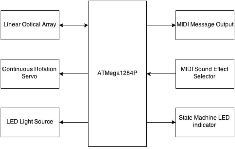
Figure 4: Hardware High-level Design
We also drew a 3D model for our whole system. Two servos and two support structures are used. Linear optical array and LED light source are placed below and above the sheet separately. We lift the solder board up by 4 spacers and connected them to a hard paperboard. Servos are also hot-glued to the paperboard for system stability.
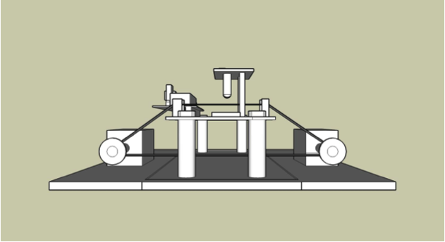 Figure 5a, Hardware 3D Model (1)
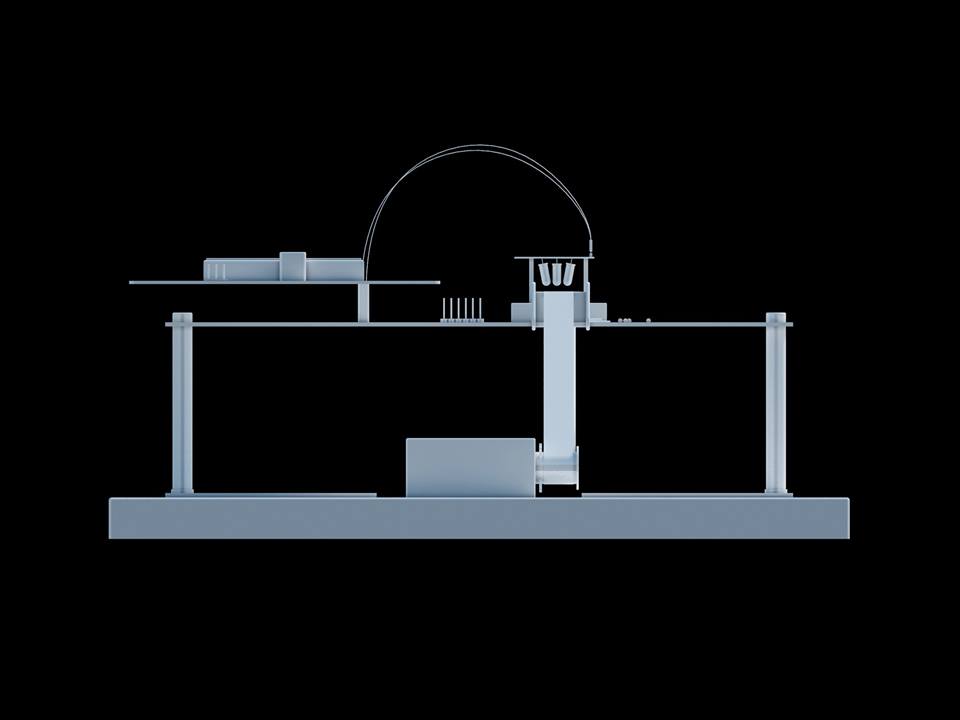 Figure 5b, Hardware 3D Model (2)
 Figure 5c, Hardware 3D Model (3)
 Figure 5d, Hardware 3D Model (4)
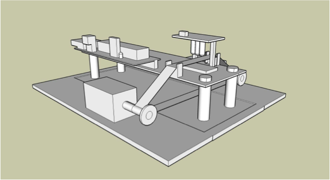 Figure 5e, Hardware 3D Model (5)
 Figure 5f, Hardware 3D Model (6)
The 3D model gave us a clear view of our system hardware and we made some modification of it after discussion. First, the angle of support structures that keeps the script perpendicular to optical sensor is made larger since it provides more stability. Second, the hard paperboard base is cut so as to make one servo movable. The advantages of doing that is once the servo's position can be changed, we can adapt the model design to different lengths of music sheets.
 Figure 6a, Loose position
 Figure 6b, Tight position
Hardware design includes parts listed below:

Figure 7, Station top view
A. Microcontroller
Based on our system requirements, we need 1 SPI (5 pins, SCLK, MISO, MOSI, CS, and Frame Ready) for linear optical array, 1 pin for continuous rotation servo PWM signal, 1 pin for LED light source, 1 UART (2 pins, Tx, Rx) for MIDI message output, 2 pins for MIDI sound effect selector and 4 pins for state machine LED indicators. A total of 15 + 2 (VCC & GND) pins are needed. The microcontroller ATMega1284P that we used in previous lab fits our design, so we will keep on using it as our main control unit.
B. State Machine LED indicators
4 color LEDs are used as the indicator of which of the 4 states that the system is currently in. The 4 states are MaybeNoteOn, NoteOn, MaybeNoteOff, and NoteOff. When state machine goes to one state, the corresponding LED will be turned on.
C. Linear Optical Sensor Array
For our original design, the optical sensor should have sensing region bigger than 1cm to be able to fit in 5-line normal music sheet while still give stable result with noise presented. However, Melexis MLX75306 3rd Generation Linear Optical Array is the biggest optical array we found online that merely meets the requirement and also within our project budget. MLX75306 has 142 customer pixels, 100µm height, 50µm pitch within 7.1mm array length, which means adequate resolution for this project. To accommodate with the length limitation, we chose to use self-defined 3-line music sheet instead of 5-line.
D. Continuous Rotation Servo
To pull the music sheet, we initially considered using the stepper motor. However, the only advantage of stepper motor is high precision, which is not a major issue for our design. Besides, stepper motor consumes more power and requires extra circuit, such as H bridge, to control. The RC (hobby) servo is another available option. RC servos have smaller size and lighter weight compared to stepper motor, so it is a good choice for maintaining the size of hardware system. To make RC servos rotate, we have to change the high duty time of control PWM signal continuously, which will bring unnecessary loading to our system. After considering all the reasons above, we decided to use continuous rotation servo. It has the advantage of RC servo but only fixed high duty time PWM signal is required.
E. MIDI Message Output & MIDI Sound Effect Selectors
MIDI command and data are sent out via UART connection to computer. At computer end, software “hairless MIDI” and “Virtual MIDI Piano Keyboard” are used to synthesis music sound (described in Software section).
2 buttons are connected to change the sound effect of MIDI output by external ISR.
F. LED Light Source
The results of optical array depend on the threshold setting and the light source applied to the music sheet. For easier tuning for the system, we fixed the LED voltage by voltage divider of two resisters and change the threshold of sensor. We tried 3 different kinds of LED for the best result.
First kind of LED is too directional which will cause uneven intensity through out the whole sensing region. The second LED shed light evenly on the sensor but its intensity is too low even for the lowest threshold. Third kind of LED, although, still has problem with uneven intensity, but the problem can be solved by pointing the LED to the line on music script, which will basically cover of interested region.
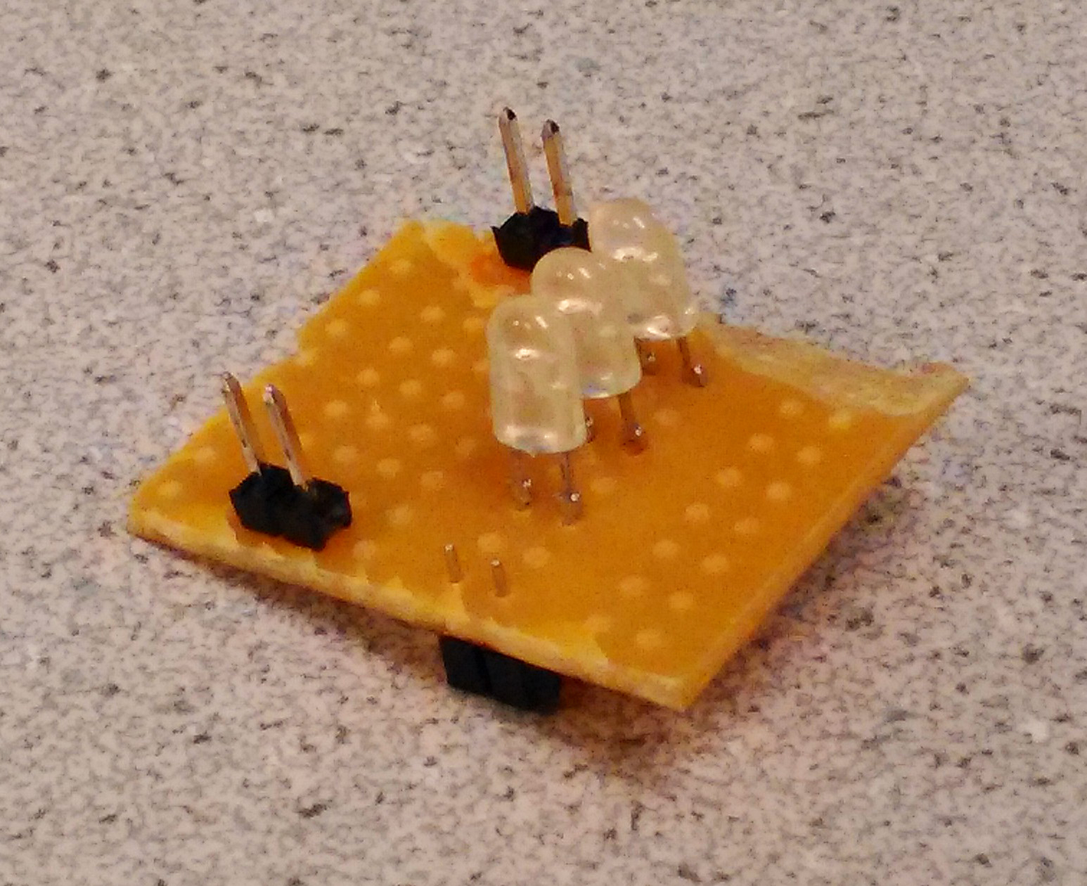 Figure 8a, Yellow LEDs
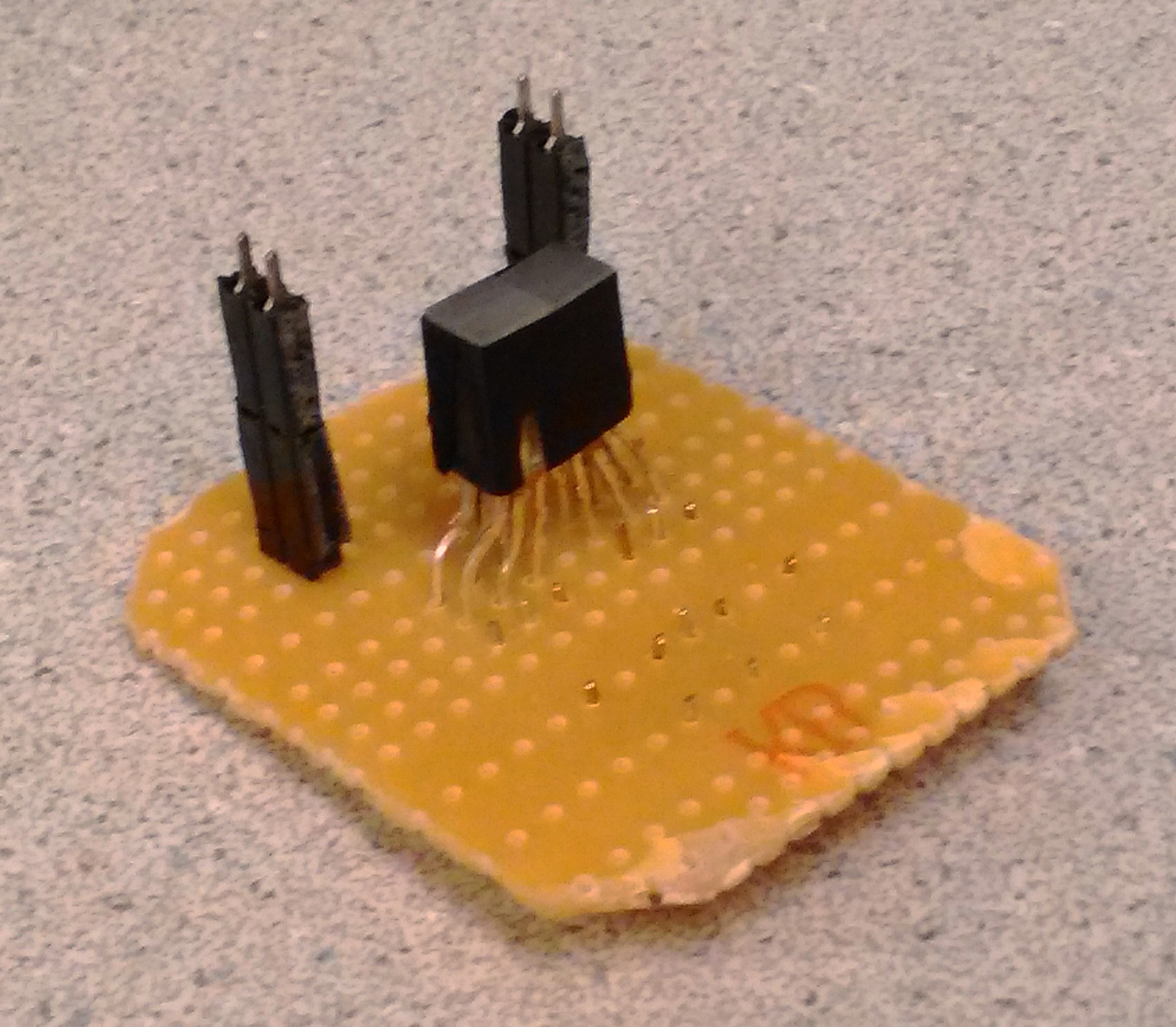 Figure 8b, Square LEDs
 Figure 8c, Red LEDs
Software top
Flow Diagram
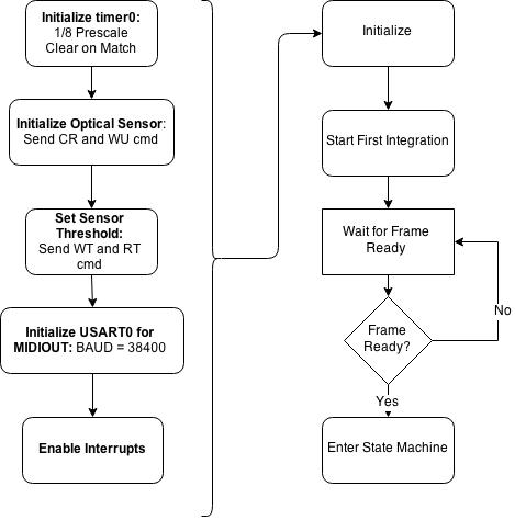
Figure 9: Software flow chart
Function Listing
| Function | Parameter | Description |
|---|---|---|
| void USART_Init(unsigned int baud) | baud – baud rate | Initialize USART0 with baud rate. |
| void USART_Transmit(unsigned char data) | data – data for transmit | Implementation of USART0 communication protocol. |
| void UART1_SPI_init(void) | - | Initializes UART1 in SPIM mode. |
| void USART_Transmit(unsigned char data) | data – data for transmit | Implementation of USART0 communication protocol. |
| uint8_t sendCmd(uint8_t cmd, uint8_t ctrl1, uint8_t ctrl2) | cmd – Command byte ctrl1 – Control byte 1 ctrl2 – Control byte 2 | For sending a single command over SPI to MLX75306. Utilizes UART_SPI function. |
| void sensor_init(void) | - | Initialize MLX75306 with Chip Reset and Wake Up command. |
| void sensor_set_threshold(uint8_t th) | th – threshold for writing | Writes a threshold to MLX75306 and reads a threshold for sanity check. |
| void sensor_readout_1(uint8_t start, uint8_t end) | start – Start pixel end – End pixel | Performs 1 bit read out from MLX75306. |
| void initialize(void) | - | Initialization of all port pins, timer0, registers and interrupts in ATMega1284p |
SPI Protocol for Optical Sensor MLX75306
The MLX75306 linear optical array functions by receiving commands from MCU via SPI protocol. These commands are packaged as 3 bytes of information. The first byte is the command byte specifying the type of operation to be performed on the sensor. The next two bytes are control bytes which usually contains the parameters of the operation. The list of commands used for this project is shown in table below.
| Symbol | Command | Byte 1 | Byte 1 | Byte 1 |
|---|---|---|---|---|
| CR | Chip Reset | 1111 0000 | 0000 0000 | 0000 0000 |
| WU | Wake Up | 1100 0011 | 0000 0000 | 0000 0000 |
| RT | Read Threshold | 1101 1000 | 0000 0000 | 0000 0000 |
| WT | Write Threshold | 11001100 | H3H2H1H0 L3L2L1L0 | 0000 0000 |
| SI | Start Integration | 1011 1000 | T15 .. T8 | T7 .. T0 |
| RO1 | 1 bit Read-Out | 1001 1100 | S7 .. S0 | E7 .. E0 |
To send a command to MLX75306, the CS pin must be first pulled to low. This is because the low level on CS pin and the rising edge of the SCLK determines the start of the internal synchronization counter that starts receiving incoming bits. After the full command (3 bytes) has been sent, CS must be pulled to high for a minimum of 50ns in order to reset the internal synchronization clock for the next input command.
The entire process of sending 3 bytes of command is packaged in the sendCmd() function (refer to function list).
WU and CR Commands
The CR (Chip Reset) command ensures that the sensor is in its initial state just after power up. This resets the internal synchronization clock, which is vital for receiving bits via SPI. The WU (Wake Up) command ensures that the chip is not in sleep mode. In the initialization phase, commands CR and WU must be sent consecutively.
This initialization is handled by sensor_init() function.
WT and CR Commands
The WT (write threshold) command overwrites sensor intensity threshold with our desired value. The first control byte of WT contains the upper threshold while the second control byte contains the lower threshold. Since we used the 1-bit read out mode of the sensor, only the upper threshold is relevant and must be written. Pixels with intensity lower that the upper threshold will return a 0 and pixels with intensity higher than upper threshold will return a 1.
Note that the best threshold for accurate detection of lines on sheet music depends on the type of LED used. For the LEDs used in this project, it was found that a threshold of 0xB0 provides the most stable pixel readout.
The RT (Read Threshold) acts as a sanity check for us to ensure that we have successfully written the desired threshold to the sensor chip with WT. Since SPI protocol in ATMega1284p is full duplex, the threshold is read back to the UDR1 register buffer the moment the second byte in RT command is sent out.
Both these commands are handled by the sensor_set_threshold() function.
SI and RO1 Commands
An SI (start integration) command enables the 142 pixels of the MLX75306 to begin integrating the photocurrents within their respective integration circuit. Control bytes 1 and 2 determine amount of time the photocurrents will be integrated before they are converted to digital output to be ready for read-out. The integration time is calculated as follows:
$$t_{int} = \frac{T_{[15...0]}-4}{f_{RCO}}$$
For our implementation, the 2nd control byte contains 0xFF and f_RCO is 4MHz, indicating that our integration time is 62.8 microseconds. Once integration time expires, the sensor will raise the Frame Ready (FR) signal to indicate that a frame is ready for read out.
The MCU will wait for FR to be raised before sending RO1 (Read Out 1-bit) command to read out the pixel values. The 1st and 2nd control bytes of the RO1 command corresponds to the start and end pixels of the read out. Since we utilized the entire length of the sensor, the control bytes are 0x02 and 0x8E corresponding to the pixel 2 to pixel 143. A total of 30 bytes are readout in a frame for 142 pixels in RO1. The bits corresponding to pixel values in this frame will then be stored in a pixel buffer, which will be parsed for presence of note.
There are no function wrappers for the SI command, but RO1 and the frame handling in MCU are implemented in sensor_readout_1() function. They are called at the end of every cycle of the state machine (~20ms) described below. This ensures that the frame buffer within the MCU is up to date with the latest integrated frame of the optical sensor.
State Machine
Due to the fact that there is a lot of mechanical motion involved, it is difficult to ensure that rotational tape does not shift left or right as it moves across the sensor. It is also difficult to ensure that there are no noisy regions (such as dirt on the tape) that looks like a note onset. The state machine helps to account for these disturbances by “debouncing” a note onset. There are 4 states in the state machine: NoteOff, MaybeNoteOn, NoteOn, and MaybeNoteOff. The full state diagram is shown below:
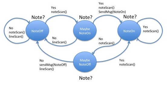
Figure 10: State Machine for debouncing note onset
Two functions are important to the operation of the state machine. The lineScan() function scans through the pixel buffer returned from a sensor read out and updates the lines of the piano roll. The noteScan() function uses the line updated from previous lineScan() to detect anomaly in lines, which may indicate an onset of a note. This function not only returns “true” on the possible indication of a note, but also stores a note number for the note for MIDIOUT if the state machine confirms the note onset.
NoteOff is the initial state that the state machine is in. During initialization phase, a lineScan() must be performed to initialize the positions of the lines. Once in the NoteOff state, noteScan() will be performed to test for presence of note. If noteScan() returns true, the next state will be MaybeNoteOn. Otherwise, it will stay in NoteOff state and perform a lineScan() to update the line positions.
In MaybeNoteOn state, another noteScan() will be performed on the latest sensor read-out to determine if previous noteScan() was just noise. If noteScan() returns true again, state machine will package and send a MIDI noteOn command through USART0 before transitioning to NoteOn state. Otherwise, state machine will update line position through lineScan() and transition to NoteOff state.
In NoteOn state, the state machine will perform a noteScan() to determine if note is still present. If note is no longer present, it will transition to MaybeNoteOff state.
In MaybeNoteOff state, the state machine will perform another noteScan() to determine if previous readout that note is no longer present was an error. If true, state machine will return to NoteOn state. Otherwise, it will send MIDI noteOff command through USART0, perform a lineScan() and transit back to NoteOff state.
USART0 for MIDIOUT
USART0 is used to send MIDI commands to a PC to synthesize sound. Although MIDI traditionally works on 31250 bps, the baud for USART0 is set to 38400bps to interface with the PC. Hairless MIDI is a serial to USB Bridge for MIDI protocols in the computer. The synthesis software used is Virtual MIDI Piano Keyboard (VMPK).
A standard MIDI message is packaged into 2-3 bytes. The first byte is the Status Byte, which defines the MIDI command. This byte is fully specified by the first 4 bits, while the latter 4 bits indicate the channel number. We used channel 1 only in our implementation, which is why the last 4 bits are 0. The next two bytes that follow are the data bytes containing the parameters of the command. The MIDI messages used in our implementation are listed below.
| Status Byte | Data Byte 1 | Data Byte 2 | Description |
|---|---|---|---|
| 1000 0000 | 0nnn nnnn | 0vvv vvvv | Note off event on channel 1. Data Byte 1 contains the note number. Data Byte 2 contains velocity |
| 1001 0000 | 0nnn nnnn | 0vvv vvvv | Note on event on channel 1. Data Byte 1 contains the note number. Data Byte 2 contains velocity |
| 1100 0000 | 0ppp pppp | - | Program Change on channel 1. Data Byte 1 contains the program number. |
MIDI number of scanned notes is determined by noteScan() function in the state machine and the communication protocol is handled by the send_MIDI_msg() function. Velocity of each command is standardized to 127 for audibility.
Timer 0 for Servo PWM and State Machine Cycle
In order to move the sheet across the sensor, the continuous rotational servo is used. For the parallax 900-00008 continuous rotational servos, a voltage signal of 1.3ms to 1.5ms rotates it clockwise while 1.5ms to 1.7ms correspond to anti-clockwise rotation. A 5V voltage held for 1.5ms corresponds to no rotation. The voltage must be held low for at least 20ms in between each voltage high regions.
The timing for voltage control is implemented in timer0’s compare match mode. The prescale is set to 2MHz and the output compare register (OCR) is set to trigger compare match ISR every 20 clock ticks. This gives us a resolution of 0.01ms for every interrupt and a millisecond counter incremented in timer0’s compare match ISR.
For our purposes, we raise the voltage to the servo for 148 counts, corresponding to 14.8ms, before pulling the voltage down for 200 counters of the millisecond counter (20ms). This gives us a slow enough rotational speed for counting.
INT2 for Program Change
An extra feature that was implemented was a push button to trigger a MIDI Program Change command. This allows for selection of music timbre on VMPK during sound synthesis.
External Software
For the sound output, we used VMPK to generate a collection of 127 synthesized sounds. MIDI bytes are packaged using the UART protocol and sent out through UART0. Hairless MIDI receives the bytes and converts it to USB signal. The USB driver on the PC will then port the signal to VMPK for synthesis.
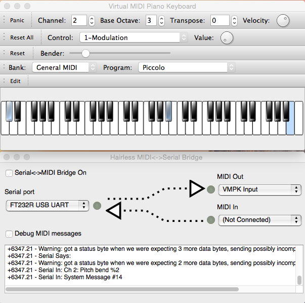
Figure 11, Hairless MIDI (bottom) and VMPK (top)
Results top
Pulse Width Modulation
The Parallax Continuous Rotation Servo is controlled through pulse width modulation. Rotational speed and direction are controlled by the duration of a high pulse, which should be in the 1.3–1.7 ms range. In addition, the servo needs a 20 ms pause between pulses that means the period should around 21.3ms-21.7ms.
When the duration of a high pulse is in the 1.3 – 1.5 ms, the servo will rotate in the clockwise direction. Otherwise, if the pulse width is in the 1.5 – 1.7 ms, the servo will rotate in the counter-clockwise direction.
In our project, we expect the servo rotate in the counter-clockwise direction, which means the pulse width should between 1.5-1.7ms. The oscilloscope screen captures are shown below and those pictures clearly show our servo rotate in the counter-clockwise (1.6ms).
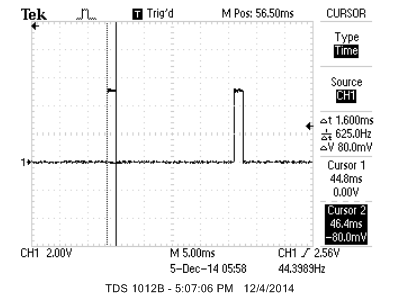 Figure 12a, The pulse width is 1.6ms
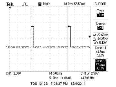 Figure 12b, PWM period 22.0ms
SPI communication
In our design, the MCU sends the requests (command) to MLX75306 sensor through SPI. The following table and figures show the normal command we send to sensor and the corresponding oscilloscope screen captures.
| Symbol | Command Description | Control Byte |
|---|---|---|
| CR | Chip Reset | 1111 0000 |
| WU | Wake Up | 1100 0011 |
| RT | Read Threshold | 1101 1000 |
| WT | Write Threshold | 11001100 |
| SI | Start Integration | 1011 1000 |
| RO1 | 1 bit Read-Out | 1001 1100 |
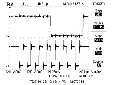 Figure 13, Chip Reset
 Figure 14, Wake Up
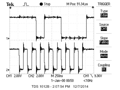 Figure 15, Read Threshold
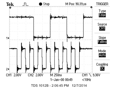 Figure 16, Write Threshold
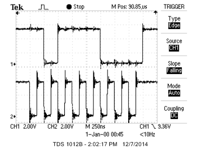 Figure 17, Start Integration
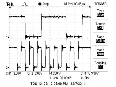 Figure 18, 1 bit Read-Out
UART
Visual Display on Putty
Apart from playing the note with MIDI, we also implemented a sensor testing code to see what is the actual “view” the sensor detected. We achieved this by using putty to display all 142 pixels. The blank music sheet with only 3 lines and 5 lines are shown below, ‘_’ indicates black pixel and ‘%’ indicates clear pixel.
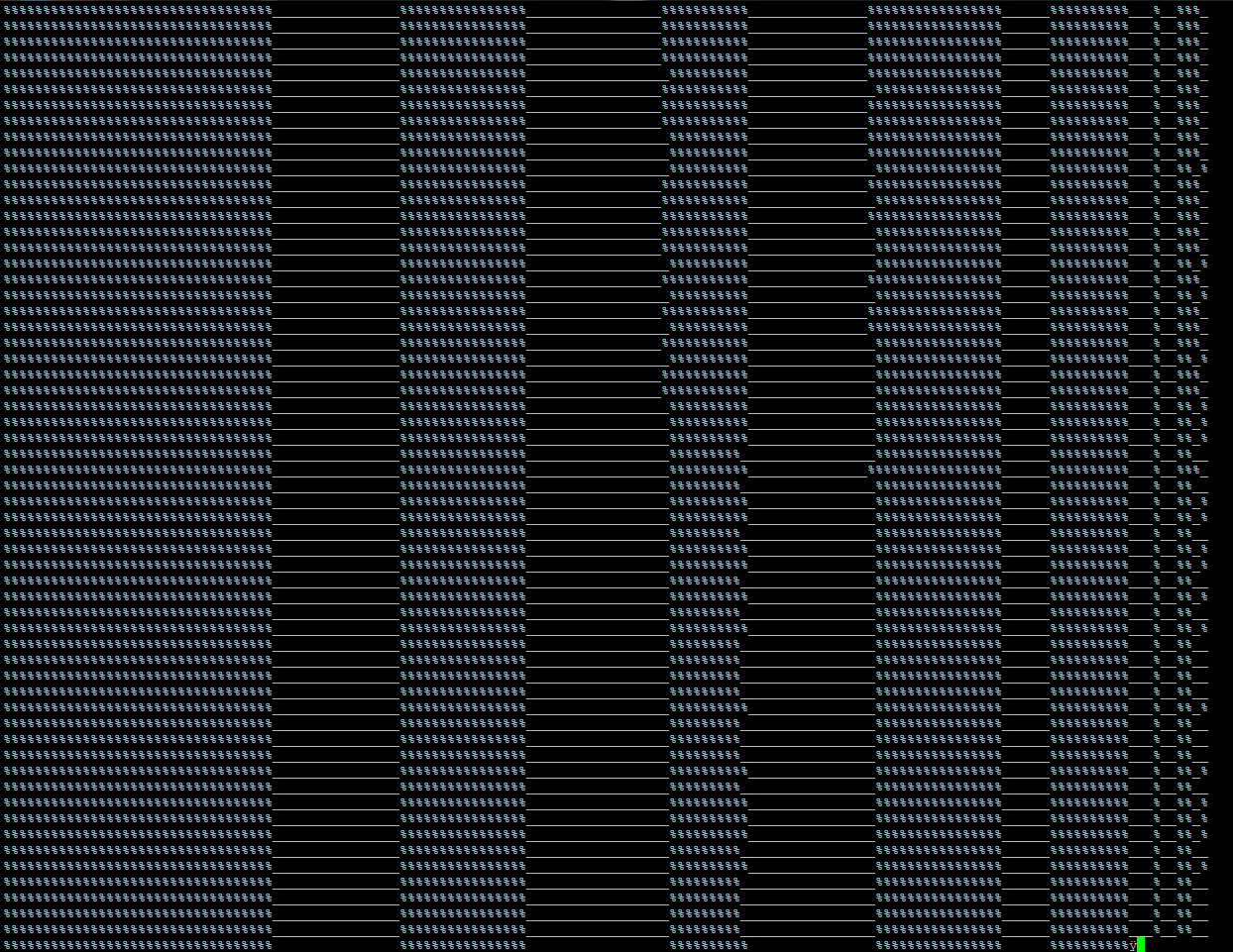 Figure 19, Blank music sheet with 5 lines
 Figure 20, Blank music sheet with 3 lines
The following figures show the line with notes on it and what is the actual music sheet looks like:

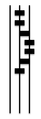
Figure 21, Notes scanning result
Signal Received from UART on Oscilloscope
We also use oscilloscope to illustrate we receive the correct signal. The first figure indicates we receive ‘_’ with hex number 5F5F (0101 1111 0101 1111) with extra starting bits, and the second figure shows we receive ‘%’ with the hex number 25 (0010 0101). What is worth a mention is that the number displayed on the oscilloscope is in the reverse order.
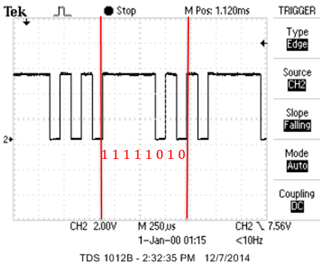 Figure 22, Receive hex number 5F
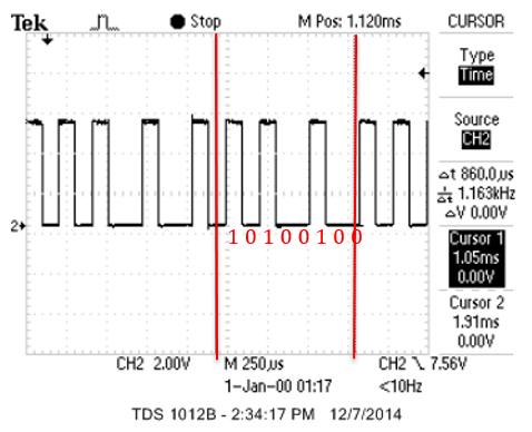 Figure 23, Receive hex number 25
MIDI verification (number displayed in reverse order)
| Meaning | Decimal Number | Binary Number |
|---|---|---|
| Note | 62 | 0011 1100 |
| Velocity | 127 | 0111 1111 |
| Channel 1 Note Off | 128 | 0000 0001 |
| Channel 1 Note On | 144 | 0000 1001 |
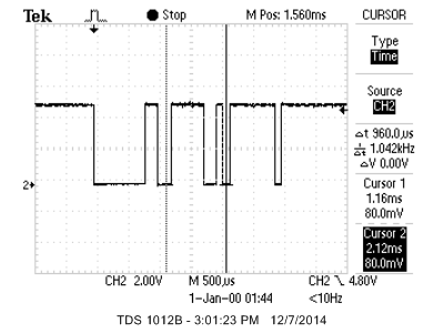 Figure 24, Channel 1 Note 62 Off
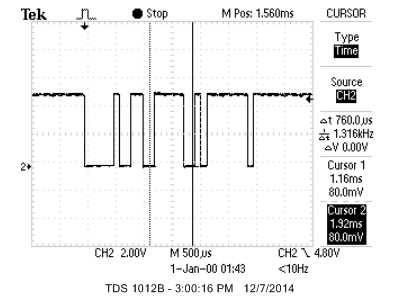 Figure 25, Channel 1 Note 62 On
Real Music Test
A. Standard Test (quarter note and half note)

Figure 26, Standard Test (quarter note and half note)
B. Jingle Bell
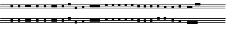
Figure 27, Jingle Bell
C. Ode to Joy

Figure 28, Ode to Joy
D. Silent Night

Figure 29, Silent Night
Videos
Accuracy
| Scientific Name | # of Scan | # of Correct Play | Accuracy (%) | |
|---|---|---|---|---|
| Jingle Bell | C4 | 3 | 3 | 100 |
| D4 | 6 | 6 | 100 | |
| E4 | 23 | 23 | 100 | |
| F4 | 10 | 10 | 100 | |
| G4 | 5 | 5 | 100 | |
| Ode to Joy | C4 | 11 | 11 | 100 |
| D4 | 16 | 16 | 100 | |
| E4 | 17 | 17 | 100 | |
| F4 | 8 | 8 | 100 | |
| G4 | 6 | 6 | 100 | |
| Silent Night | D4 | 4 | 1 | 25 |
| F4 | 9 | 6 | 66.7 | |
| G4 | 12 | 9 | 75 | |
| A4 | 3 | 3 | 100 | |
| B4 | 3 | 2 | 66.7 | |
| C5 | 2 | 1 | 50 |
Safety and Usability
Safety is always treated as a standard to determine whether a product can be widely used. In order to avoid any potential risks of the sheet music reader, we build an unmanned rotational servo to pass the music sheet under the senor with a constant speed. Due to the low reading speed of this product, user might need to hold the music sheet for a long time, which will make them feel uncomfortable. The unmanned music sheet conveyor would overcome this problem with its automatic transport feature. Additionally, more and more people like composing music at their spare time. However, most of amateurs would not spend a lot of money to purchase a professional composing instrument, they just need a simple and cheap product to help them convert their music notation to the corresponding sound. Our product meets this mark demand with a low price and easy operating system.
Conclusions top
Results Summary
The result of the work is very close to our goal, which is a five-line music sheet scanner. When performing five-line scanning, the average accuracy is around 60 percent which still allows the listeners to distinguish the song from others. For three-line scanning, the performance is very impressive. All notes are correctly detected and the length of each note is also mapped to corresponding duration of sound.
After experiments, the results shows that the accuracy is highly depending on several point:
- The distribution of light intensity
- The stability of music sheet roller
- The transparency of music sheet
lighting condition greatly effect the sensor's capability of scanning. The tuning of light intensity and sensor integration threshold is quite sensitive. Our solution is fixing the threshold and tune the LED cross voltage. The reason is that threshold can only be changed discretely, which may lead to huge differences in results by 1 value variation. The distance between LEDs and sensor not only affects the intensity that sensor received but also the distribution of light. Therefore, it is also important that the distance should be variable.
Since the sensor working area is about 7 mm wide, the stability of music sheet roller become a big issue. Although many works has been done, such as supports next to the sensor, the hot glue applied on servo to get greater friction, carefully aligning of two servos, to make it as still as possible, the system sometimes still makes error due to miss alignment of sensor and sheets
At the beginning of our project, music sheets are printed on regular white printing paper. After several experiments, we found out that for sensor to be able to detect, the intensity of light source has to be set relatively high value. In this case, the light goes through the region, where notes and lines are printed, as well. As a result, causing the accuracy to drop. The solution is that we print music sheets on transparent slide by laser printer. The outcome has great precision of scanning and also better durability of sheets.
Conformance to Standards
From the oscilloscope screen capture shown in the results section, it can be seen that we followed the SPI and UART communication protocols very closely. Musical data was also packaged in conformation with MIDI standard and this was able to be decoded by external MIDI synthesizer. However, we did not adhere to the standard MIDI baud rate of 31250 bps since communication with PC requires 38400bps for historical reasons.
Legal and Intellectual Property Considerations
Music, both in printed form and recorded form, may be copyright protected. In this project, the songs that were converted to printed sheet notations are “Ode to Joy”, “Jingle Bells” and “Silent Night”. These are general public songs and are no longer copyright protected. “Ode to Joy”, first composed by Ludwig Van Beethoven as symphony no. 9, is no longer copyright protected as it is more than 95 years since the composer’s death.
As the entire hardware was made from a novel design, there are no infringement of intellectual property. Other than the AVR standard library, no external libraries were used in the implementation of our source code. All functions for state machine and decoding were written from scratch. The UART and SPIM communication functions for transmit and receive of data byte were provided ATMega1284p datasheet.
The idea of the state machine was first introduced in ECE4760 lab2 for debouncing mechanical button press. The adaptation of the state machine for de-noising note onset in our musical scanner is a novel idea.
Future Work
The design of this musical sensor can be improved in several ways to bring it steps closer to reading actual sheet music notation:
- Using 2 calibrated MLX75306 optical sensors to sense 5 staff sheet music accurately.
- Incorporate computer vision techniques to detect stems of music notes to determine timing.
- Implementing multiple note detection for playing chords.
Appendices top
A. Program Listing
B. Schematics

Figure 30, hardware schematic
C. Parts List and Costs
| Item | Vendor | Unit Price | Quantity | Total Cost | Comment |
|---|---|---|---|---|---|
| Continuous rotation servo | Digi-key | $14 | 2 | $28 | 900-00008 |
| Linear optical array | Melexis | $15 | 1 | $15 | MLX75306, Sample |
| Solder board (6 inch) | Lab Stock | $2.5 | 1 | $2.5 | |
| Small solder board | Lab Stock | $1 | 1 | $1 | |
| Large Solder Board | Lab Stock | $2.50 | 2 | $5 | AVR microcontroller | Lab Stock | $5 | 1 | $5 | ATMega1284P | Power Suplly | Lab Stock | $5 | 3 | $15 |
| RS232 connector | Lab Stock | $1 | 1 | $1 | |
| SOIC carrier | Lab Stock | $1 | 1 | $1 | |
| DIP socket | Lab Stock | $0.5 | 1 | $0.5 | |
| 9V Battery | Target | $1.57 | 2 | $3.14 | |
| Sand paper roll | Lab Stock | $1 | 2 | $2 | |
| Small circle black board | Lab Stock | $1 | 3 | $3 | |
| Header pin | Lab Stock | $0.05 | 57 | $2.85 | |
| Switch | Lab Stock | $0 | 1 | $0 | |
| Capacitor | Lab Stock | $0 | 2 | $0 | |
| Resister | Lab Stock | $0 | 5 | $0 | |
| Diode | Lab Stock | $0 | 9 | $0 | |
| Wire | Lab Stock | $0 | 4' | $0 | |
| Paperboard | Lab Stock | $0 | 1' x 1' | $0 | |
| TOTAL | $76.85 |
References top
Acknowledgements top
We thank Professor Bruce Land for his the great lecture he taught and the help in lab, and the TAs for all the debugging hours that they spent with us.
We also appreciate Melexis for giving us sample component of linear optical array, which is the most important part in our project.