Piano Sight-Reading Assistant
ECE 4760 Final Project, Fall '14
Victor Fei (vf63), Olivia Gustafson (org5), and José Villegas (jfv33)
Introduction
Our project connects a piano-like handmade keyboard to a microcontroller to monitor input and match it to a pre-coded song that displays on an LCD screen in the form of properly-formatted sheet music.
Design
Interface | Keyboard/Glove Design | Connections | Communication | Sound | Difficulties & ChoicesWith the advent of musical video games such as Guitar Hero and Rock Band, we thought it would be a great project to take the core idea of these games and make into something useful for the intermediate to advanced musician. Our design shows sheet music on a TV and compares the notes to keyboard input to see if the user is playing the music correctly. If the user presses the correct notes at the correct time, (s)he gains points. If the user plays incorrectly, (s)he loses points.
Interface Design
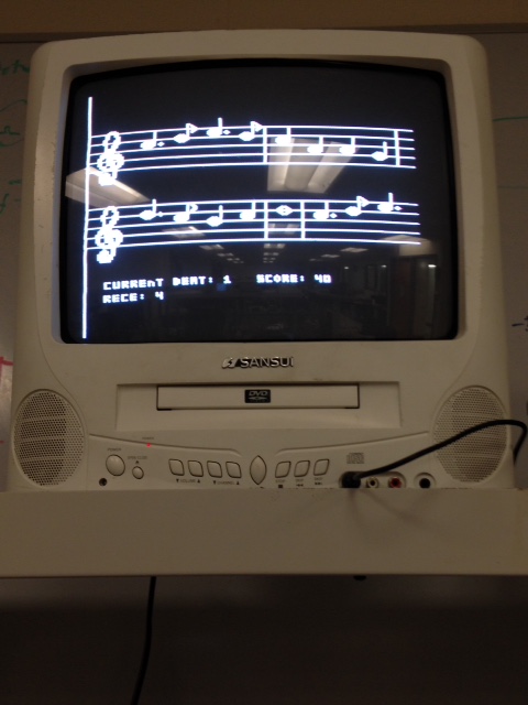
The interface consists solely of one microcontroller (ATMEGA 1284p) connected to a TV screen via NTSC. It is connected to the keyboard via serial connection to the other 1284p that we are using. The interface is responsible for displaying music, updating music, and calculating score based on keyboard input via serial connection.
The sheet music is displayed in the following fashion:
- Note structures are created in order for the entire song.
- Notes are placed sequentially until their total value is more than a full measure.
- A measure (bar) line is placed and the beat is reset
- Numbers 2 and 3 are repeated until the line is full.
- A new line is started and steps 2 through 4 are repeated until the page is full (or the last note is drawn).
- Staff lines and clefs are drawn to complete the page.
- The display is halted until the user plays the entire page.
The interface was designed using a mapping of bit values - each kind of note was essentially drawn as a square of 0s and 1s - 1 being a white pixel and 0 being a black pixel. In this fashion, all notes and clefs were drawn.
Keyboard and Glove Design
The keyboard is comprised of keys that can play up to two-octaves. Our range is from Middle C (C4) to B5.
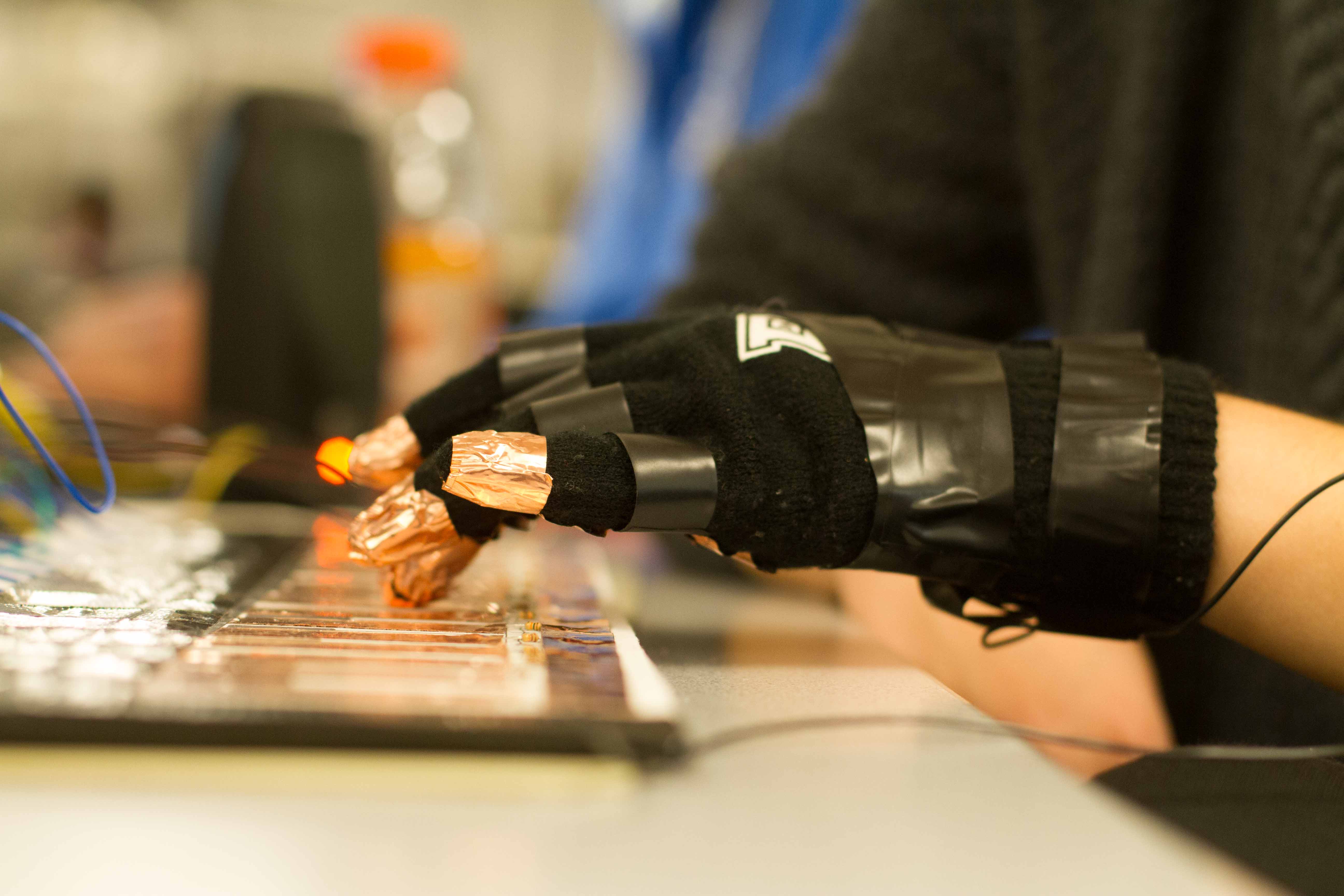
Our keyboard does not support sharps or flats. Keys are surface mounted on the keyboard. To play on the keyboard, the user needs to wear our glove.
The keys of the keyboard are made of copper strips and are charged to 5V. When the user plays on the keyboard,
the glove grounds the 5V charged key and the microcontroller detects this change in key's voltage
to know if a key is pressed.
Keyboard Circuit
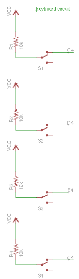
The keyboard circuit picture only shows keys C4 to F4. For each key is charged to Vcc (5V). When a key is pressed with the glove, the glove grounds the key. The 10k pull-up resistor of each key ensures that when one key is pressed and grounded, the other keys remain charged. The circuit of the glove is just wires connected to grounds.
Keyboard and Microcontroller Interface
The keyboard contains up to 14 keys, and the microcontroller needs to be able to detect the status of each key in real time. Directly wiring each key to each port on the microcontroller would involve 14 distinct connections directly to microcontroller. This would create massive number of wires directly to the microcontroller. To simplify the hardware interface directly to the microcontroller, we decided to use two 8 bit 74HC166 Parallel-In-Serial-Out (PISO) shift register to sample parallel inputs from the keyboard and generate a serial output to microcontroller.
Each PISO shift register is capable of receiving 8 inputs and generate 1 serial output. Two shift registers is used to sample 14 inputs, and two serial output wires are used to output to microcontroller.
How PISO shift registers work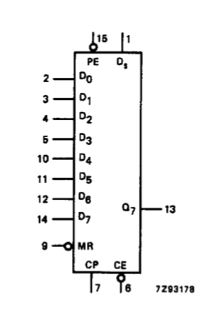
Parallel in refers to that the shift register can read all parallel inputs from D0 to D7 in to the shift register. At rising clock edge when PE, parallel enable input (active-low), becomes low, new values are read. And at each subsequent rising clock edge, a value is shifted out at Q7 beginning with D7. So at the first rising edge, we get the value of D7. At the second rising edge, we get the value of D6. At each rising clock edge, we sample the data at the Q7 port.
Sampling Rate PWM Clock and Parallel Enable Input Signals
We used the microcontroller to generate both the clock signal and the parallel enable input signals for the microcontroller.
When we built the piano, we assumed that the fastest speed a person strikes keys is less than 1/10th of a second. So we decided to sample 10 inputs per sec. In Our design is able to sample all keys per 100ms (1s/10 = 0.1 sec). Since each shift register has 8 inputs, we need 8 cycles to serially shift out all the keys. Thus total of 8 cycles is needed. Readings of the shifted out values also takes place at each rising clock edge, and are done in parallel with the register shifting to shift values out. Writes to shift registers occur at rising clock edge and when PE is pulled low. We used timer2 to generate the PWM signal for so we need 8x2=16 ticks. 100ms/16 = 6.25 ms. so the PWM must run with a period of 6.25ms = 160 Hz.
To achieve 160 Hz clock cycle we used Clear Timer on Capture mode. We also toggle the output of the PWM. We set OCR2A to be 96, and when OCR2A overflows it clears and becomes zero. We set the timer's prescalar to be 1024. So according to the equation below, we obtain 160 Hz for the clock PWM signal.
16e6 / (1024 * OCR2A) = 160 Hz
Communication Between Two Microcontrollers
We used two microcontrollers in our project. Microcontroller 1 samples the keyboard input and generates the sound using Karplus-Strong algorith. Microcontroller 2 generates the video and keeps track of how well the player is playing the given song. Because of this, we needed to communicate the information of the keys that are pressed between the two microcontrollers. Microcontroller 1 acts as the sender and microcontroller 2 acts as the receiver. Neither can microcontroller 2 cannot send data, nor microcontroller 1 receive any data. Thus, the communication is uni-directional.
UART
We used the built in UART serial communication to send and receive data on both microcontrollers. The sender (microcontroller 1) uses UART port0 Tx to send data to the receiver (microcontroller 2)'s UART port1 Rx. The UDRn register in the UART port both stores received data and stores data that is about to send. The sender uses UDR0 to send data, where as on the receiver's end data arrives in UDR1. The baud rate of the UART is set to 57600, so that the receiver's end can keep up speed with the speed of video generation. Any speed slower than that rate will cause significant lag in the video generation which affects the game play. To coordinate communication between the two microcontrollers we had different options. More, but we settled on the UART because UART has already been tested to be functional.
Data Packets
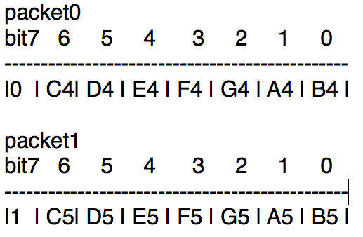
The entire key press status of the keyboard is contained in two packets. Each UART packet contains 8 bits or a char. We used a single bit to represent the status of each key on the keyboard. Since there are 14 functioning keys on the keyboard we would need at least 14 bits to represent the entire keyboard. We split the 14 status bits of the keyboard in half and each packet contains 7 keys.
The most significant bit of each packet is the packet header. Packet0's packet header is set to 0, to indicates that there is still more packets to follow. Packet1's packet header is set to 1 to indicate that it is the last packet and no more packet after it. When the receiver receives each respective packet, it would then know the order of the packets. Bit 6 of packet0 represents the left most key on the keyboard (C4), and bit 0 of packet1 represents the last key on the keyboard (B5). Thus, our packets use Big-Endian format to represent the key.
Sound Generation
Karplus-Strong Algorithm
The Karplus-Strong Algorithm is a method for physical string modeling. The algorithm feeds a delay line with white noise, then low pass filters the shifted output of the delay line and adds it back into itself. If we want to generate a tone of known frequency, we can use the following equation to determine the appropriate length of the delay line:
delay length = frequency of sampling / frequency of tone
This method is straightforward to implement in software and produces realistic tones.
Implementation
Karplus-Strong was implemented in the ATMEGA1284P.
An emulated circular buffer and fractional delay unit implement the delay line. The fractional delay unit must capture the fractional part of the delay line length because the buffer must have an integer length.
The length of the buffer plus the length of the fractional delay correspond to the length of the delay line in the following manner:
delay length = delay (integer part) + delay (fractional part)
Thus,
delay (fractional) = fractional(frequency sampling/frequency tone) and
length buffer = int(frequency sampling / frequency tone)
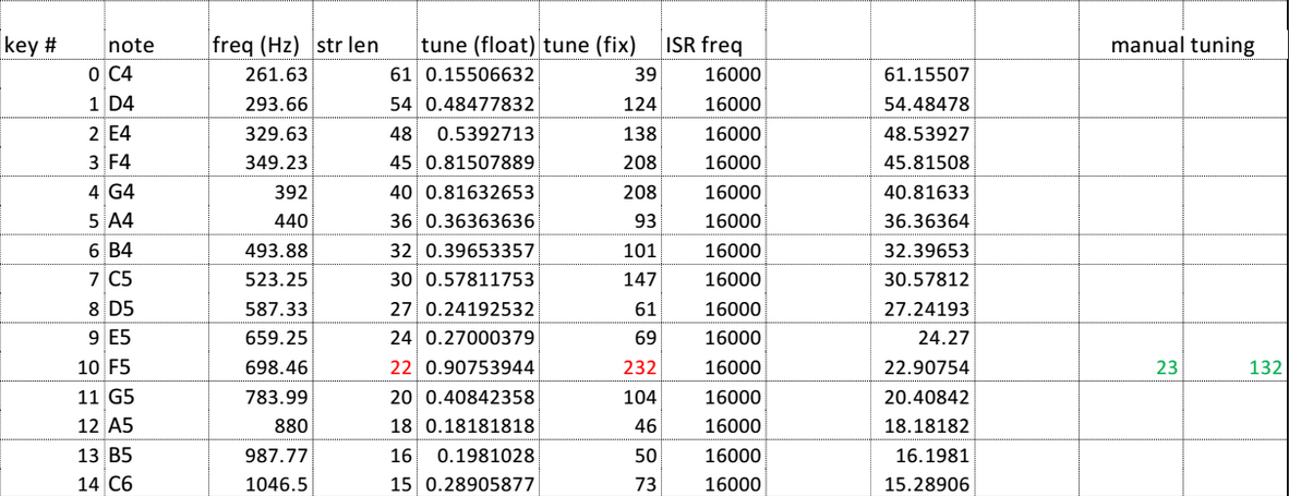
Thus we can set set the buffer length and the fractional delay to produce a tone of desired frequency. The table in the Appendix lists the buffer length and fractional delay for each supported note. The fractional delay is shown in both fractional notation and in 8.8 fixed point format. Fixed point format was used in the program because operations on fixed point operands are much faster than operations on floating point operands.

As can be seen in the above image, the circular buffer is embedded within a larger array, thus the buffer’s length can change dynamically. The fractional delay can also change dynamically. Thus, tones of different frequencies can be generated.
The image below shows the Karplus-Strong unit that was implemented in this project. The figure also shows the peripherals that interact with the KS unit. These peripherals include the PWM, SPEAKER, and INTERFACE.

The KS unit was implemented within a C program. The program consists of two sections: an ISR and an main while loop. Both sections are periodic. The main while loop has a period of 50ms. Its purpose is to execute a debounced read of the key array every 50ms. The ISR executes at a frequency of 16KHz. Its purpose is to update the state of the circular buffer. Essentially, this means doing the operations show in the below image and then incrementing the pointers. When a pointer a reaches the last element of the buffer, it wraps back around to the first element.

When a new key is pressed, in the next execution of the ISR, the ISR must change the buffer length and fractional delay so that the new tone can be generated. To do this the ISR references two arrays. The ISR must also energize the entire buffer with white noise by populating each element with uniformly random values. In subsequent executions of the ISR, the buffer outputs high energy samples to the PWM, which are heard as the tone of desired frequency. While the key is pressed down, the ISR decreases the damping so that the tone is sustained for a longer period as would happen in a real Piano. When the key is released, the damping goes back to the normal level. In this case, as the system progresses, the damping drives the energy of the buffer back down to zero and no tone can be heard again. until we once again press a Piano key.
Design Difficulties and Choices
Keyboard
Initially, we were considering modifying a commercial piano keyboard by adding sensors at the bottom of the keys to detect key press. However, after closely inspecting the commercial piano keyboard in lab, we realized that modifying and debugging the keyboard would be onerous and our time was running short. It was much faster to build our own keyboard from scratch. We were very content with the results of our keyboard and glove. The copper-strip coated glove also adds a steam-punk feeling to the entire project.
Microcontroller Communications
We initially planned on using a single microcontroller to achieve keyboard reading, sound generation, and video interface. However, the video generation has a very fast speed that placing sound generation and key press reading would distort the video signal. Additionally, adding other interrupt service routines for keyboard reading or sound generation would interfere with the interrupt service routine of the video and creating a very flickering video. Due to these reasons, we decided to use a separate microcontroller to handle the sound and key inputs and using UART to send the status of the keys to the second microcontroller.
Data Packet Frame Order
Since two packets are sent and each packet represents one half of the keyboard, it is important to get the order of the packets correct. We initially did not include and packet headers to signify the order of the packets, because we assumed that if a packet gets sent first it will also get received first. However, in reality, the first packet that gets sent may not always be received as the first packet. To solve this problem, we made the most significant bit of each packet to be the packet header which signifies the order that these packets should be received.
Song choice and Multiple Inputs
Ideally, our program would be able to play multiple songs and let the user choose between them. While we knew we didn't have enough time to create a system that could read files and parse them, we explored the possibility of using a MIDI-style encoding to read music files. However, it became clear that our effort was better spent improving other aspects of our project and implementing a simpler way to encode the music.
Another tradeoff we made because of timing constraints was limiting the program to one input at a time. In this fashion, the user can only hit one note at a time, so the music is restricted to simple melodies. This can be easily extended in the future to allow for a more robust system consistent with the needs of a pianist.
Design Methodology
An incremental and test-driven design methodology was used to extend the provided code. We used Professor Bruce Land’s Karplus-Strong code as a jumping off point. We added some functionality to the code provided by Professor Bruce Land. BL One Karplus-Strong unit means that we can play one key at a time. BL One string per note. BL Two state key press debouncer. BL Fixed point multiplication. + Dynamically decreasing the damping, while a Piano key is held down, means that a note can be sustained. + Dynamically changing the buffer length and fractional delay means that we can play many tones using only one Karplus-Strong unit. Legend: BL Already implemented by Professor Bruce Land + Added functionality
Results
Speed/Accuracy | Safety | UsabilitySpeed and Accuracy
Screen Refresh Rate and Game Logic
The existing code we borrowed from Prof. Bruce Land used NTSC protocols to generate visuals on a screen with an exact 60 Hz refresh rate. Any logic for the displays or score generation are computed between screen refreshes, so the code must be very straightforward and as quick as possible. We found that the game logic ran quickly enough to make the video work seamlessly. However, once we added the UART, our code took two refreshes to complete computation. This was a fixable (though undesirable) affect - to negate it, we simply made our music play twice as fast.
On the user's end, timing is only an issue when pressing keys. The user's goal is to press the correct key at the correct time, and so it is important on our end to be strict about timing but also allow for natural human imprecision. As such, we allow for about a quarter-second window before and after the expected key press.
Keyboard Sampling Rate
As mentioned in the design section, the PWM clock signal is at 160 Hz, which gives the ability to sample 10 changes in key press per second. In other words, every 0.1 second we detect the status of all the keys. We chose this speed because we assumed that a person may not be able to press the key more than 10 times per second. When we tested our result, we found that we were able to get immediate response of the key press with no observable delay. Thus, 10 samples per second for key press is a feasible sampling rate.
Sound Generation
Our Piano has support for 14 notes. The figure below shows the measured FFT for three different keys: the lowest frequency key C4, A4, and the highest frequency key, B5. Notice that all tones exhibit harmonics.


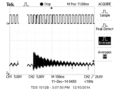
The table below summarizes these measurements, lists the known frequencies of the three keys, and gives the error. Some of this error is introduced by the 8.8 point fixed format representation. However, for entertainment purposes, we believe the error is acceptable. The figure below shows the effect of damping. As you can see, this particular tone, A4, decays in about 3 divs which corresponds to about 300ms.
Microcontroller Communications
The speed that UART sends and receives data is at 57600 bits per second. This speed is much faster than the typical baud rate of 9600. The reason we implemented this high baud rate is because we wanted to match the speed of the video generation. In our original implementation, the UART baud rate is 9600 but it caused significant delays in the execution of video generation. By increasing the baud rate to 57600, the UART receiver code can keep up speed with the speed of video generation.
Safety
Gloves and Keyboard Apparatus
The keyboard and the glove is safe for the user. Although charged, the keyboard only goes up to 5V, which does not create any hazard for users.
Usability
Our product is very intuitive for the pianist who is familiar with basic technology, who is, coincidentally, our intended user. The keyboard is laid out the same way a piano is, and the feedback is relatively clear - if a note is played correctly, the score increases immediately by 10 points. What might make it difficult for the average pianist are the slightly wider keys and the lack of auditory tempo feedback. Currently, the beat is displayed on the screen, which makes it difficult to monitor while also reading the music on the screen.
If the program is used by an untargeted user, it will likely not be enjoyable (though the program will still work as intended). It can take months for new musicians to learn to read music, and many more months to learn to sight-read it. While this is indeed a sight-reading assistant, it would be incredibly difficult for the new pianist to use it and find it useful.
Conclusions
Success | Standards | Considerations | ImprovementsSuccess of the Project
The final project was a great success. We were able to create a keyboard comprised of keys that can play up to two-octaves. The real time music sheet on the screen and score system provides the user a real time feedback of his or her performance.
Conformity to Standards
Our keyboard is constructed very similarly to a traditional piano. The keys are in the standard fashion, but currently only span two octaves. In other traditional musical fashion, the music is displayed on staves with a treble clef. This kind of musical display is standard among all musicians, and the treble clef is often preferred by pianists.
Legal and Ethical Considerations
The aim of this product is similar to popular video games like Guitar Hero and Rock Band. However, our product is very different in two ways: first, it uses a realistic piano keyboard, and second, it displays music in a sheet music (traditional) fashion.
Possible Improvements
User Display Interface
While our product is fully functional, there are clearly some improvements that can be made. Most noticeably, our program currently only plays one song (Cornell's Alma Mater). One improvement that could be made is to support reading MIDI files - perhaps by SD card - and allowing the user to choose between the MIDI files on the SD card. Secondly, implementing support for multiple-note input and multiple-note display would make the program much more robust. Currently, the keyboard detects multiple inputs, but the sound generation and video game logic only support one-hot inputs.
The music display can also be improved in a few ways. Currently, sharps and flats aren't supported, which means only music in C major or A minor can be displayed. In addition, there is no feedback when a wrong note is played - the score is the only feedback from input that is visible on the display. Having some way of highlighting the current note you're supposed to be playing, or some feedback telling you what note you pressed incorrectly, would be a helpful improvement to the system.
Keyboard
Our keyboard and gloves are very robust. The only downside is the contact surface of the glove is not smooth. The ripples of the copper tips of the glove sometimes trigger multiple key press on the keyboard. The double key press issue could not be solved by conventional key press debouncing. An area of significant improvement would be to smooth out the surface of the glove so to avoid double key strikes.
Our keyboard and gloves are very robust. The only downside is the contact surface of the glove is not smooth. The ripples of the copper tips of the glove sometimes trigger multiple key press on the keyboard. The double key press issue could not be solved by conventional key press debouncing. An area of significant improvement would be to smooth out the surface of the glove so to avoid double key strikes.
Since the gloves make the user play the keyboard differently than on an actual piano bare-hand. A potential improvement would be to build a keyboard that does not require wearing gloves, which would be an attempt to simulate the condition of playing on a real piano. This would involve more complicated sensor systems on the keyboard to detect the press of the finger. Additionally, wearing the glove to play the piano is cool. It gives a steam-punk feeling to the entire system.
Sound Generation
Play more than one key simultaneously. We would need one KS units for each key that we wanted to play simultaneously. Each KS unit runs inside the ISR; therefore, having multiple KS units may lead to very long ISR that do not meet the timing constraints. Two or three strings per note. This would add realism; however, it would also make the ISR longer because we would also need one KS unit per string. Better debouncing. A larger state debouncer would reduce the number of false double presses.
Appendix
Code
Video display codeUART receiver C include file
UART receiver H include file
Keyboard and Sound code
UART C include file
UART H include file
Block Diagram

Table of Note Configurations
Costs
Two ATmega 1284p’s - $10Two 9V power supplies - $10
One LCD TV screen - $5
Keyboard - $0 (made from cardboard and tape)
References
Code was built off of NTSC and Karplus Strong code made available on the ECE 4760 website (people.ece.cornell.edu/land/courses/ece4760).