2-Player Tetris
By: Ryan Smith (rcs258)
· Brief overview
I have created a 2-player Tetris game with one NTSC TV, a
Mega 1284 microcontroller, 2 keypads, and many lines of C code
· Reasoning Behind Project
After completing the video game lab in class, I realized I
wanted to make my own video game using the NTSC TV. I wanted to make a 2 player Tetris game
mostly because it’s one of my favorite video games. Also because while browsing the lab projects
and seeing that while Tetris has been implemented, there was no 2 player Tetris
game that I came across. I wanted to
implement gray scale into the project, but didn’t have the time as the software
took an incredible amount of time.

High Level Design
The project
consisted of the hardware design and the software design. The hardware design was fairly simple while
the software design included thousands of lines of code.
The hardware
design was very similar to the hardware for the video game lab (lab 3). I had a 3 resistor DAC that modified the
video signal and sent it to the NTSC TV.
Because I didn’t have time to make a more complicated DAC to implement
grayscale, the DAC I used only implements black and white. I also have 2 keypads that are attached to
all A ports and B ports. The keypad holds 16 number pads. I only use 6 of them for the game.
The software
design, which took the majority of the time, was the most important part of my
project. It was able to continuously
draw the Tetris pieces while taking input from the players
keypads by use of debouncing.
Hardware Design
The hardware
consisted of an NTSC TV, a 12V power supply for the TV, An ATMega1284p
microcontroller, a 9V power supply for the microcontroller, 330Ω,
1KΩ, and 75Ω resistors for the DAC, two 8-pin, 16 number pad
keypads, 3 breadboards, and about 16 wires (for the keypad connection).
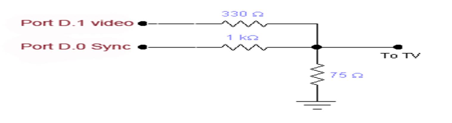
The video
signal was sent out of the D.1 port while the sync was sent from the D.0. The video and sync signal were sent through
the 330Ω and 1KΩ resistors respectively. The 75Ω resistor was set to
ground. As the picture below shows, the
3 resistors were in parallel. The
modified signal is then sent to the NTSC TV.
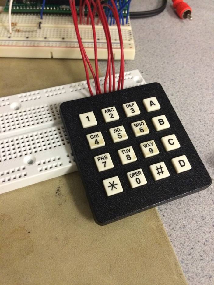
The keypads
are attached to the A ports and the B ports.
The first keypad (the one with the red wires), uses the number 4 for moving left, 5 for moving
down, 6 for moving right, 1 for rotating the piece counter-clockwise, 3 for
rotating the piece clockwise, and 2 for storing the current piece to save it
for later. This keypad is connected to
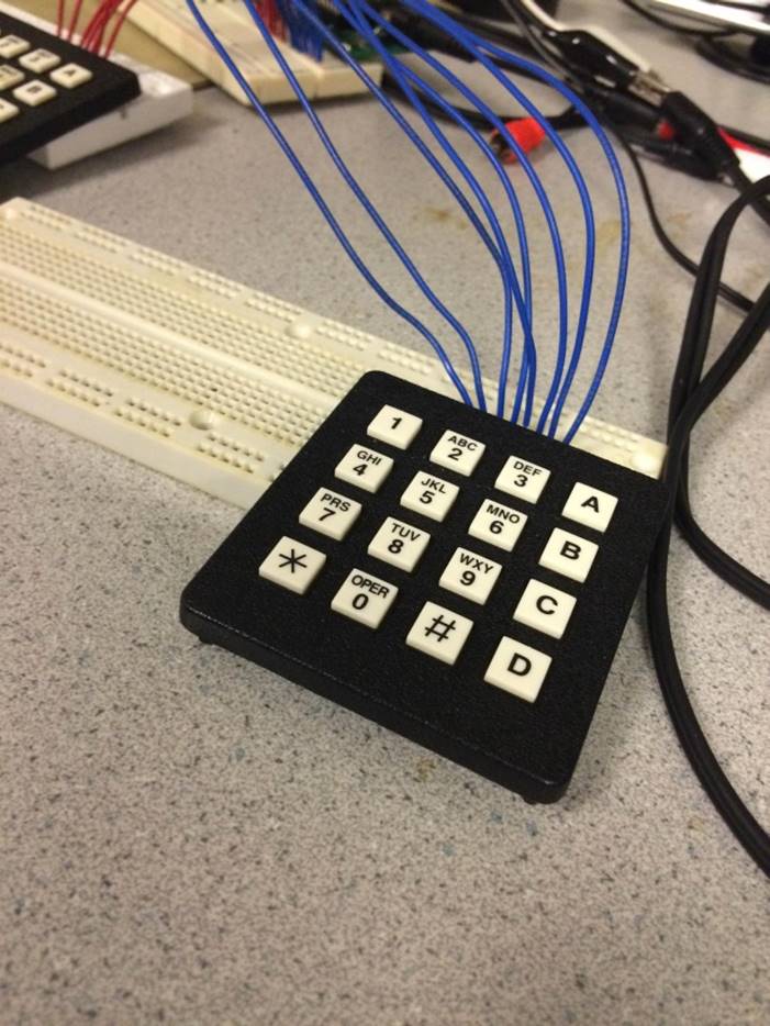
the A ports. The second keypad (the one
with the blue wires), uses the number
5 for moving left, 6 for moving down, B
for moving right, 2 for rotating the piece counter-clockwise, A for rotating
the piece clockwise, and 3 for storing the current piece to save it for
later. This keypad is connected to the A
ports.

Software Design
The software
was implemented in a step by step procedure.
I used the demo code from the video game lab as a basis for my project. It uses two interrupt service routines. The TIMER1_COMPA
ISR updates the Line_Count and continuously sends
data from the ATMega1284p to the NTSC TV. The TIMER1_COMPB ISR puts the CPU to
sleep just before the TIMER1_COMPA ISR goes off.
Coming into
this lab, I knew I wanted to implement the software first using the simple DAC
used in the video game lab. I first
compiled the demo code and made sure I was able to send a complete video signal
to the NTSC TV. Also, I first
implemented a one-player tetris game before
attempting two player.
I then began
to test drawing different pieces. I drew
a simple 4X1 piece by drawing 4 different lines. However, realizing that it may be difficult
for the player to see the board as really a grid, I instead made the piece by
drawing four different small squares.
The draw_square function takes a coordinate and
draws a 6X6 square (10X10 for one player) with the coordinate in the top left
corner of the square. Each piece calls
this function 4 times with different coordinates. For example, the 4X1 piece
would call draw_square for the coordinates (x,y) (x+1,y) (x+2,y) and
(x+3,y).
After I was
able to draw the pieces, I tried to move the pieces down the screen. I first developed a random number generator
that chooses a random number between 1 and 7.
This number will determine what piece to draw. I had a variable called update_piece
that would be incremented every time the TV redraws the screen. Once update_piece
hits 100, I delete the current piece by drawing over it with black and redraw
the piece with the y cooridinate incremented by
one. The pieces move faster as the game
goes on. This process continues until
the current y-coordinate hit the bottom of the playing grid. Once that happens, the random number
generator picks a new number and then draws the specified piece back at the
top.
I then had
to find a way to make sure the pieces would stack on top of each other. This
was one of the hardest parts of the lab.
After a couple misfires, I came up with an idea of creating a matrix
that represents the playing grid. It is
initialized to hold zeros. Each piece
created is contained in a struct called shape. That struct holds a 4X2 matrix that holds the coordinates the
piece takes up with its four squares.
Once the first piece hits the bottom, the matrix is updated. The matrix
coordinates that match up with the pieces struct
matrix are changed from zeros to ones.
Now, whenever a piece moves, it checks if the matrix has a one where it
is about to move. If it does, the piece
must stop and a new piece is created.
After the
pieces were stacking on top of one another, I implemented the keypad. While implementing the right, left, and down
was simple, the rotating was rather difficult. I created a “spin” variable that
would jump through the numbers 0, 1, 2, and 3.
When you click the clockwise or counter-clockwise, the spin variable is
incremented or decremented respectively.
This number determines which way we drew the current shape. I had to add
much more implementation to my shape drawing functions. Each shape (besides the 2X2 shape since it’s
the same no matter how you rotate it) had to add ways of drawing the shape. For
example, if we wanted to rotate the 4X1 piece that has the coordinates
mentioned above, the piece would need to now have the coordinates (x,y) (x,y+1) (x,y+2) and (x,y+3).
After
implementing the keypad and debouncing, I determined
how to delete lines. I check whether or
not a full line of the board matrix is filled with ones after a piece hits the
bottom. If that’s the case, I delete the corresponding lines, move the grid
down the amount of lines deleted, and continue the game. Once I implemented 2 player, I updated the opponents grid as well by creating “non-deletable”
below their grid which pushes their board closer to the top.
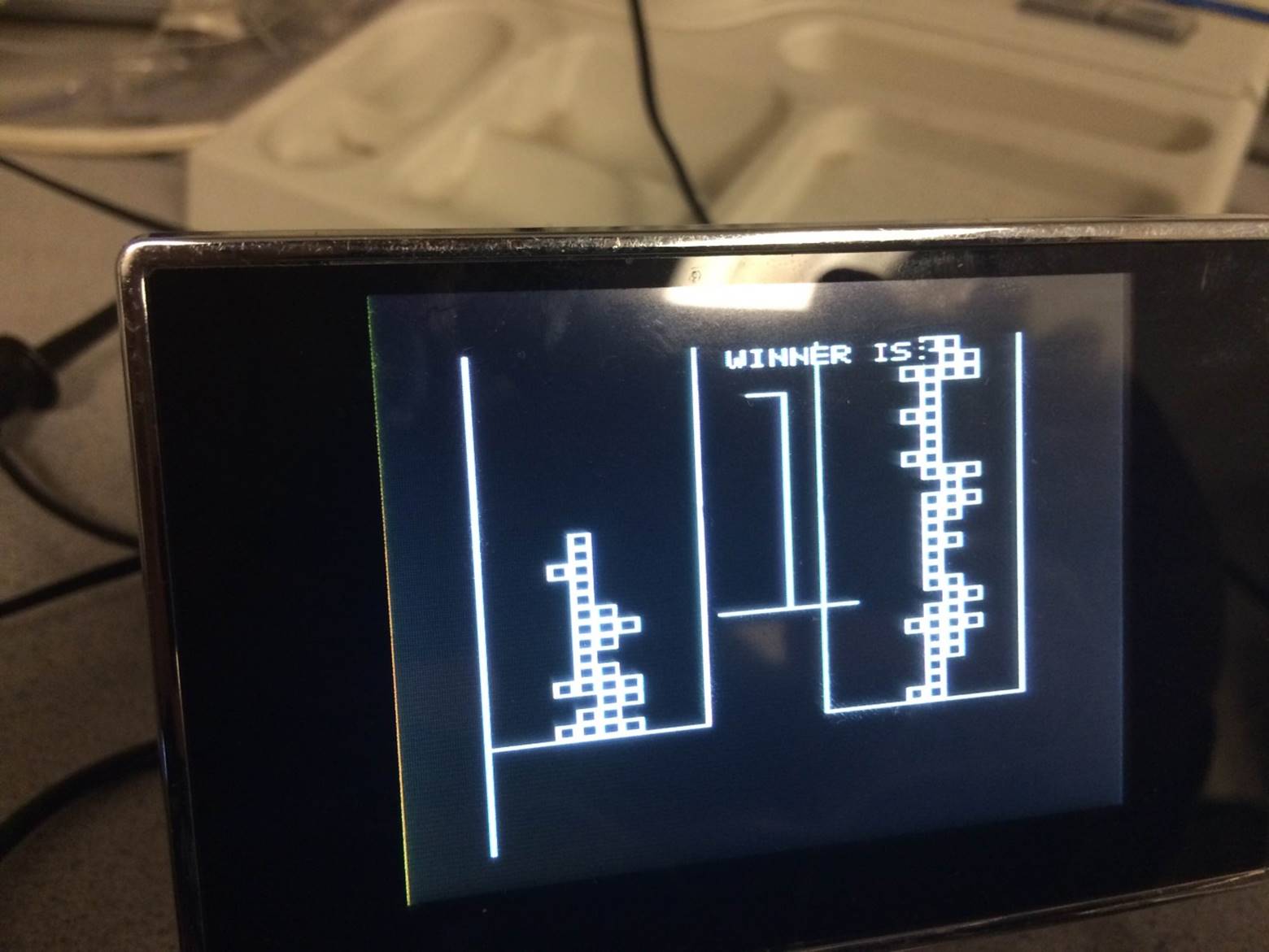
Results
I wasn’t
able to reach the initial goal of grayscale.
Nor did I implement sending a bad piece to the opponent once we clear a
line. But other than that, everything
else works very well. The pieces flow
very well, the picture is very clear with no noticeable noise, and the video
game plays just like a normal tetris game. The debouncing
isn’t perfect. Sometimes the keypad will
think you clicked a button twice when you only meant to click it once. But it isn’t incredibly damaging the overall
gameplay.
The software
took up a lot more time than I expected.
The hardest part of the software was probably coming up with a way to
have the pieces stack on top of each other.
Debouncing was also tedious. I had trouble finding a good frequency of
polling the keypad that would perfectly debounce the
system.
Conclusions
I reached my
goal of making a two player Tetris game that accurately implemented all of the
normal gameplay of a Tetris game as well as some rules that I added. I was unable to add grayscale to my project.
The video
code follows the NTSC standards. Our screen
refresh rate is 60 frames per second and 262 lines per frame. ANSI C
standards were followed when writing code for the project.
I re-used some of Dr. Bruce Land’s
Debouncing code from Lab 2: Cricker
Call Generator and his video signal code from Lab 3: Video Game.
We, the members of the IEEE, in
recognition of the importance of our technologies in affecting the quality of
life throughout the world, and in accepting a personal obligation to our
profession, its members and the communities we serve, do hereby commit
ourselves to the highest ethical and professional conduct and agree:
- to accept responsibility in making decisions consistent
with the safety, health, and welfare of the public, and to disclose
promptly factors that might endanger the public or the environment;
I can see no
safety hazards in my project.
- to avoid real or perceived conflicts of interest
whenever possible, and to disclose them to affected parties when they do
exist;
There are no
perceived conflicts of interest
- to be honest and realistic in stating claims or
estimates based on available data;
his project is honest in stating claims or estimates
- to reject bribery in all its forms;
No bribery
was offered to me during the making of this porject
- to improve the understanding of technology; its
appropriate application, and potential consequences;
I explain
the technology and software of my design in heavy detail.
6.
to maintain and improve our
technical competence and to undertake technological tasks for others only if
qualified by training or experience, or after full disclosure of pertinent
limitations;
This
project gave me more of a grasp on problem solving through programming
- to seek, accept, and offer honest criticism of
technical work, to acknowledge and correct errors, and to credit properly
the contributions of others;
I had a few
of my friends play the game with me and they gave me helpful criticism. Thank you to Dr. Bruce Land for the debouncing and video signal code.
- to treat fairly all persons and to not engage in acts
of discrimination based on race, religion, gender, disability, age,
national origin, sexual orientation, gender identity, or gender
expression;
No
one was treated poorly during this project.
- to avoid injuring others, their property, reputation,
or employment by false or malicious action;
No one was
injured during this project
- to assist colleagues and co-workers in their professional
development and to support them in following this code of ethics.
Appendix A: Cost
Details
· 3 White Breadboards = $7.50
· Mega1284 Microcontroller = $5.00
· 2 Keypads = $12.00
· 12V power supply = $5.00
· 9V power supply = $5.00
· NTSC TV = $5.00
Appendix B: Code
Click link for software:
Tetris.c file:///E:/Tetris_c.htm
Functions.c file:///E:/functions_c.htm
Appendix C: Schematics

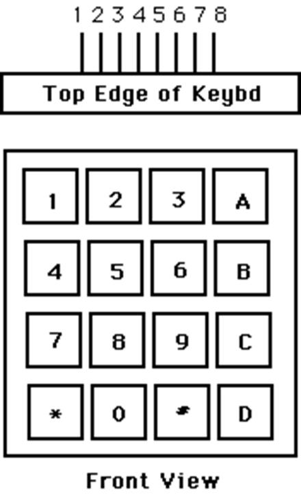
|
Pin 1 |
Row 1 2
3 A |
|
Pin 2 |
Row 4 5
6 B |
|
Pin 3 |
Row 7 8
9 C |
|
Pin 4 |
Row * 0
# D |
|
Pin 5 |
Col 1 4
7 * |
|
Pin 6 |
Col 2 5
8 0 |
|
Pin 7 |
Col 3 6
9 # |
|
Pin 8 |
Col A B
C D |
Appendix D: Code References
Dr. Bruce Land’s Video Generation Webpage and Code
Dr. Bruce Lands Debouncing Code
http://people.ece.cornell.edu/land/courses/ece4760/labs/f2014/lab2code/debounceGCC644.c