Introduction to the Wearable Technology
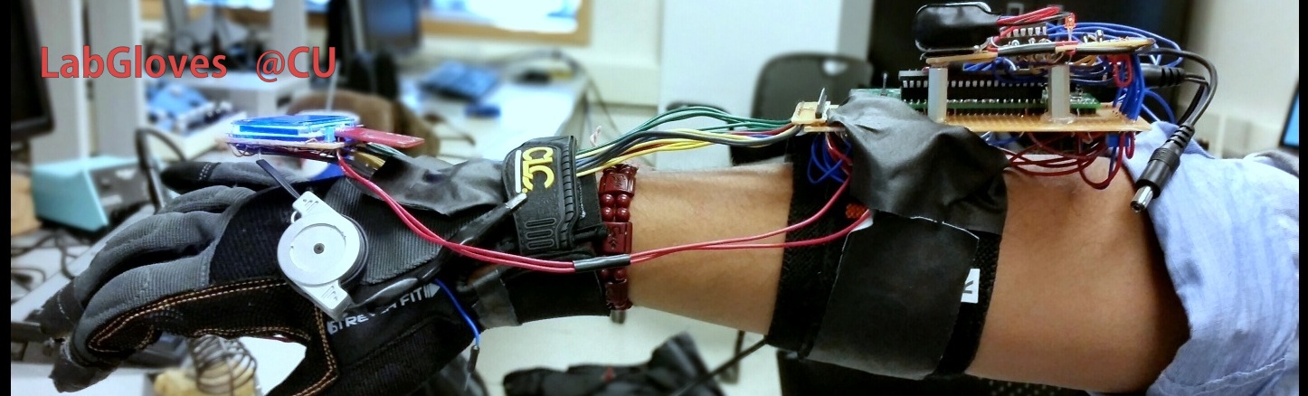
LabGloves brings the functionality of a high end digital multimeter to anyone’s fingertips for an affordable price. LabGloves was conceptualized as a way to simplify an individual's in lab experience by providing the measurements a Digital Multimeter would at the user’s fingertips, but it grew into more. Our group made an effort to take advantage of the Atmel 1284P Microcontroller’s versatility to make an affordable device with functionality found in high end MultiMeters with a slick user interface for intuitive mode control.
All the functionality of LabGloves is made possible through the Atmel 1284P microcontroller and peripheral circuits. Essentially the wearer only needs to select a mode and touch their fingertips to a circuit to gather autoranging readings. This makes it easy to get readings in spaces that a multimeter would be hard to handle, such as behind a wall, in tight spaces, or anytime it proves difficult to hold two hands to a component for analysis.
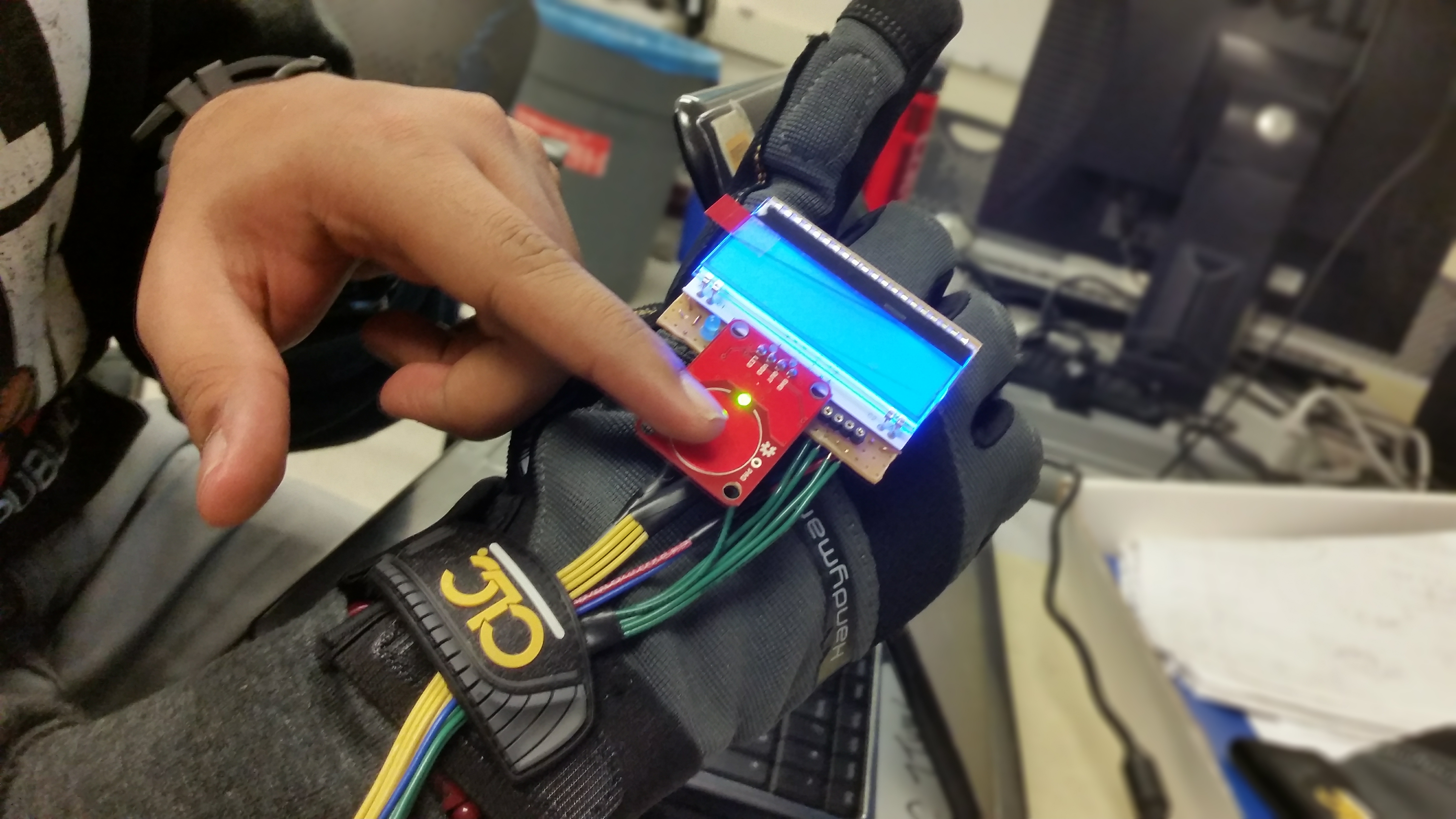
Figure 1. LabGlove User Interface Module
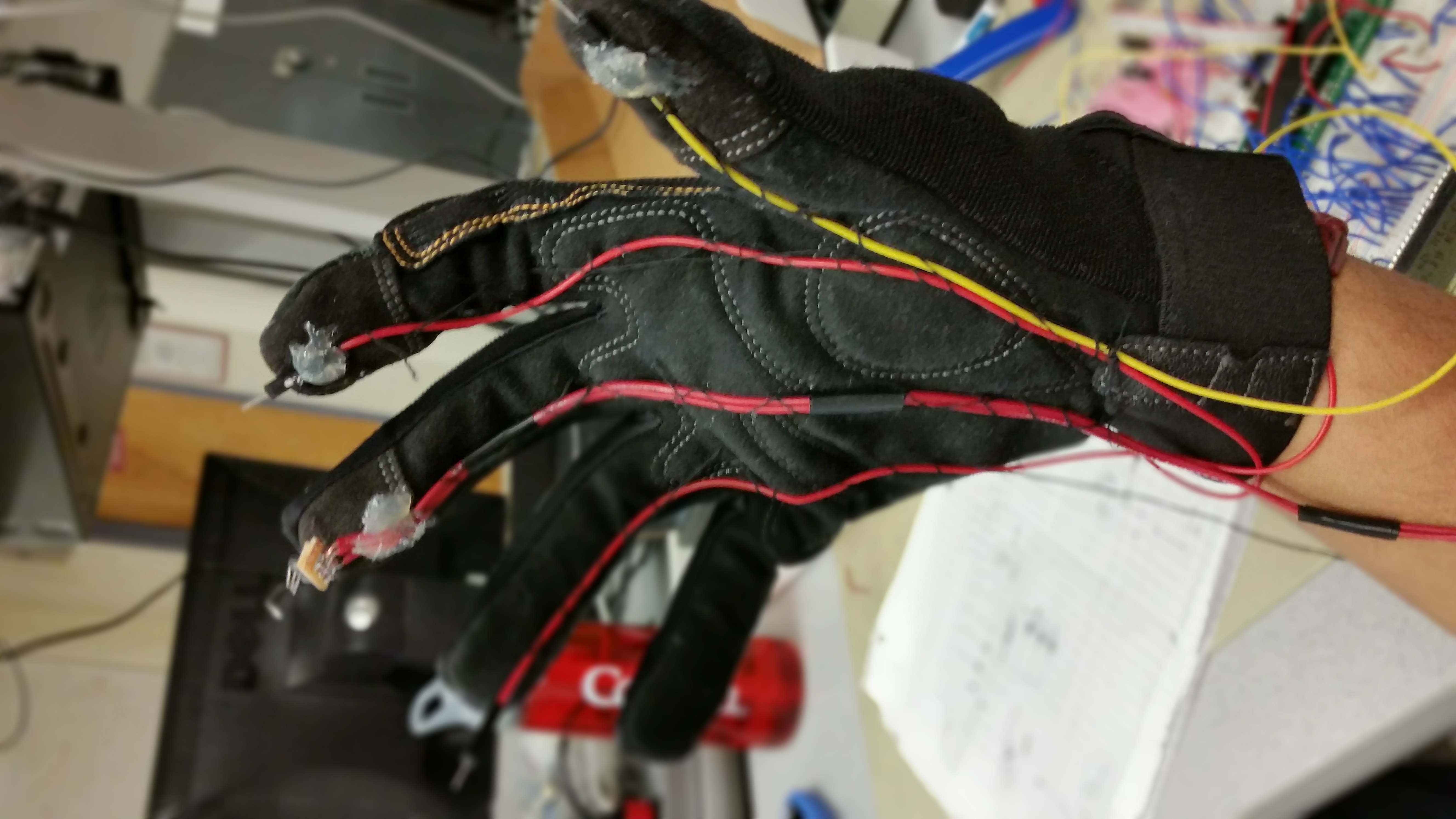
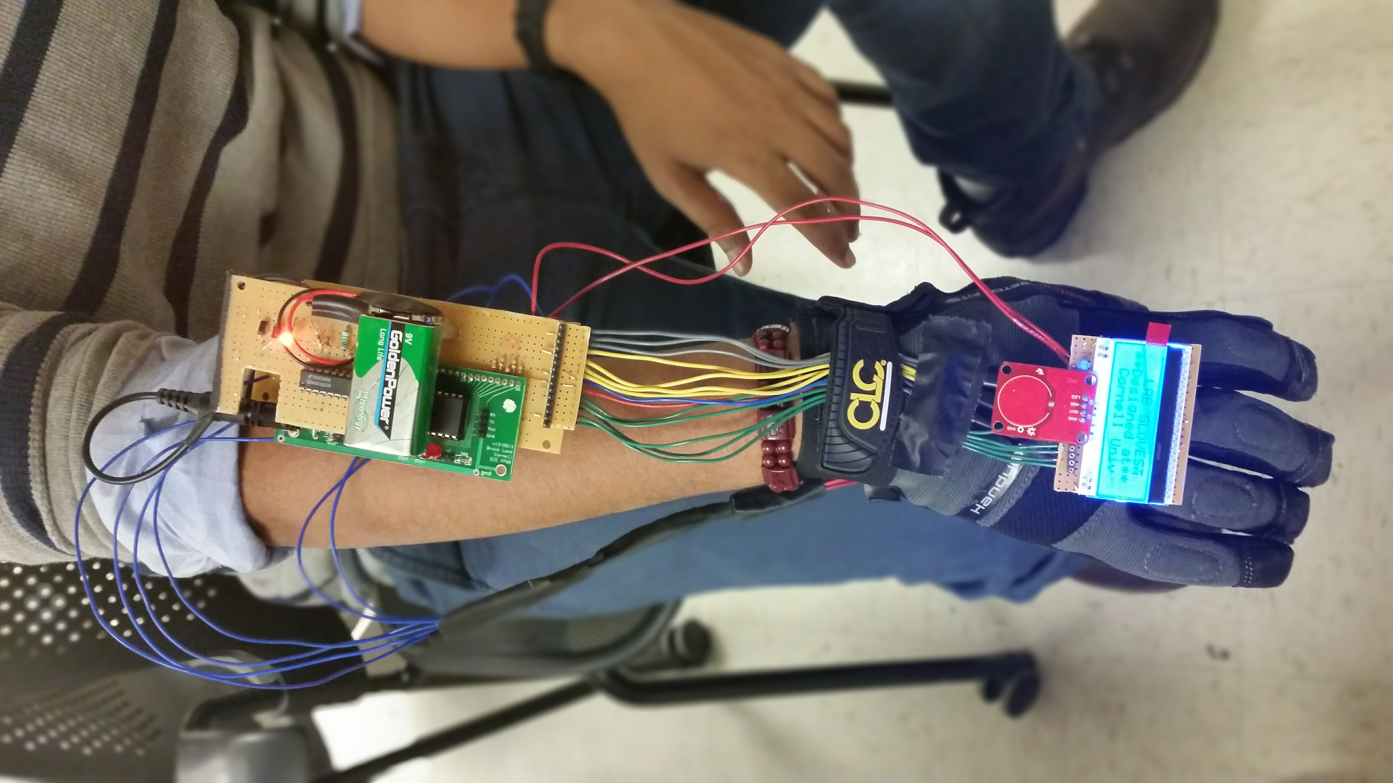
Figure 2,3. Wired Probes on the LabGlove & LabGlove with the forearm module attached
LabGloves Concept top
Hands are one of the most highly utilized parts of the human body and especially the fingers which interact with the external environment the most. This thought kindled our group's thought process to design a wearable device that will take an advantage of using the fingers for making electrical measurements.
In quality control testing and process applications different parameters such as surface thickness, temperature or even point-to-point voltages are required to be measured very frequently. Even in a lab environment it is somtimes cumbersome to use a traditional multimeter to probe the circuit values. With the LabGloves© one can just slide in a glove and measure the parameters on finger tips. Although the current iteration of the LabGloves cannot be referred to as wearable device but prospective development aims at reducing the form factor of the design and making the entire setup to fit on a glove surface.
It is important in the future development to realize the entire design of the LabGloves in a form thatcan fit over the flat surface of the hand. We talk more about this future planned design in the 'Future Work' section.
High Level Design top
LabGloves is comprised of analog signal processing circuits that convert every reading into 5V logic level signals for pins on the Atmega 1284p MCU. The MCU then calculates readings and displays them on our LCD display, which is also mounted on the glove. The user can also change reading modes with a capacitive touch button, as indicated by the user interface displayed on the screen.
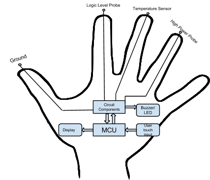
Figure 4. High-Level Design Block Diagram
Rationale and Inspiration:
Our goal while brainstorming this project was to create something that could be useful to many people in every-day applications. We finally arrived on the idea of LabGloves based on the observation that people often find tasks more convenient when everything they need is at their fingertips. This allows people to avoid carrying tools around, and makes it so they can use their own hands to manipulate their work in an intuitive way. With this in mind, we were sitting in ECE 4760 lab (directed by Dr. Bruce Land at Cornell University) using a probe when we finally found our inspiration to design a wearable multimeter.
We found that this was a project unique from work done by previous groups in ECE 4760, and after a search of the US Patents and Trademark Office website it appears this is something that has yet to be attempted elsewhere as well. Particularly, we found that voltmeters, frequency measurements, and similar meters have been developed on microcontrollers—such as the PIC variant, or on the Atmega 644 in previous ECE 4760 labs—but that fully functional, autoranging multimeters seem only to exist as commercially developed products, such as the one pictured in Figure 5 -
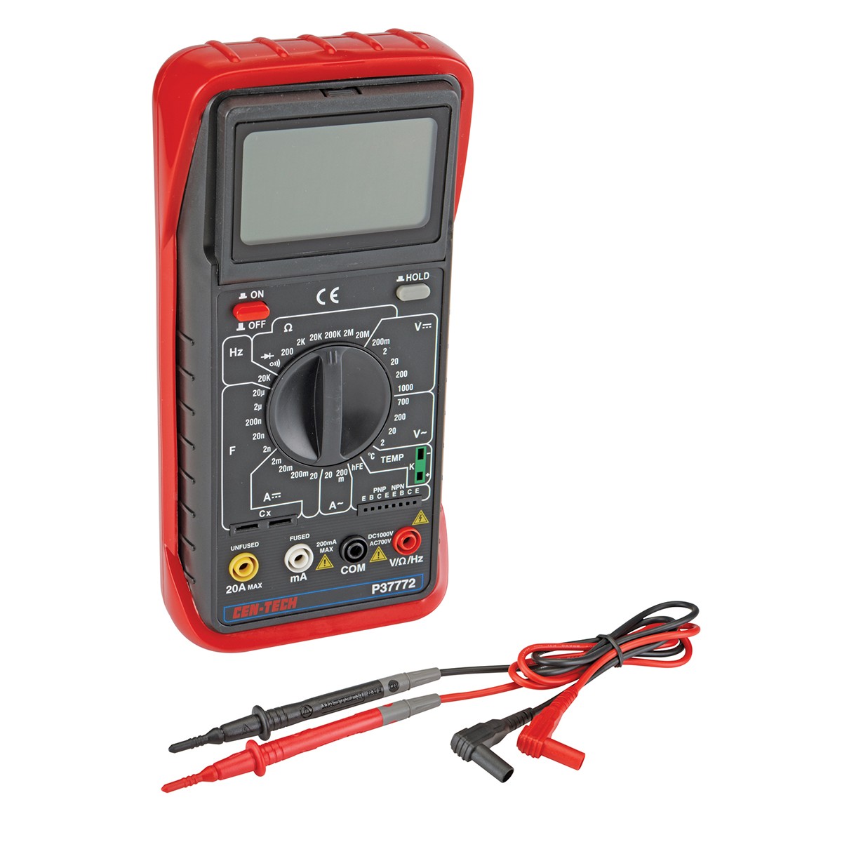
Figure 5. Commercial Multimeter
Naturally, our goal was to design and build an autoranging multimeter with as many measurement modes as possible given a month long timespan for development. The outcome was a wearable device that can perform Voltage, Temperature, Resistance, Capacitance, and Frequency readings (and subsequently Pulse Width and Duty Cycle measurements), and that can perform connectivity, diode, and transistor testing. This is significantly more functionality than past projects and labs from ECE 4760 or found in online searches. Moreover, because we successfully implemented autoranging beyond that done in the past in 4760, we feel that our project is very successful considering our initial goals.
Background Mathematics:
As our digital multimeter (and all digital multimeters) actually only measure voltage, we had to use several algorithms to extrapolate all readings from voltages. Refer to Table I below.
Resistance |
|
Capacitance |
|
Frequency |
|
Pulse Width |
Determined by capturing negative edge of signal from source. |
Duty Cycle |
|
Temperature |
|
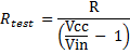
Table 1. Equations Used in the Calculations
Logical Structure:
Lab gloves boots to a splash screen where the user can then select a mode. Once a mode is chosen our MCU changes port configurations to select peripheral circuitry that is appropriate for each mode and makes the applicable calculations for measurements, such as what resistances to select on a MUX for proper ranging.
Hardware Tradeoffs:
We decided to use an analog DEMUX to autorange resistance and capacitance for this project, and our voltage input runs through it, so we will have to use relays of some sort if we want to work in higher powered systems in the future because the CD4051BCN 8:1 analog DEMUX has voltage limits of around 15V and current limits of up to 1 amp. For this reason, we decided to have a separate high voltage sensing mode in which we send voltages higher than 5V through a 1/10 divider to a different ADC pin on the MCU than for LV modes.
Existing Products:
Much like our project, modern digital multimeters actually only measure voltage. Current is measured as the voltage across a shunt and resistance is measured by measuring the voltage across the resistance with a constant current flowing through the resistance.
How a digital voltmeter works internally depends on the manufacturer. The early meters used a dual-slope integrating digital conversion technique that was reasonably accurate and good at suppressing noise. It is slow however, about ten readings per second or less. With modern digital signal processing, over-sampling 1-bit delta-sigma converters can perform with better accuracy, and usually more rapidly.
A side benefit to digital signal processing is the ability to measure time intervals, and hence frequency of an AC signal, or the time to charge a capacitor with a constant current to a specific voltage, and hence measure capacitance. Virtually all digital meters, and some analog meters, feature a "beeper" to allow continuity (low resistance, open or closed circuit) measurements without viewing the meter. Some "multimeters" now even include low-bandwidth waveform display and recording functions, much like an oscilloscope.
LabGloves has the advantage of timers on its MCU so it can measure all of these things, and its placement on the user’s fingertips allows for operation that is unique from any multimeter on the market. With continued improvement in read outs, we are confident that our project has great potential to make an impact to multimeter users everywhere.
Integrated Design top
Capacitance measurement:
The approach we used was similar to that used on the ECE 4760 Labs listing from Fall 2014, which is what we will base this section of the project description on. The idea is to measure the time it takes for a RC circuit to charge a capacitor to a given level. If R3=R4 in the schematic below then the level will be v(t1/2)=Vcc/2. Specifically, we used the internal analog comparator as shown in the following diagram to trigger a timer1 event. In our case, we connected a trimpot in place of R4 to fine tune the capacitance meter for accuracy. Since R2 will be known, we can get C because the voltage on the capacitor, v(t)=Vcc(1-exp(-t/τ)) with τ=(R2)*C. We used an analog DEMUX to select different values for R2 (1k 20k and 100k) to autorange the capacitance readings.
The resistor going to PortB2 should be around 100 ohms to limit current. R2 must be chosen such that the capacitor charging time is not too short or too long, so that must be considered when implementing autoranging. If the charge time is too short you will lose measurement accuracy. It if is too long, the timer will overflow.
.jpg)
Figure 6. Simplified Circuit for Capacitance Measurement (Credit Bruce Land)
Our program executes in the following order:
-
Set PortB3 to an input.
-
Drive PortB2 to zero by making it an output and wait long enough to discharge the capacitor through 100 ohms. Clearly, to discharge to zero volts with 1% accuracy, R2>100*(100ohms).
-
Convert PortB2 to an input and start a timer. The capacitor will start to charge toward Vcc.
-
Detect when the voltage at PortB2 is greater than the voltage at PortB3. That is, you will have to record when the comparator changes state using the timer1 input capture function, which is set up to be triggered by the comparator. Using input capture gives better timing accuracy and more dynamic range.
-
Switch to a smaller resistance on the analog DEMUX if your timer overflows, or if you read an unusually small charge time (such that your resolution is not enough for good accuracy) switch to a larger resistance.
-
Repeat
If you are using an AVR Microcontroller, something the 4760 lab page mentions is that if you decide to print floating point numbers to the LCD you need to follow the directions in Using sprintf function for float numbers in AVR-GCC the AVRstudio directions are at the bottom of the page, but NOTE that one library is left out. The correct summary is:
Open the Project>Project Configuration dialog box, then go to the custom options , then select linker options, and then add the
-Wl,-u,vfprintf -lprintf_flt -lm and -Wl,-u,vfscanf -lscanf_flt -lm switches.
Low Voltage (<= 5V), High Voltage (5V< v < 20V), Resistance, and Frequency:
Again, for voltage, resistance and frequency measurements we referenced work done in a 4760 lab from Fall 2012, which can be found on the course page. Something to first note are that the 1k resistor and diodes protect the analog input (A0) from over/under voltage. See Figure 3 below.
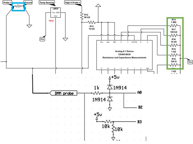
Figure 7. Circuit for Resistance, Voltage, and Frequency Measurements
Low Voltage measurements were taken by setting up the internal ADC to take measurements from A.0 on the MCU. We set Vref to Vcc, and found that there were good accuracy measurements above 100mV. However, one could autorange voltage better by changing Vref internally for smaller, more accurate measurements. High voltage measurements were taken using a voltage divider that divides any input voltage by 10.
We have 5 decade resistors (Green Box in Figure3) from 100 Ohms to 1 Mega Ohm (shown in Figure3) connected to an analog DEMUX. We turn them on (one at a time) to autorange and measure resistance. The tristate i/o pins make it very easy to connect a resistor to ground (output-low), Vcc (output-high), or disconnect (input-no pullup). We are measuring the voltage that results from division with a known resistance value coming from the DEMUX, so if we denote one of the five resistors as R, and the resistor-under-test connected to the probe as Rt (Blue Box in Figure3), then Rt = R/(Vcc/Vin - 1). The sensitivity of the resistance measurement decreases as Vin increases, suggesting that we should keep Rt<<R. However, low Vin means significant quantization error in the ADC. We keep Vin between about 0.1*Vref and 0.9*Vref during resistance measurements for 5% accuracy. We autorange resistance by turning different resistors on to divide voltage closer to logic level for MCU operations.
B2 is the input to the internal comparator, which we also use for capacitance measurements, but we use it here for frequency measurements. B3 is the reference pin for the comparator, which is divided to Vcc/2. Similar to making capacitance measurements, we set up the timer1 interrupt to trigger at the positive clock edge, and set a timer that counts on a 0.5us timescale as the prescalar for timer1 is set to divide the crystal frequency by 8 in our code. We autorange frequency by changing the timer 1 prescalar.
Additionally, we also detect the pulse width of an input signal by interrupting on each positive and negative edge on the comparator connected to timer1 and keeping track of the timing for both positive and negative edges. We are therefore able to calculate the duty cycle of an incoming wave using ![]() , where T is the period of the incoming signal.
, where T is the period of the incoming signal.
The probe input goes to the ADC and internal comparator. This example from the ECE 4760 course page (ADCtestGCC644.c, uart.c, uart.h, project zip) shows how to set up the A/D converter to read a trimpot.
This example (also from the course page) shows how to get higher ADC accuracy by putting the MCU to sleep during the conversion to cut down digital noise. Note that some special timing code has to be added to make the UART work correctly when you put the MCU to sleep.
Something Important the 4760 lab we referenced mentioned is that you may want to check the V-reference impedance and the capacitance (if any) placed from Aref to ground on your board. On the Mega644 board it is 30 kohm with a 20 nF capacitor placed from Aref to ground. This implies the time-constant to CHANGE Vref is 3e4 x 20e-9 = 60e-5 or 600 microseconds! This means that to get 8-bit accuracy after you change Vref, you must wait 1/256 = exp(-t/600) or t~3 mSec before doing another conversion! The calculation is similar for any board after inspecting the datasheet.
Transistor Testing:
The test sequence for a transistor works like this in our code:
- Set D2 High and read D1 and D3. If D1 is High, BE junction conducts, otherwise not. If D3 is High, BC junction conducts, otherwise not.
- Set D1 High and read D2. If D2 is High, EB junction conducts, otherwise not.
- Set D3 High and read D2. If D2 is High, CB junction conducts, otherwise not.
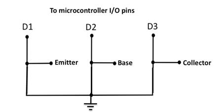
Figure 8. Transistor Testing Circuit
Now, if only the BE and BC junctions conduct, the transistor is of NPN type and is working fine. And, if only the EB and CB junctions conduct, the transistor is still normal but the transistor type is PNP. All other cases indicate the transistor is no good (such as EB and BE both conduct, or BC and CB are both not conducting, etc.).
Diode Testing:
This is also taken care of at the low voltage probes. This essentially checks to see if the diode approximately drops 0.7V (as per standard designs) through ADC0 on our MCU. If 5V is passing to the ADC, we know the diode has broken down and basically become a short, otherwise, if there is no voltage on the ADC, we know that either nothing is connected or the diode is connected in reverse bias, which we display on our LCD.
Temperature Testing:
For Temperature Sensing we used the LM35 Precision Centigrade Temperature Sensor. A quick look at its datasheet reveals that the LM35 has a range of 2 ֩C to 150 ֩C when no load on the output. The voltage change with respect to temperature is basically linear, so we simply multiplied the incoming voltage detected by ADC7 with a scalar.
Connectivity Testing:
Connectivity testing was done by connecting an LED from pin D.0 to the cathode probe. When in this mode we set D.0 high, so when something is connected across the probes, current flows from D.0 through the LED and to ground, illuminating the LED.
Everything was carefully soldered onto a two level, through hole PCB configuration, which we then mounted on an arm strap which holds the MCU. Connections are then soldered from there to the LCD display, touch button, and testing circuits on the gloves.
LCD Display:
The LCD display used in the setup is a 16x4 dot matrix display – EA DOG-M 163W-A series LCD. More information about the display can be found here in the datasheet. We had to write our own library functions for interfacing with the code. The header and C files for the LCD are attached at the end in the appendices section.
The backlight for this LCD comes as a separate module- we got the EA LED55x31-B backlight module from DigiKey and interfaced it with the LCD module package by soldering the back light LED pins. The LCD was interfaced using +5V 4 Bit interface connected on the PORT pins C0-C3 and control pins on the C5-C7.
Detailed connections of the LCD can be found here in the overall schematic.
Programmer:
We used an AVRISP MK II programmer provided by Prof. Bruce R Land. The ISP programming frequency was set to 4 MHz for higher writing speeds. Fuse bits and JTAG connections were checked as per ECE 4760 Lab 1 instructions. We did experience some glitches while programming the MCU when it would automatically reset itself while programming. Resetting the system helped us to overcome this problem.
.jpg)
Figure 9.Test Circuit Used for Debugging
The Overall Multimeter Schematic can be found here!
Software Development top
The software structure used in building the LabGloves© is built using the following steps –
Variable/Function Declarations - We included all the required header files and associated C files including the ones for the LCD. This section also includes all the function declarations, variable declarations, LCD display buffers. We have defined each of the LabGloves© mode as a system state, by checking the system state variable the DMM function understands which case to switch ( ) on.
Interrupt Service Routines -
ISR (TIMER0_COMPA_vect) compare vector interrupt is used for scheduling the tasks. The main function ensures that the functions are timed based on the value of ‘T’ loaded into the ‘time’ and when it goes down to 0 the ISR triggers executing the functions in the main ( ).
ISR (TIMER1_CAPT_vect) – The ISR capture vector interrupt is to capture the value of ICR variable for making the frequency and capacitance measurements. It is linked internally with the analog comparator which executes the ISR when the comparator triggers. This ISR also consists of a logic that switches the ‘positive edge detect trigger’ to the ‘negative edge detect’ for calculating the Pulse Width and Duty Cycle without affecting the ‘time_capture’ variable used in capacitance measurements.
Key Detect Function & Debounce State Machine – The capacitive touch breakout board is interfaced on the PIND.0 of the MCU. The output pin of the board goes HIGH when pressed and is otherwise LOW. Thus, by detecting the state of the PIND.0 we detect the switch press and pass it through the debounce state machine for avoiding the bouncing of the switch. We are using a time constant of 50 ms to check the debounce, since the average fastest human response is > 100 ms.
Set and Reset PIN Logic – In different modes of the DMM we are setting the PINS of the MCU to a logic level not required by other modes. Thus, it is required to set the PORT PINS based on the system_state and reset it back once the mode is changed. This logic takes care that the PINS are restored back in the state they were by default so that the other modes are not affected. This gives us the flexibility of setting the port PINS the way we want in any given mode without bothering about the other modes.
Main ( ) Function – This is where the program enters at the beginning. It runs the initialize ( ) at the beginning to initialize the LCD, timers, PORT PINS and DDR for all the PORTS. After that the main ( ) simply acts as a scheduler to schedule the tasks at a given rate fixed initially. The main ( ) executes in a while (1) loop and runs continuously until the system is shut down by the user.
DMM Compute Function – This is the heart of the overall software development. Based on the existing system_state these functions switches on different modes. It executes the logic written down in each of the code and generates the value - displays it on the LCD. It gets scheduled by the main () continuously after a certain time period. Each of the DMM case corresponds to a mode on the LabGLoves© and ensures that the display is wrapped after next three successive modes.
Initialization Function – As described earlier the initialize ( ) takes care to set all the PINS and TIMERS along with setting up the ADC and initializing the LCD display, setting up the global interrupts. It sets up different flags and system_state in a way that they are used throughout the execution of the program. This function gets called at the beginning of the main ( ).
Specifications top
- Specifications - (Includes Technical and Product Specifications) We need to include the actual expected specs and how much did we get them in the performance. Make a comparative and statistical study of it.
A. Technical Specifications -
Specification |
Speed |
Accuracy |
Safety Considerations |
||||||||||||||||
Low Voltage (<5V) |
This is limited by the rate at which we are able to change Vref: the time-constant to CHANGE Vref is |
|
We implemented a High Voltage alert for when the voltage approaches 5V, and we were sure to keep the low voltage probe separate from the high voltage probe. |
||||||||||||||||
High Voltage (5V+) |
This is also limited by the ADC. |
|
We used a voltage divider on this line to ensure the MCU never received anything close to 5V. |
||||||||||||||||
Frequency |
You get to the limits of the timer at 45KHz+, and you have overflow below 30Hz. |
|
|
||||||||||||||||
Resistance |
Again, this is mainly limited by the speed of the ADC input, and also by the time it takes to find the proper resistance for autoranging (this is usually done on a couple of iterations after the ADC is complete, on the order of us). |
|
|
||||||||||||||||
Capacitance |
Like Frequency, this is limited by the 16 bit timer in the Timer1 Capture Register. This can be helped by simulating a 32 bit timer with an overflow count, and it can be helped by autoranging. |
|
|
Table 2. Technical Specifications for the LabGloves
B. Usability
Clearly our design is quite accurate for the most part, and is easy to use with the intuitive user interface. This design makes one handed-operation possible unlike conventional multimeters, and therefore may be useful to people who only have the use of one hand. This also allows great dexterity and control as opposed to conventional probes, which may be useful to those suffering from arthritis. In general, LabGloves© could potentially make working in the lab easier—to the extent people may forget they are even wearing them—until they need a voltage measurement of course!
-
Capacitance – 200 pF to 150 uF
-
Resistance – 25 Ohms to 10 MΩ
-
Frequency – 30 Hz to 45 KHz
-
Voltage – 0.1 V to 20 V (tested) / 50 V (ideal)
-
Temperature - 0.2 C to 120 C
-
Transistor – PNP and NPN transistor
-
Diode – VF of 0.7 – 0.9 V
Conclusions top
We set our goals high for this project, aiming to have an accurate autoranging multimeter capable of many of the functions of commercial devices all at your fingertips, and we feel we certainly attained our goals considering our generally low error in measurements, the fact that we provide 11 unique and intuitive measurement modes, and because the final design was certainly wearable—and looks pretty cool once you strap it on!
We reused code from our previous labs in 4760, including the capacitance measurement lab and the tutorials from the 4760 Digital Multimeter lab held in Fall 2012; we also got a kickstart on the libraries for our LCD display from a tutorial on the Electronics Assembly website (the device’s manufacturer). However, all other code implemented in this design was written for the first time by our group specifically for this project.
Standards
Furthermore, our design adheres to the IEE Code of Ethics Chapter on Dielectrics and Electrical Insulation, as we wanted to maximize safety for the wearer of LabGloves.
Intellectual Property Considerations
Our Software was written entirely by our group with the exception of a portion of the code used for our LCD libraries written by Electronic Assembly, Inc, and the bones of our programs relating to Resistance, Capacitance, and Voltage measurements, which were laid out by Bruce Land for Cornell ECE 4760.
Furthermore, our physical design, to our best knowledge, is entirely unique and has not been produced before or protected by patent, trademark or copyright. We have given proper acknowledgement to all third parties who helped us to develop our design project.
A comprehensive list of ethics that we followed while designing our device can be found on the IEEE website.
Legal Considerations
To our knowledge, our device does not violate any legal regulations. However, as a disclaimer, users should be advised that our device is not foolproof, and the user must familiarize themselves with its limits, as indicated in the user interface, and the ranges laid out above in the specifications section.
Future Work top
- Miniaturize using a custom PCB – We would like to design and fabricate a custom printed circuit board (PCB) which can literally fit the size of an average human hand. This will consist of a combination of the circuit components, a Lithium Polymer battery and a flexible LCD display. We even might consider making use of flexible printed circuits so that it gives the user freedom of flexing the hands without worrying about the rigidity of the setup. This will make the device “wearable” in its true sense. We plan to use surface mounted device (SMD) components for all the existing counterparts on the circuit.
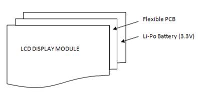
Figure 10. Future Setup Implementation of LabGloves
- Implement AC/DC current and AC voltage in the design – We would like to have an additional functionality of measuring the AC-DC current and AC voltage using the LabGloves. This will make it complete in terms of DMM functions. The real challenge lies in shorting a wire while measuring the current in a circuit and making it pass through the internal components.
- Make a single board for all including the MCU – We plan to use a smaller 32 pin SMD version of the AVR AtMega 1284P MCU to make the system compact. Instead of using a different prototyping board for the MCU, it will be a part of the main circuit with peripheral components around it. The user interface module will be connected to the main breakout board through the glove fabric. We need to take care of the ergonomic factors and usability while finalizing the design.
- Include the future patenting strategy and market available for its use – We are definitely looking forward to the LabGloves as a future product and it is important for us to protect the intellectual property rights (IPR) associated with it. Right at the beginning of spring’15 semester we plan to file a provisional patent on it to get the protection rights of a year before filing the actual patent. LabGloves©- name of the product needs to be a copyright as well. We plan to approach Cornell University patent and TM office to get directions in this aspect.
- Insulate the Glove for future – It is essential that we provide a right insulation for the glove to minimize the risks it possess to the user. We plan to sandwich the circuit layer between the two insulating layers for full-proof insulation. However, the overall thickness o0f the sandwich is the most important parameter as it should not make wearing the glove an uncomfortable affair.
- Bypassing a mode for other modes – Currently, in the existing setup when the user measures a particular parameter and switches to a different mode it does not take care of the fluctuations in the reading. For e.g.: If you have frequency generator connected to the probes and try to measure capacitance without disconnecting the probes, it will fluctuate the value of capacitance being measured. We need to implement bypassing of other modes when measuring in a particular mode. A combination of SMD MUX’s can do this trick (needs to be researched more)
- Add-On functionalities – It will be very useful if we can get other functionalities such as humidity, surface thickness, level testing etc. on the finger tips. It will be a challenge to implement these functions using a single finger probe.
Understanding the nature of the future work and citing a potential in the LabGloves© our team is planning to take it ahead in the spring’15 semester as an independent study project with Prof. Bruce R Land!
.gif)
Figure 11.Team – LabGloves© !
Appendices top
A. Schematic
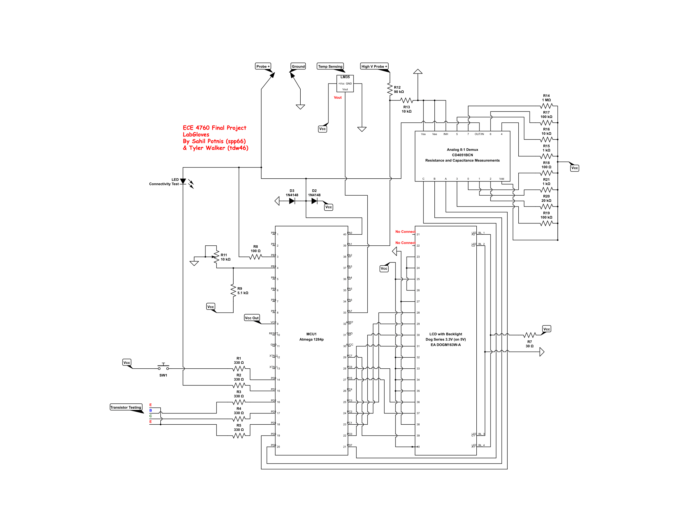
Figure 12. Overall Multimeter Schematic
B. Cost Details
Part Number |
Vendor |
Quantity |
Price |
Total Cost |
ATMega1284P |
Lab stock |
1 |
$5 |
$5.00 |
Pair of Flexible Gloves |
Amazon |
1 |
$13.44 |
$13.44 |
Capacitive Touchpad Breakout Board |
Sparkfun |
1 |
$7.95 |
$7.95 |
EA DOGM 163W-A LCD Display Module |
Lab stock |
1 |
$8 |
$8.00 |
EA LED55X31-B LCD Backlight Module |
Digi-Key |
1 |
$12.08 |
$12.08 |
CD4051BCN 8:1 Analog Multiplexer |
Lab stock |
1 |
$1 |
$1.00 |
LM 35 Temperature IC |
Intel Cup Lab |
1 |
$0 |
$0.00 |
Prototyping Boards (Large & Small) |
Lab stock |
2 |
$4 + $1 |
$5.00 |
Aluminium Spacers |
Lab stock |
2 |
$0 |
$0.00 |
Diodes |
Lab stock |
2 |
$0 |
$0.00 |
Resistors |
Lab stock |
21 |
$0 |
$0.00 |
9V Battery Holder |
Lab stock |
1 |
$0 |
$0.00 |
9V Battery |
Amazon |
1 |
$2 |
$2.00 |
Wires |
Lab stock |
4.5’ |
$0 |
$0.00 |
Velcro Strap |
Borrowed from Travis |
1 |
$0 |
$0.00 |
LED's |
Lab stock |
2 |
$0 |
$0.00 |
DIP IC Holder |
Lab stock |
1 |
$0.5 |
$0.5 |
Total cost |
|
|
|
$54.97 |
C. Distribution of Work
We made use of a Gantt Chart Template to plan and distribute our porject duties. The inital version of our Gantt Chart can be found online here
| Sahil Potnis | Tyler Walker | Combined Effort |
|---|---|---|
| Building LCD Library for ST7036 | Resistance Mode | Proto Board Soldering |
| Capacitive Touchpad Interfacing | Frequency Mode | Report Contents |
| Capacitance, Diode and Transistor Testing Modes | High Voltage Measurement Mode | Stitching Probes on the Glove |
| Low Voltage and Temperature Mode | Connectivity Testing | Buidling the Test Bench for Demo |
| Building the Website | Hardware Schematic | Interfacing the LCD module |
D. Code Listing
Code can be made available on request
lcd_lib_STC.c - LCD Library C file
lcd_lib_STC.h - LCD Library Header File
References top
This section provides links to external reference documents, code, and websites used throughout the project -
Datasheets
- Atmega1284P Datasheet
- DOG Series LCD Module Datasheet
- Sitronix Dot Matrix LCD Controller/Driver
- CD 4051BCN 8:1 Analog Mux Datasheet
- TI LM 35 Precision C Temperature Sensor
References
Vendors
Background Info
Patent Search Info
- We did an extensive patent search on the existing "Glove" based wearable technology using USPTO website and here are the results we obtained
Acknowledgements top
We would sincerely like to acknowledge Prof. Bruce R Land for his overall project guidance and timely smart suggestions which helped us to complete the final project in the provided time frame with required finesse.
We would also like to thank all the TA's for debugging all sorts of errors throughout the semester!