Chiptune Mega Mega:
An nes-style music player with affective computing
Yunji Fengshi (yf88) & Scott Zhao (sz296)
Introduction
Our final project is a NES-style chiptune player that changes its playback tempo in response to heart rate measurements from the user. The chiptune player successfully generates four individual channels: pulse, triangle, noise, and delta modulation. After audio mixing through a hardware circuit, the resulting mono signal sounds as intended, with no waveform clipping present and the PWM carrier frequency blocked. Songs are played by the chiptune player with all four tracks in sync. In affective mode, playback tempo is adjusted to match bpm measured from the user.
High Level Design
Rationale and Inspiration
Despite hardware constraints such as a limited number of sound channels and limited processing power, chiptune composers managed to write expressive, memorable music that has influenced today’s electronic music, inspired an entire subgenre of its own, and continues to provide nostalgia to the generation that grew up with the game console.
A possible application for this is for use during exercise, so that a song is matched to an athlete’s heart rate. Moreover, this affective computing aspect of the chiptune player allows a user experience that is rewarding in its interactivity and customizability.
Logical Structure
One ATmega1284p is used for music generation based on the structure and methods used by the audio processing unit of the Nintendo Entertainment System (an 8-bit video game console). Unofficial (community-produced) online documents and specifications regarding the NES, its audio processing unit, and its sound channels were used extensively. Wherever possible, the chiptune player was designed to match the NES’s APU as closely as possible in structure, but especially in terms of sound generation.
The chiptune player features four unique sound channels: a variable-duty-cycle pulse wave channel, used for melody; a triangle wave channel, used for bass lines; a random waveform channel, for percussion; and a delta modulation channel, for playing low quality, 1-bit delta-encoded samples. Songs for playback are hardcoded using an original scheme to encode note pitch, note duration, and special effects. This scheme features a musically-minded design that allows a musician to encode any song for playback with relative ease.
Concurrently, a second ATmega1284p is used for monitoring heart rate. Measurements are taken from the user and fed as input to the chiptune player, through an 8-bit serial data bus. Playback tempo changes in response to this measured bpm.
The user interface consists of a menu for selecting tracks, implemented through a LCD and push buttons; toggle-switches for muting/enabling individual sound channels; and a heart rate monitor, implemented through circuits described in the Documentation section below.
Background Math
PWM sampling frequency
First, we go over some key calculations of sampling rate used throughout the remainder of this discussion:
Timer0 and Timer1 are set up to generate fast PWM samples, toggling their outputs in non-inverting mode. Since both timers are set to run at full-speed and clear timers at 256, the PWM sampling rate for both are given by:
Timer0’s overflow ISR is responsible for updating the output values of all four sound channels. Note the distinction between updating the output values and generating PWM outputs. ie. Both Timer0 and Timer1 generate PWM samples at a rate of 62500 Hz as explained above, but no ISR is written for Timer1.
However, since all four sound channel outputs are updated within the ISR, computation must be split into two: the channel outputs are updated every other overflow, with updates alternating between the pulse channel and the other three channels combined (triangle, noise, and delta modulation). It was divided in this way because the pulse channel features the most number of special commands, and requires more computation time. As a result, accumulator increment must be adjusted by a factor of two, as explained below.
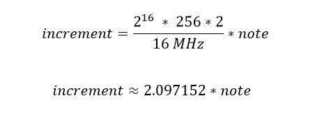
Converting note frequency into an accumulator increment
16-bit accumulators are used to generate the requested frequencies for the pulse and triangle wave channels. The increment with which the accumulator is increased during every other overflow is a function of Timer0’s clock speed and the requested note frequency. The value of increment is given by:
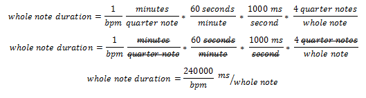
Determining beat duration from bpm
Tempo in beats per minute is converted to a whole note’s duration in milliseconds such that it can be used by the music parser to calculate fractional note durations, which is then counted out by virtual timers within Timer0’s overflow ISR. Given a value for tempo in beats per minute, beat duration in milliseconds is given by:
Delta modulation
Delta modulation is a method for sampling audio signals where quality is not of primary importance. In this scheme, the difference between successive samples are encoded into a 1-bit data stream. The delta modulation channel plays these 1-bit delta-encoded samples. Examples of usage in NES games include semi-intelligible voicework, timpani in Super Mario Bros. 3, and bass lines in SunSoft games.
Hardware and Software Tradeoffs
We chose to implement hardware that would decrease the signal processing that needed to be done by our software, using bandpass filters to isolate the signal and eliminate noise for the biosensors. For the heart rate monitor, we chose to use the microcontroller’s adc rather than building a schmitt trigger as an ADC. This is because the blood flow in each person’s finger is different, the schmitt trigger’s threshold voltage is not practical to adjust for each individual who uses it. Instead, a software implementation that adjusts the threshold voltage to determine a pulse based on the previous reading gives a more flexible result.
The audio mixer is implemented in hardware rather than software. This enables more individualized control of each channel, and increases the modularity of the chiptune player system. As well, this saves computation time in the chiptune player’s Timer0 overflow ISR, which is so computationally intensive that it had to be split into two, as explained in the Background section above.
Existing patents, copyrights, and trademarks
The Nintendo and Nintendo Entertainment System trademark are owned by Nintendo. Our emulation of the NES sound chip is inspired by the NES, but is our own design and does not infringe upon Nintendo’s copyrights. In designing a sound similar to the NES, community-produced documentation and specifications available on the web were used.
The chiptune player contains original covers “Bruises” by Chairlift, “Wishing We Last Forever” as performed by Faye Wong, and “If I Ever Feel Better” by Phoenix. The original compositions are properties of their respective artists and are used solely for demonstration purposes and not personal gain.
Chiptune Player Subsystem
The chiptune player is composed of nine main modules: (1) a 1-millisecond utility timer, (2) variable-duty-cycle pulse wave channel, (3) 4-bit triangle wave channel, (4) pseudo-random waveform channel, (5) delta modulation channel, (6) music encoding scheme, (7) track parser, (8) hardware audio mixer, and (9) user interface.
Chiptune player flow chart
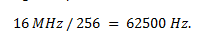
Length timer
Timer0’s overflow ISR generates a one-millisecond time base used to count out note durations. Timer0 is set up to run at full-speed. Triggering at a rate of 16 MHz / 256, 62 overflows closely approximates 1-millisecond. When base_time has reached 62 overflows, base_time is reset, and all virtual timers are updated. There are seven virtual timers: one for each sound channel and one for each push button (for debouncing). If any sound channel’s virtual length timer has counted down to zero, then a ready flag is raised to indicate that the next note can be played. Timer0’s overflow ISR is also responsible for generating PWM samples all four sound channels, each of which is discussed in detail below.
Pulse wave channel
The pulse channel’s output corresponds to Timer0’s PWM output on OC0A. The pulse channel is implemented using the following direct digital synthesis scheme: During every other overflow, if the pulse channel is not silenced, a 16-bit p1_accumulator is incremented by an amount determined by the requested note frequency. p1_sequencer is obtained by right-shifting the result, and is used as an index into a pulse waveform sequence of length 8. The result is scaled to a number between 0 and 255 and then written to OCR0A, updating the PWM output corresponding to the pulse channel.
The pulse wave channel features variable duty cycle: depending on the value of duty requested, the pulse waveform corresponds to either a 12.5%, 25%, 50%, or 75% duty cycle. (Note that a 75% duty cycle is simply 25% duty cycle inverted. Since the human ear is phase-insensitive, these two settings effectively sound identical.) As an example of usage, one popular technique used by chiptune composers is to attack (begin) a note at 50% duty cycle, and quickly back off mid-note to 25% duty, creating a pluck-like sound effective for simulating string instruments.
This channel also features a frequency sweep function. Upon request, the pulse wave channel performs a continuous frequency sweep between two notes. p1_incremented is updated at a rate of 120 Hz in the following manner: First, p1_increment is right-shifted by 7. The result is either added to or subtracted from the current value of p1_increment, depending on the whether the ending note frequency is greater than or less than the starting note frequency. Thus, the pulse channel’s frequency approaches the end note logarithmically, which sounds linear to the human ear. This feature lends the sound channel much more expressive ability. It can be used to simulate slides on string instruments, or even the natural inflections of a human vocalist.
Triangle wave channel
The triangle channel’s output corresponds to Timer0’s PWM output on OC0B. The method used to generate triangle wave samples is identical to the direct digital synthesis scheme used to generate pulse wave samples: during every other overflow, if the triangle channel is not silenced, a 16-bit t_accumulator is incremented by an amount determined by the requested note frequency. t_sequencer is obtained by right-shifting the result, and is used an index into a triangle waveform sequence of length 32. This sequence takes on 16 possible values; it counts down from 15 to 0, and then from 0 back up to 15. The resulting value is scaled to a number between 0 and 255 and then written to OCR0B, updating the PWM output corresponding to the triangle channel.
Noise channel
The noise channel’s output corresponds to Timer1’s PWM output on OC1A. The noise channel generates pseudo-random 1-bit noise at fixed frequency of 31250 Hz. The resulting sound is similar to static, and can be used to simulate percussion, particularly high-hats. A pseudo-random sequence of numbers is generated using a linear feedback shift register of length 15. During every other overflow, if the noise channel is not silenced, feedback is calculated as the bitwise AND of the 0th bit and 1st bit. The register is right shifted, and feedback replaces the 14th bit. The 0th bit of the shift register is bit-flipped, scaled to a number between 0 and 255, and written to OCR1A, updating the PWM output corresponding to the noise channel.
Delta modulation channel
The delta modulation channel corresponds to Timer1’s PWM output on OC1B. The DMC outputs 1-bit delta-encoded samples at a fixed frequency of 31250 Hz. As discussed in the Background section above, delta-modulated samples are a 1-bit stream in which each bit represents the difference between successive samples. An 8-bit d_register stores the current byte being read from the sample data array. During every other overflow, if the delta modulation channel is not silenced, the 0th bit of d_register is checked. If the bit is equal to 1, then d_output is increased by 2. If the bit is equal to 0, then d_output is decreased by 2. A minimum and maximum value for d_output is enforced such that it can only take on values from 0 to 127. The result is scaled to a number between 0 and 255 and then written to OCR1B, updating the PWM output corresponding to the delta modulation channel. Next, d_register is right-shifted by 1. If there are no bits remaining in the shift register, one of two actions will occur: if there are bytes remaining to be read in the sample data array, then the next byte is loaded. Otherwise, the channel is silenced, i.e. the sample has finished playing, and the delta modulation channel will await the request for the next sample to be played.
Music encoding scheme
The following is an overview of the scheme used to encode song information. Each song contains four tracks, one for each sound channel. Each track is represented by a uint16_t array, where each element of the array corresponds to either a note frequency, note duration, or special command. In this way, note frequencies up to 65535 Hz can be represented, well above the audible range of human hearing. Note duration elements consist of two parts: the upper byte represents the numerator with which to multiply a whole note to obtain the desired note duration. The lower byte represents the denominator with which to divide a whole note to obtain the desired note duration.
For example: the two successive elements 440,0x0104 indicates that a note of frequency 440 Hz be generated for 1/4 the duration of a whole note (a quarter note). Note frequencies are always followed by note durations. In turn, note durations are always followed by either a note frequency or special command. Examples of special commands include rest, R, which silences a channel for the specified duration, Du, which modifies the pulse channel’s duty cycle setting, and Sw, which sweeps continuously from the specified starting note to the specified ending note.
Macro definitions simplify the process of transcribing. That is, instead of specifying numerical note frequencies and hexadecimal note durations as in the previous example, specify A4,_1_4 for improved readability and ease of transcribing with a musical mindset. This scheme was designed with conventional staff paper in mind, where in most cases each note contains only note frequency and note duration information. This way, if sheet music transcription of a song already exists, then transcribing the basic song information is relatively straight-forward. A key drawback of this music-encoding scheme is that it is difficult to think vertically (harmony, interactions between different tracks).
Each channel is associated with slightly different track information. For instance, the pulse channel may receive special commands to modify duty cycle or perform a sweep between two notes. In contrast, the noise channel only receives one of two commands: rest (silence) for a specified duration, or play for a specified duration. Meanwhile, the delta modulation channel does not receive note frequencies, but rather a number indicating which sample to play. This results in slightly different treatment when parsing tracks as discussed below.
Track parser
The subroutine juke() is responsible for parsing through and playing tracks. juke() takes four uint16_t array tracks as parameters, one for each sound channel. Tracks are parsed in a while loop until the end of each track has been reached. Current position is maintained for each track by incrementing a position variable by the specified duration after each note or command. These position variables determine which track should be parsed next. So, tracks that are behind relative to other tracks receive highest priority. To further enforce that tracks are synced in time, at the end of each measure (whole note), a while loop spins until all tracks have finished playing the last note of their respective measure. Effectively, this spinning resyncs tracks at the end of each measure, but in some cases produces a short delay on the order of ten milliseconds, an issue revisited later in the Results section.
The parsing while loop contains a branch for each channel: pulse, triangle, noise, and delta modulation. Typically, tracks contain note frequencies directly followed by note durations. So, a typical pass through a parser loop proceeds as follows:
1. Read note frequency and increment track pointer (move onto next element).
2. Read note dur_top from upper byte of element.
3. Read note dur_bot from lower byte of element and increment track pointer (move onto next element).
4. Determine duration of note in milliseconds, multiplying and dividing the duration of a whole note (as discussed in the Background section).
5. Determine increment for stepping through the DDS accumulator by scaling the note frequency by 2.097152 (as discussed in the Background section). If the corresponding channel is not silenced, the channel begins to play the new frequency.
6. Set length counter to duration. The virtual counter in Timer0’s overflow ISR begins to count down.
7. Clear silence flag. If previously silenced, the note begins playing.
If affective mode is enabled, then at the end of each measure, an 8-bit serial data bus to the second ATmega1284p is read on PORTA. This value corresponds to the current heart rate measured from the user, and is saved in the variable bpm_desired. In the case that the value read is zero, the reading is ignored, since this corresponds to no pulse from the user, i.e. finger is not placed correctly or not present. bpm_current is set to the average between bpm_desired and bpm_current, smoothing out changes in tempo so that a song changes tempo gradually rather than jumping between different tempos as measured bpm fluctuates. On the other hand, if bpm_desired is a steady value at the end of each measure, bpm_current will approach bpm_desired logarithmically. Modifying tempo at the end of each measure, in combination with the spinning wait described above, ensures that tracks remain synced in time. That is, it is guaranteed that all notes from the previous tempo setting have finished playing before any new notes are started at the new tempo.
This aspect of the project, in combination with the music encoding scheme, was arguably the most challenging to implement.
Audio mixer
(For the hardware schematics of the audio mixer, refer to the Appendices section.)
PWM outputs of the four channels are combined into a single mono audio signal through two op-amp stages: (1) a summing amplifier stage and (2) a first-order active low-pass filter stage with cutoff of 10 kHz. The summing amplifier is designed to minimize waveform clipping. On the LM358, it was discovered that waveform clipping occurs at around 1-2 volts below the positive rail (Vcc), which motivates significant attenuation for each of the input sound channels to the summing amplifier.
A feedback resistor of 1 kΩ was chosen for the amplifier, and resistors values much greater were chosen for each of the inputs. At first, values on the order of 10 kΩ were chosen for each of the input resistors, which produced balanced audio levels when output to earbuds. However, this design produced much different results when connected to outlet-powered speakers. The resulting audio signal was deteriorated by waveform clipping, and decreasing the gain on the low-pass stage had no effect on the clipping. Designing the summing amplifier with much larger input resistor values, on the order of 1 MΩ, proved to eliminate waveform clipping. The increased attenuation as a result of this change was compensated for by increasing the gain of the low-pass filter stage.
One possible explanation is that single-supply op amps such as the LM358 are referenced to a virtual ground, typically Vcc/2. When connecting to a source that is referenced to actual ground, this may produce an unacceptable DC offset, which could explain the waveform clipping observed. Instead of redesigning the summing amplifier, another possible solution would be to AC couple the input and output of each op amp stage, such that the audio mixer output may be connected to a ground-referenced source.
The low-pass filter is designed with a cutoff of 10 kHz to filter out the PWM sampling frequency, 62500 Hz. By including a filter, high frequency artifacts of the sound channels are also attenuated, producing a smoother-sounding audio signal. Values chosen for this filter are C = 100 nF, Rf = 160 Ω, and Ri = 15 Ω. The large gain in this stage compensates for the attenuation in the previous stage. A frequency sweep of this filter stage was performed to verify its performance. These measurements are discussed in more detail in the Results section.
User interface
The user interface consists of three push-buttons, and an LCD menu. The menu contains four lines. The top line prints the current mode and doubles as an option to select between two modes. These modes are: affective, in which playback tempo changes according to measured heart rate; and jukebox mode, in which playback tempo is automatically set at the beginning of a track and remains constant for its duration. A list of three hardcoded songs comprise the remainder of the menu. Each can be played, paused, or restarted at will. Two push buttons navigate the menu vertically, while a third button acts as a select button, which will either play, pause, or restart a track; or change the current mode (if the top line of the menu is currently highlighted).
Push buttons are wired to the external interrupt pins INT0, INT1, and INT2, which are set to trigger on a falling edge. Each push button was debounced in an identical manner: if a potential button press is detected, a pressed flag is set in the external interrupt ISR, and debounce_time is set to 100 milliseconds. This virtual timer is counted down in Timer0’s 1-millisecond utility timer. Either in main() or in juke(), the pressed flag is checked periodically. In the case in which pressed is set and the debounce_time has reached zero, the corresponding pin is read once more to ensure that the button is still pressed. If so, then the appropriate action is carried out.
Heart rate monitor implementation details
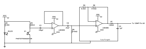
Hardware schematics
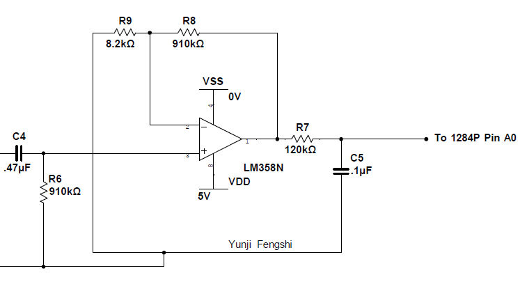
The IR Heart rate monitor sends an IR beam through the finger to the phototransistor to detect the change in volume in the blood flow.
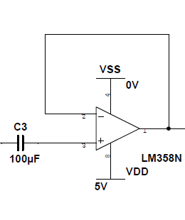
The coupling capacitor allows AC signals through while blocking DC signals, this lowers the signal to closer to the ground before amplification. The buffer stage is included to prevent the coupling capacitor from affecting the properties of the amplifying bandpass filter.
The amplifying bandpass takes the minimal signal from the IR emitter and phototransistor and amplifies it by a factor of 910kOhms/8.2kOhms, 111 times amplification. The bandpass filter was chosen to remove noise. The chosen capacitor and resistor values give a high pass cutoff frequency of 1/(2*pi*.47uF*910k) = 0.37 Hz, and a low pass frequency of 1/(2*pi*.1uF*120k)=13.3 Hz.
Hardware Testing/Problems Encountered
Each component of the heart rate monitor had to be thoroughly tested because it originally did not work at all. We tested the amplifying bandpass and the buffer by using the function generator and the oscilloscope, and comparing the result. We put in a sine signal into the buffer and received a sine signal on output. We did a frequency sweep on the amplifying bandpass and measured gain and the bandpass frequencies. It turns out the problem was that the system was extremely sensitive to finger placement and IR emitter and phototransistor alignment. Despite the bandpass filter, the phototransistor easily picked up noise from the lights. This was solved by building a fingertip clamp that lined up the finger, IR emitter, and phototransistor perfectly every time.
Another problem was that the amplifier that we used, the LM358N, could not reach it’s higher rail (5V), therefore the signal clipped around 4V. This turned out to not be a problem, as the clipped signal was extremely readable and resolved by our microcontroller software
Software
The code for determining heart rate is listed in ECG.c. This code depends on timer 1 interrupts. Timer 1 is initialized with a prescalar of 1024 and configured to compare match on ISR. We chose an OCR1A of 155. This combined with the frequency of the cpu (16Mhz) results in a sampling rate of 10 ms.
156 * (1024/16000000) = 0.009984 s.
We set up the ADC built into pin A of the ATmega1284p to calculate a value between 0 and 255 scaled between 0 and 5 volts.
To calculate bpm, at each interrupt, the ADC gives a value between 0 and 255. We keep track of the minimum and the maximum ADC input value sampled. Using these two values, an average threshold value is calculated, whenever the threshold is crossed on the falling edge of the pulse, we calculate the time between pulses as a delta. Using the delta, the beats per minute (bpm) is calculated by
60 / delta * 0.01.
In order to keep the value stable, we average the bpm over 20 bpm samples, and in order to output the value to port B in binary, we limited the heart rate to be between 0 to 255 or a uint8_t. The value for the bpm is updated every 2 seconds, and outputted on the LCD and portB.
Software Testing
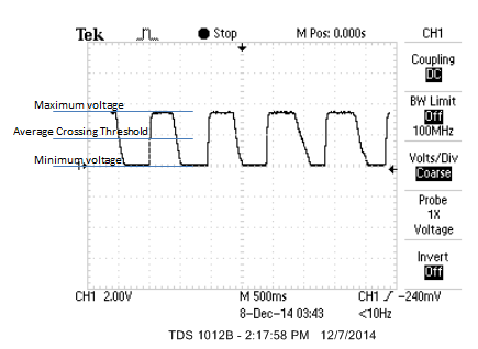
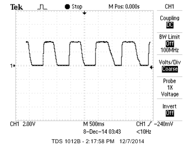
We tested the accuracy of ECG.c with a number of people using the oscilloscope by counting the number of pulses on the oscilloscope over a period of time. Above, there are 5 pulses in 5 seconds, resulting in 60bpm, which is what the 1284p measured.
Results
Chiptune Player
The chiptune player successfully generates four individual channels: pulse, triangle, noise, and delta modulation. After audio mixing through a hardware circuit, the resulting mono signal sounds as intended, with no waveform clipping present and the PWM carrier frequency blocked. Songs are played by the chiptune player with all four tracks in sync; that is, all four tracks are on beat and do not get ahead of one another by any perceivable difference.
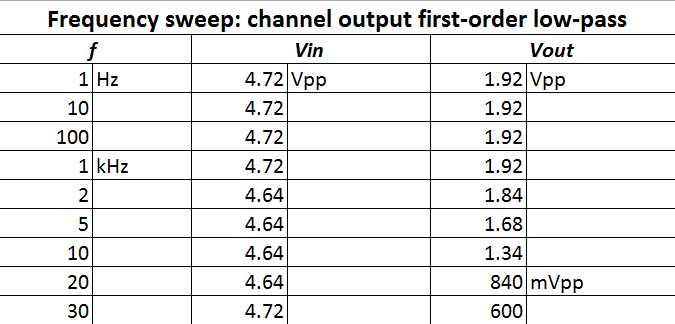
Below is a frequency sweep of the first-order active low-pass filter used to block the 62500 Hz PWM carrier frequency and pass note frequencies below 10 kHz:
As can be seen, the filter’s frequency response is 1/√(2) of the pass band gain at 10 kHz, as intended. This stage was eventually designed with gain rather than attenuation, necessary because the preceding summing amplifier stage attenuates the channel outputs significantly.
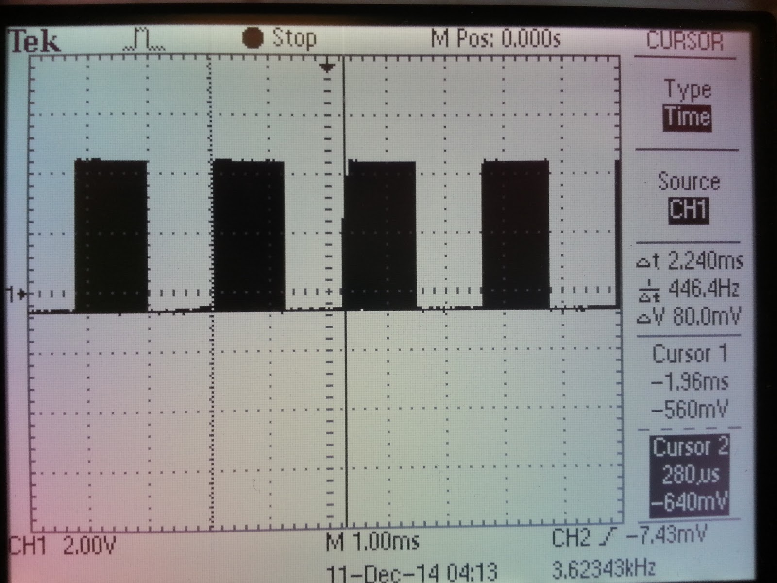
Here, we examine the output waveforms for each sound channel. The first oscilloscope waveform shows the pulse channel output at 50% duty cycle. The output is low for half its period and high for the other half, as expected. For the requested note frequency, 440 Hz, the expected waveform period is 2.273 ms. The observed period, indicated below by Δt = 2.240 ms, matches the expected value quite closely-- within 1.452%.
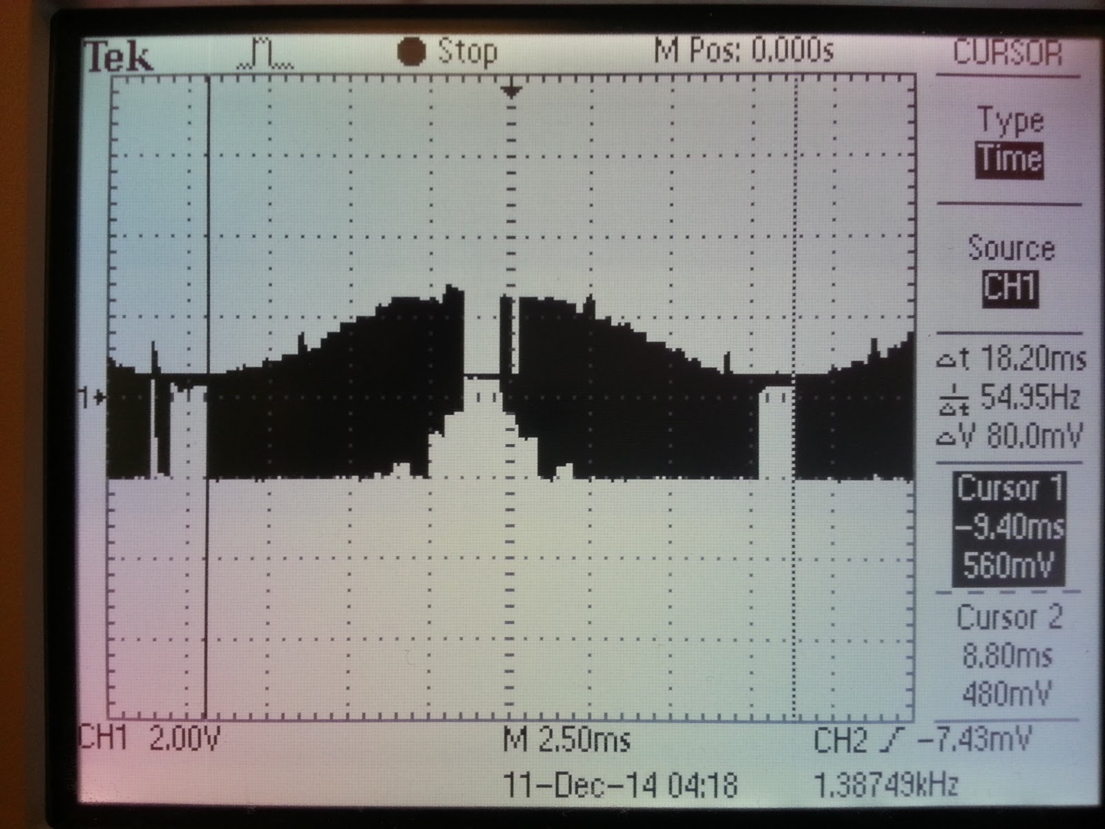
The second oscilloscope waveform shows the 4-bit triangle wave output. Note that the output only takes on one of 16 possible values, so the resulting waveform sounds harsh and looks rough. Increasing the resolution of the triangle wave results in a smoother sound, but the chiptune player was specifically designed to produce a 4-bit triangle wave in order to match the original NES’s sound. The resulting triangle waveform is as predicted, except for a dip to zero volts at the waveform’s peak. This unintended low-voltage spike actually creates a high-frequency artifact in the triangle wave output audible especially at low frequencies. The source of this problem was never found, but it is assumed to be a software problem, since the PWM outputs for all other three channels function correctly. However, the channel produces requested note frequencies just as accurately as the pulse wave channel above. For the requested note frequency of 55 Hz, the expected waveform period is 18.18 ms. The observed period, indicated below by Δt = 18.20 ms, matches the expected value within 0.1100 %.
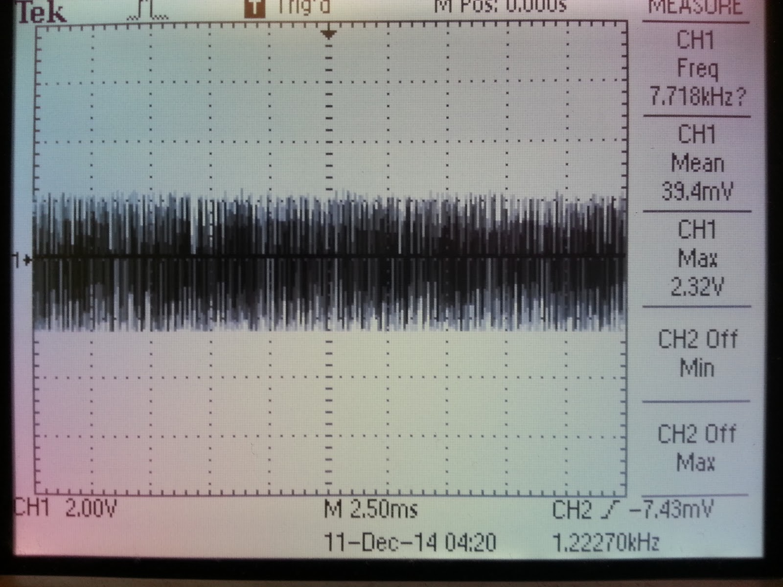
The third oscilloscope waveform shows the noise channel output. It is difficult to quantify how accurate this channel’s output is, but qualitatively the output waveform appears and sounds random. This confirms that the pseudo-random sequence of 32767 1-bit values produced by the noise channel is sufficiently random to represent white noise, and is appropriate for simulating high-hats and other percussion.
The fourth oscilloscope capture contains two waveforms: a heart pulse from the user on Channel 1 (top), and the output of the delta modulation on Channel 2 (bottom). The sample pattern being played consists of bass kicks at every other beat, interleaved with rim shots every other beat. The bass kicks result in the more salient impulses occurring with period 1.640 seconds, as in the bottom waveform.
The capture below furthermore illustrates the ability of the chiptune player to match playback tempo with the user’s bpm. As the chiptune player is in affective mode, the tempo of the song approaches the measured heart rate logarithmically. In the capture below, tempo and heart rate are effectively matched, such that the period between bass-kick impulses equals twice twice that of heart rate pulses. (Remember that in the pattern played below, bass kicks occur every other beat).
The success of the project can be confirmed by listening to the sound generated by the chiptune player. The following video introduces each of the individual sound channels. The music played is the first seven measures of the song “If I Ever Feel Better” by Phoenix.
Finally, the next two videos demonstrate the chiptune player playing two more fleshed-out covers: (1) “Wishing We Last Forever,” as performed by Faye Wong; and (2) “Bruises” by Chairlift.
As demonstrated, all four tracks are played in sync, with accurate note frequencies, note durations, and special effects.
As discussed in the Background section, the Timer0 overflow ISR for updating channel outputs is so computationally intensive that it must be split into two: the pulse channel is updated every other cycle, while the other three channels combined are updated on the alternating cycles. If not for this division of computation, the Timer0 overflow ISR does not execute in a short enough time, overlapping into the next timer overflow and producing note frequency audio glitches. However, with this alternating cycle scheme, every execution of the ISR completes well within 256 cycles. As well, the efficient execution speed of the ISR leaves sufficient spare cycles between triggers for the music parser to read through song information. The result is that all four tracks play with no perceivable time-lag between one another, even mid-measure. Eventually, however, incremental time-lags accumulate to result in a noticeable difference in time between tracks. This problem is especially noticeable when all four tracks are dense in terms of notes per unit of time, e.g. 32nd note rhythm. This issue is solved by syncing tracks at the end of each measure with a spinning wait, as explained in the Chiptune Player Implementation Details section.
Heart Rate Monitor
Our heart rate monitor calculates the time between pulses on the first pulse, therefore is extremely quick to calculate values. However to smooth the output beats per minute, we used a running length-20 averaging filter.
As shown in the testing section above, the heart rate monitor is extremely accurate, and tested on a variety of people. The sound output is also extremely accurate in terms of frequency, tested with a guitar tuner.
Since our project is for human use, we put safety at the highest priority. The project has low voltage and low current and does not have any safety concern. The project was assembled with clean circuitry and minimal exposed wiring to prevent shorts. We used 9V battery power instead of a power supply so the user had no direct connection to the 120V electrical grid. When programming the microcontroller, we used a laptop running on battery power.
Other than producing sound that may be picked up by microphones used by other groups, our design does not interfere with other group’s designs. We did not pick up any noise during normal operation.
We designed our fingerclip for the heart rate monitor to be easy to use, the user only needs to insert their finger with minimal adjustment. The clips for the GSR are attached by velcro and easily adjustable. The sound output component is also very easy to use with a user-interface to select songs.
Conclusion
Results, expectations, further work
As discussed in the Results section, The chiptune player successfully generates four individual channels: pulse, triangle, noise, and delta modulation. After audio mixing through a hardware circuit, the resulting mono signal sounds as intended, with no waveform clipping present and the PWM carrier frequency blocked. Songs are played by the chiptune player with all four tracks in sync. In affective mode, playback tempo is adjusted to match bpm measured from the user.
Originally, the chiptune player was intended to emulate the NES APU exactly, such that it can read .NSF song information ripped directly from NES cartridges. The rationale was that a wealth of professionally-composed and nostalgia-inducing music already exists for this type of sound, so implementing an .NSF player would extend the capability of the chiptune player to play a nearly unlimited number of high-quality songs. However, the task of creating an .NSF player was determined to be too difficult for our current level of preparation: .NSF files are essentially structures containing instructions for the NES CPU, i.e. write to certain registers, set specific flags, trigger some interrupt. In order to implement a .NSF reader, the NES CPU itself would need to be emulated in part, which is a complex task.
Instead, our implementation relies on an original scheme for hardcoding music and parsing that information. This approach is similar to the original intent described above in that the chiptune player has the ability to play an unlimited number of songs. However, the task of hardcoding music is quite time-consuming for people like me who aren’t well-versed in musical notation and transcribing complex rhythms. Still, the music-encoding scheme was designed to be as similar pen and staff paper as possible, so perhaps a more skilled musician would be able to transcribe songs in much shorter amounts of time.
Aside from .NSF playing functionality, expectations were matched by the results. The successful design of the chiptune player can be confirmed simply by listening the hardcoded songs it plays. Although time-consuming, hearing songs that you have hardcoded play back as intended is quite rewarding. After encoding basic song information such as note frequencies and note durations, there is some room for creativity at the interpretation level; for instance placing short silences between notes to create more syncopation versus smooth legato between notes, and adding in special effects such as duty-cycle modulation and frequency sweeps.
The heart rate monitor functions exactly as expected, as stated in testing, we measured a number of people’s heart rates using the 1284p as well as the oscilloscope. While we were expecting a more steady value without the need for averaging, this is because the average crossing threshold changes often.
Apart from implementing an .NSF player, other ideas for further improvement include: implementation of a second pulse wave channel, identical to the first. This allows a fifth voice that significantly increases the possibilities for harmony, or special effects. For instance, one technique used by chiptune composer is to play the second pulse wave channel at identical pitches to the first channel, only slightly time-delayed and much softer in volume. The result is an echo-like or reverb effect.
Another idea for future work is to implement a special command to play a chord on a single channel. Since the NES is limited to five voices total, the harmonic textures that can be created are quite limited. One way that chiptune composers have overcome this limitation is to repeatedly change one channel’s frequency setting discretely between three or more notes, playing an arpeggio or broken-up chord. If executed quickly enough, the resulting sound approximates a single, unbroken chord.
Standards
A standard used was the implementation of communication between the 1284p and the computer through the use of UART, used in conjunction with the RS-232 communication standard. This was used for debugging, but removed from the final code. Connecting with the computer to program the 1284p required the use of SPI, Serial Peripheral Interface Bus. Programming the MCU uses the SPI bus with the following logic signals: SCLK, MOSI, MISO, and SS.
Another standard followed is ISO 532:1975. This standard “specifies two methods for determining a single numerical value of a given sound, the first method is based on physical measurements, such as spectrum analyses in octave bands, the second method is based on spektrum analyses in one-third octave bands.” This gives the acceptable ranges for sound in relation to human beings.
Intellectual Property Considerations
We used lcd_lib.c and lcd_lib.h from scienceprog.com, which is distributed under the GNU Public License.
While everything was our own design, we did get inspiration from Heart Rate Display LED T-Shirt, a ece 4760 final project from spring 2010 for detecting average crossing on the falling edge. We did improve upon their algorithm for better accuracy.
As explained in the High Level Design section, the Nintendo and Nintendo Entertainment System trademark are owned by Nintendo. Our emulation of the NES sound chip is inspired by the NES, but is our own design and does not infringe upon Nintendo’s copyrights. In designing a sound similar to the NES, community-produced documentation and specifications available on the web were used.
The chiptune player contains original covers “Bruises” by Chairlift, “Wishing We Last Forever” as performed by Faye Wong, and “If I Ever Feel Better” by Phoenix. The original compositions are properties of their respective artists and are used solely for demonstration purposes and not personal gain.
Ethical Considerations
The code of ethics from IEEE were consistently followed for this project. We accept responsibility in making decisions consistent with the safety, health, and welfare of the public, and to disclose promptly factors that might endanger the public or the environment. Our heart rate monitor does not endanger the public and was built with safety in mind, and our chiptune player is within the range of acceptable human hearing. We avoided real or perceived conflicts of interest. We were honest and realistic in stating claims or estimates based on available data when creating the website. As undergraduate students, we were not exposed to bribery, but we will continue to reject bribery in all its forms.The report serves to improve the understanding of technology; its appropriate application, and potential consequences. As we received help and advice from Professor Land and the TA’s, we sought, and accepted honest criticism of technical work. We also promise to acknowledge and correct errors, and to credit properly the contributions of others, by giving credit to our sources of inspirations. There was no discrimination or injury in the creation of this project. Also through assisting each other with the project, we assisted each other in our development.
Appendices
Code Listing
ECG.c
Chiptune.c
Schematics
Chiptune player schematic
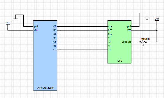
LCD connection with ATmega1284p
Heart rate monitor Circuit
Parts List and Cost
Component | Unit Cost | Source | Quantity | Cost |
White Board | $6.00 | ECE 4760 Lab | 2 | $12.00 |
Power Supply | $5.00 | Digikey | 2 | $10.00 |
PC Board | $4.00 | ECE 4760 Lab | 2 | $8.00 |
Mega1284P | Sample | Digikey/Atmel | 2 | $0.00 |
LCD | $8.00 | ECE 4760 Lab | 2 | $16.00 |
Header Pins | $0.05 | ECE 4760 Lab | 68 | $3.40 |
10k Ohm Trimpot | $0.50 | ECE 4760 Lab | 2 | $1.00 |
Resistors | $0.00 | ECE 4760 Lab | 30 | $0.00 |
Capacitors | $0.00 | ECE 4760 Lab | 10 | $0.00 |
IR Emitter | $0.00 | ECE 4760 Lab | 1 | $0.00 |
Phototransistor | $0.00 | ECE 4760 Lab | 1 | $0.00 |
LM358N Op-Amp | $0.48 | ECE 4760 Lab | 4 | $1.92 |
M0520 Speaker | $8.99 | Lenovo | 1 | $8.99 |
Wiring | $0.00 | ECE 4760 Lab | 8 ft | $0.00 |
Total: | -- | -- | -- | $61.31 |
Division of Labor
Yunji Fengshi | Scott Zhao |
Heart rate monitor Hardware Design/Assembly | Chiptune Player Hardware Design/Assembly |
GSR Hardware Design/Assembly | Chiptune Player Software Design |
Software Design for Biosensor 1284p | Music transcription |
Hardware Testing | Hardware Testing |
Integration | Integration |
Final System Testing | Final System Testing |
References
Datasheets:
Vendors:
Referenced Code/Designs:
NES APU Sound Hardware Reference
2A03 Sound Channel Hardware Documentation
Background:
An Article on Affective Computing
Acknowledgements
We would like to thank Bruce Land for teaching one of the most hands-on, educational courses at Cornell, and for his guidance during the project. We would also like to thank the lab TAs for their assistance in debugging and for staying extra hours to allow us to work longer.