For our final project, the goal was to design a system that allowed one RC car (primary) to autonomously track a target on a separate, manually-controlled RC car.
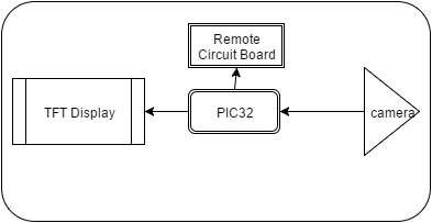
Using a PIC32 microcontroller, a camera that is attached to the front of the autonomous car communicates images of the target to the microcontroller. The PIC32 then does some image processing to determine whether the car should speed up, slow down, turn left, or turn right in order to maintain an acceptable distance away from the target. On the back of the car is a TFT LCD screen that displays the direction of the target relative to the acceptable location based on the autonomous car. The primary car was controlled by connecting the circuit board of its remote to the PIC32 microcontroller.
>High Level Design
>Hardware Design
>>Remote Controller
>>Camera
>Software Design
>>Car Movement
>>Camera
>>Vision Algorithm
>>Tracking
>>TFT Display
Conclusion
Appendix
>>Code
>>Schematics
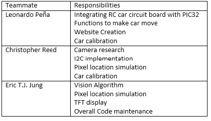
>>Teammate Responsibilities
>>Parts List
>>References
The project idea was originally conceived for a quadcopter: using a vision tracking system to pilot the quadcopter to follow an object, perhaps for recording videos of it. We thought it would be cool if a system like ours could be used to record extreme sports from 3rd person’s perspective, rather than 1st person, which we have with GoPro. However, building quadcopter is very complicated, and we wanted to focus on the vision tracking part, so we changed the vehicle to an RC car.
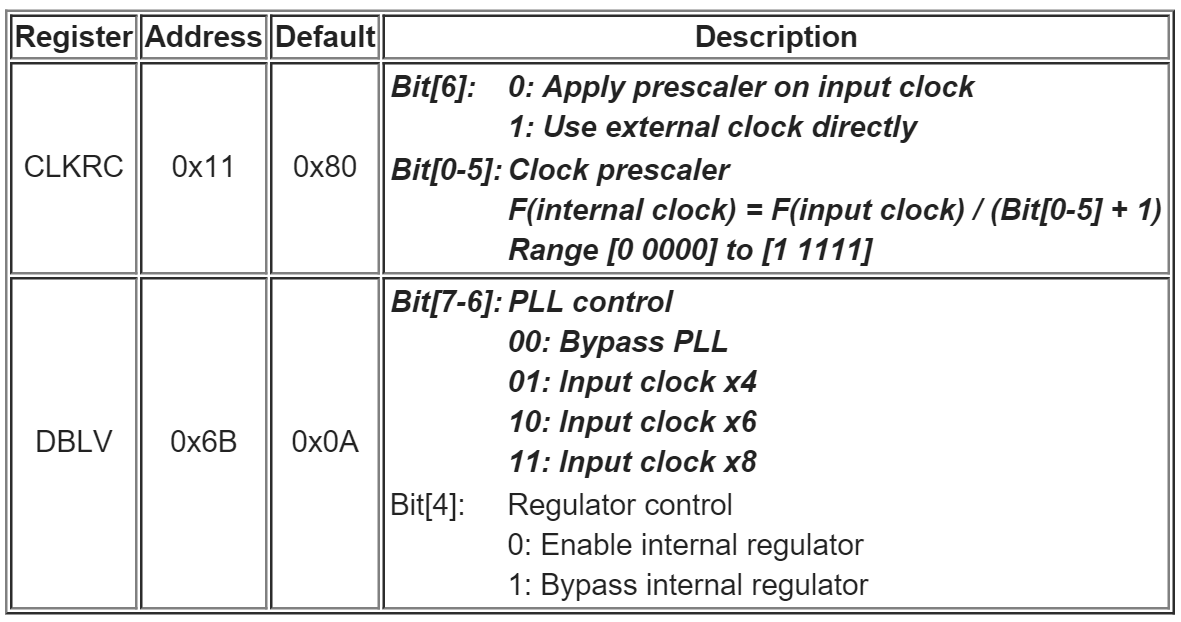
Our system consists of mainly 3 parts: car/remote, camera, and vision tracking algorithm. The OV7670 camera is integrated with the PIC32 by passing a clock signal to the OV7670 and then matching the PIC’s I2C protocol with the camera’s internal SCCB protocol. This sets up the PIC as the master device and the OV7670 as the slave. The most difficult part of this integration would be setting up the SCCB protocol to properly receive data from the OV7670. Once the protocol is set up, the camera can be set to process its own image data and transfer at a user defined frame rate and image quality. Another difficult aspect of integrating this camera is the large amount of data to be transferred and processed, as the PIC does not have a lot of on board memory. For this project, to minimize the amount of data being processed, we would have set the camera to send images at 20 fps in the QCIF (176x144) video format as opposed to the default VGA (640x480) at 30 fps.
Using the image data passed from the camera, we locate the markers on the target to be used for controlling the car. The target is a very simple design, with 3 sizeable dots on a white background, laid out in a triangle. First we use absolute thresholding on the image with low threshold to filter out most of the background, giving us a segmented binary image. We then perform morphological filtering on the segmented image, with a opening filter. Opening filters first erode then dilate an image with a given kernel, having the effect of filtering out all parts of a region that cannot fit the kernel, such as in Figure X, as well as all “objects” smaller than the kernel. We use a circular kernel about half the size of the markers on the image at the desired follow distance, so that all the noise in the background is filtered out, but we still keep the markers, since we assume that the vehicle’s distance with regard to the target is fairly limited, so the markers should not appear too small on the image.
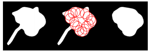
2D opening example
Once filtering is done, we should have segmented image of the targets alone. To locate the centers of the targets, we iterate vertically down and find two rows with local maxima. Then we find min and max of one object for first row, and a pair of min and max, one for each object, for second row. Lastly, we average the min and maxes, giving us 3 pixel locations for center of the markers.
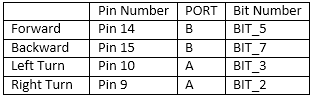
The 3 pixel locations from the vision algorithm is then used to move the car. We use the middle high point for orientation and the distance between two bottom points for distance measuring, and steer accordingly, trying to keep the target at center and at a certain distance. Moving the car is done by “hijacking” its remote controls. The remote is of a very simple design, using just 4 active-low digital buttons to control the car going forward, backward, left, and right. We used the PIC32 ports as outputs and output corresponding commands by setting and clearing the ports.
Hardware Design
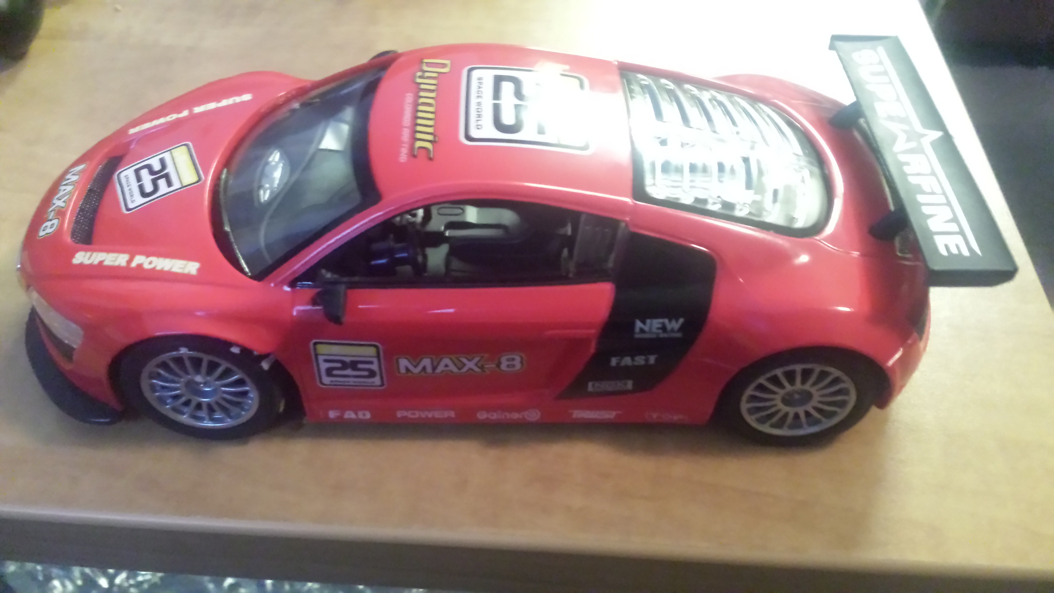
To create this project, we needed two RC cars. One RC car and its remote controller was left in its original, retail state. This was the car that was going to be controlled manually and followed by the modified RC car. The other RC car was the primary car and had its remote modified to be controlled by the PIC32. This was the car that was going to be following the first RC car.
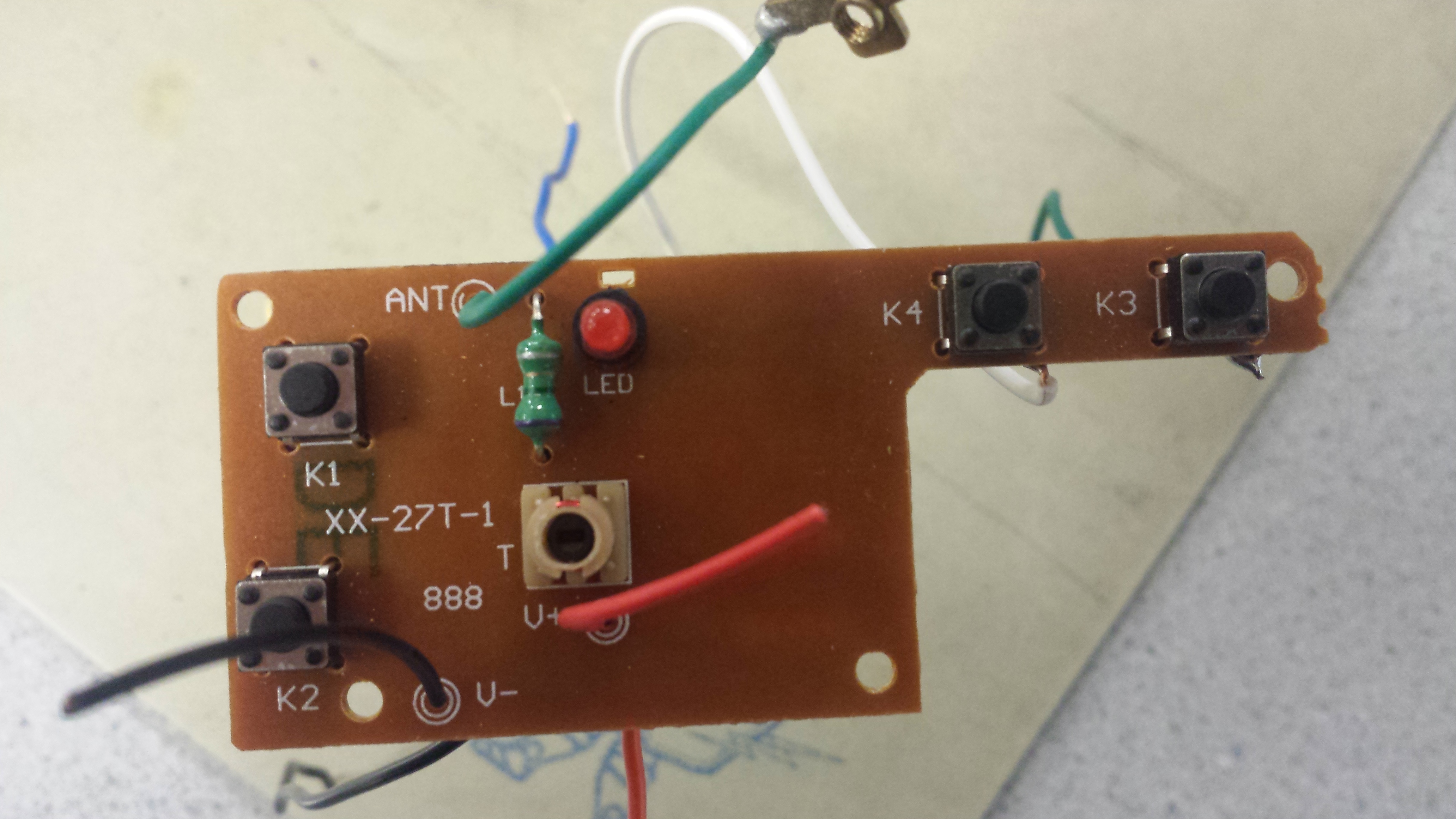
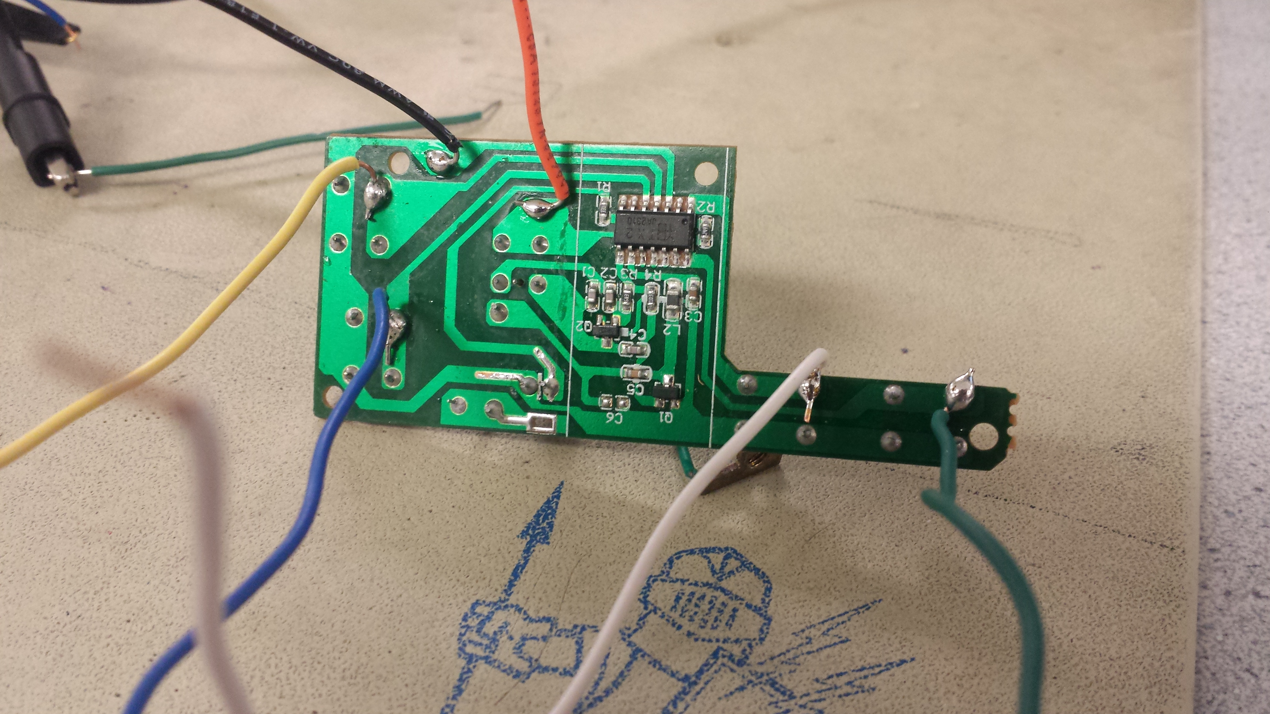
When we opened up the remote and took out the circuit board, we realized that the implementation was a little weird. When powered, all of the switches were set to high. Each of them had to be grounded in order to make it operate. To make it easier on ourselves, we soldered wires onto the ground connections in order to be able to connect them to the PIC32 ports. After connecting the Vdd and ground pins on the circuit board to the PIC32, we set four pins to be digital outputs and assigned them to a specific switch. To activate each function, we clear the output (set to logic-low) of the corresponding output pin. This drives the connection to ground and activated the switch.
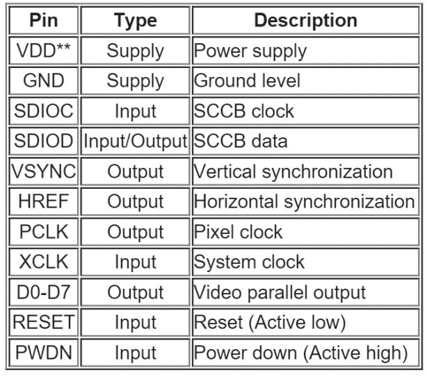
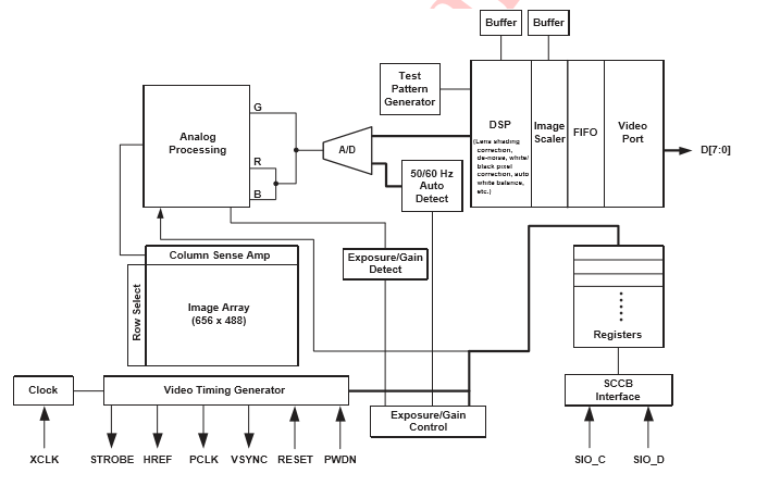
The OV7670 is a low cost image sensor and DSP that can operate at up to 30 fps and 640 x 480 ("VGA") resolutions, equivalent to 0.3 Megapixels. The image data can be pre-processed by the DSP before sending it out. This preprocessing can be configured via the Serial Camera Control Bus (SCCB), which operates basically like I2C protocol. The OV7670 can be operated safely between 3-3.6V so we powered it with the MicrostickII provided in lab, supplying 3.3V to VDD. All the I/O pins on the OV7670 were supplied 3V.
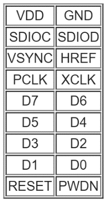
The OV7670 has a 9x2 header as described below:
Software Design
The software in this project was all handled using the PIC32 microcontroller.
To control movement of the car, six functions were implemented: moveRight(), moveLeft(), moveForward(), moveBackward(), moveStraight(), and stop().
Each of the functions first deactivated the opposing direction, if it had one, and then proceeded to activate the corresponding direction. For instance, moveRight() would first call mPORTASetBits(BIT_3) in order to make sure the car was not also turning left and then call mPORTAClearBits(BIT_9) to move right. These functions would also display the corresponding directions on the TFT display by filling the triangles.
It is important to note that not all of these functions are mutually exclusive. In fact, moveRight() and moveLeft() only turn the wheels of the car and would be virtually useless without being used in conjunction with moveForward() and moveBackward(). moveStraight() was used to ensure that all of the wheels are facing straight while the car moved forward.
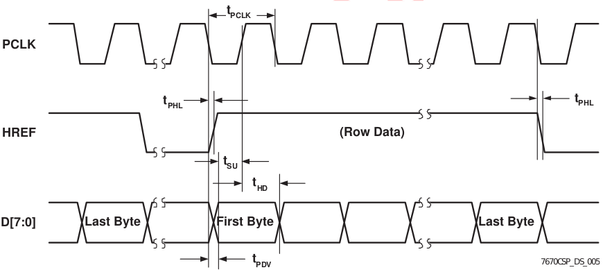
The OV7670 sends data in a parallel synchronous format, so to receive any data, we must supply a clock signal to the XCLK pin. According to the datasheet, the clock frequency must be between 10 and 48 MHz, so we went with 20 MHz, since our system clock is set to 40 MHz. This way, we simply gave a pre-scalar of 2 to the system clock to output to the OV7670. Once the clock signal was applied to the XCLK pin, the OV7670 started driving its VSYNC, HREF, and D0-D7 pins. It also automatically created a PCLK signal, which controlled the framerate of the image capture. By default, this PCLK signal had the same frequency as XCLK. From the datasheet, a PCLK of 24MHz corresponds to 30 fps and 12 MHz corresponds to 15 fps, so ours operating at 20 MHz gave us 20 fps. We were okay with this loss of framerate as we wanted to minimize the about of data being processed. The D0-D7 pins were sampled at the rising edge of PCLK and only while HREF was high. The rising edge of HREF signaled the start of a new line, while the falling edge was the end of a line.
The OV7670 uses SCCB protocol as opposed to I2C, which is already implemented on the PIC32.
SCCB is very similar to I2C as it has a master device and slave devices.
In this project, the MicrostickII is the master and the OV7670 is the slave.
For SCCB protocol, there are 4 possible signals for communication, SCCB_E, SIO_C, SIO_D, and PWDN.
From the SCCB Specification Sheet:
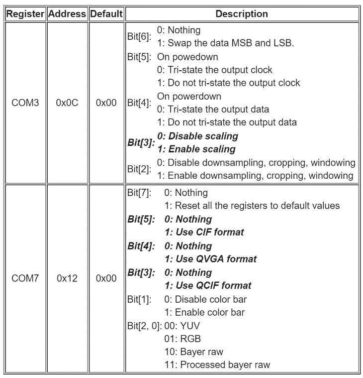
Once the OV7670 was connected and SCCB was setup, we were able to make modifications to the data we were receiving. As mentioned above, full 640x480 VGA at 30 fps would be far too much data to process for our purposes. To make image processing simpler, we operated at only 25 fps and changed formats from VGA to QCIF (176x144). This was easily done by modifying the corresponding COM ports as described below.
The algorithm is quite simple to implement. To implement absolute thresholding, we iterate over each image, and if the pixel value is lower than the threshold, we mark it as object (1), and otherwise as background (0).
Morphological filtering is also quite simple. We first erode by iterating over each pixel in the segmented image, AND’ing it with all surrounding pixels located accordingly to the kernel with regards to current pixel. We then dilate by doing the same, but instead using OR in place of AND.
We find the centers of the circle with a heuristic search. We iterate vertically down the segmented and filtered image, and starting from first row that has valid (1) pixels, count the number of valid pixels in each row. We save the first row that has decreasing number of valid pixels. We then iterate down till the rows are empty, then down again until we find the first row with valid pixels, finding the center row using the same approach as above.
First row contains only 1 marker, so we can mark where the valid pixels begin and end average the two to get x location of the center. Second row contains 2 markers, so we first mark beginning and end of a set of valid pixels, then find the next beginning and end of a set of valid pixels, using the the two pairs to find x locations of the two centers. The algorithm returns these 3 centers in order of left (low), center (high), right (low).
Using the 3 locations from the vision algorithm, we can determine the movement of the car. We set 3 thresholds, one for midpoint, one for following distance, and one for reversing distance. We first check the forward/backward movement by using the distance between left and right points. If the distance is greater than the reverse distance, the vehicle is too close to the target and needs to reverse. If the distance is less than the following distance, the vehicle is too far and needs to move forward. If neither, the car is at the desired distance of the target.
We then check for orientation using location of the center marker and the midpoint threshold. If location is less than the threshold by more than 2, the target is to the left, if the location is greater than the threshold by more than 1, the target is to the right, and if neither, the target is considered in front of the vehicle. If moving forward and target is to the right, we also turn right, and if moving forward and target is to the left, we also turn left. If moving backward and target is to the right, we turn left, and if moving forward and target is to the left, we turn right. If the vehicle is not moving, changing the directions won’t affect much, as the vehicle is not moving and can’t orient itself.
The TFT display was the easiest to implement as it had all of the same pin connections as Lab 3. It drew four triangles centered around a circle. When the car moved in one or two of the four directions, the corresponding triangle(s) would fill up white. When the car was moving forward, the circle turned green; when moving backwards, it turned blue; and when not moving, it would stay red.
Unfortunately, our project was turned out less than stellar and did not meet our expectations. The biggest problem was that we never had a functional camera to implement the vision algorithm with. The first camera we ordered ended up being incredibly small; too small, in fact, to even use it. The second camera that we ordered immediately after never came, probably due to being held up in customs.
Understanding this problem, we decided to do as much as we could while we waited for the camera to arrive. The majority of the weeks was spent getting the car to function how we wanted it to and on doing research on both the computer vision algorithm and the I2C protocol for the camera. Additionally, we played with the idea of adding a separate controller for the car by either using a keypad or utilizing a keyboard and UART serial communication. We thought that implementing it by connecting it directly to the PIC32 was pointless, as it went against the original idea of having the microcontroller on the car itself. We then thought it would be a good idea to implement it using a radio transmitter, but it would require an extra microcontroller and other hardware that we had no time to get, so we couldn't do that either.
For the demo, instead of showing up with nothing, we hardcoded a stream of pixel-location arrays to show that our movement algorithm was working. The idea behind this was that we would simulate the output of the camera post-processing to show that the rest of the project was working.
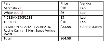
Note: This does not include the cameras since we did not end up using them
http://embeddedprogrammer.blogspot.com/2012/07/hacking-ov7670-camera-module-sccb-cheat.html
http://www.voti.nl/docs/OV7670.pdf
Back to top