A project by Erissa Irani, Rohit Jha, and Amanda Pustis
Introduction
The purpose of this project is to create a wearable device that helps users correct their posture in order to alleviate back pain and maintain a healthy lifestyle. We created a posture monitor because of our interest in health and fitness. We designed our circuit using the PIC32 microcontroller, flex sensor, vibration motor and TFT LCD. We attached the flex sensor and vibration motor to the lower back of a compression shirt that is worn by the user. The microcontroller uses the output of the sensor to determine if the user is in poor posture and sends a signal via the vibration motor accordingly. We also included an interactive display that allows the user to calibrate the sensor according to his or her good posture, gives the user a visual indication of when the user is in bad posture as well as keeps track of how many times the user slouches. Our goal is to design an easy-to-use product for those who want to better their posture during everyday tasks, such as working at a desk or sitting in class.
High Level Design
Rationale
One day over the summer, a member of our team felt a back ache while sitting at her desk all day during a summer internship. This back pain caused by slouching all day led her to think about creating a wearable device to detect poor posture and remind her to sit up straight. She brought this idea to the group at the beginning of the semester, and together we designed and constructed a posture corrector.
Logic Structure
The logic of the program is as follows: A welcome screen prompts the user to press a button twice in order to calibrate the device. The display tells the user to hold still in good posture as the loading bar fills across the screen; once calibration is complete, the user can press the button once to see a displayed outline of a human back with a vertical green bar along the spine representing the flex sensor on the user’s back. This bar maintains a green color until the flex sensor’s value falls below the calibrated threshold of good posture for that user, at which point it turns red to indicate poor posture. In addition to the visual signal, the vibration motor turns on, providing a physical indicator for the user to immediately correct his or her posture. Furthermore, by pressing the button, the user can toggle between this screen and a counter screen which tracks the number of instances the user experienced poor posture.
Patents
There are products similar to ours that are patented, such as the Advanced Posture Corrector1 which uses variable musical signals and vibrating signals to notify the user of poor posture, causing the user to return to proper posture. Another device that is similar to ours is Lumo Lift2 which is a small wearable device that gives the user a slight vibration signal when it detects slouching. Lumo Lift also has a smartphone app that helps the user track posture hours, steps, distance and calories burned.
Hardware & Software Tradeoffs
The main focus was placed on determining the number of vibration motors and flex sensors needed to detect poor posture. We found that adding more flex sensors did not necessarily give us better results than using only one to detect slouching. After testing the vibration motor, we decided that one vibration motor provided a strong enough signal to the user to indicate poor posture. Due to the decrease in hardware components, we added more features to the the user interface such as a calibration mode and multiple screens that show user information.
Hardware Design
Overview
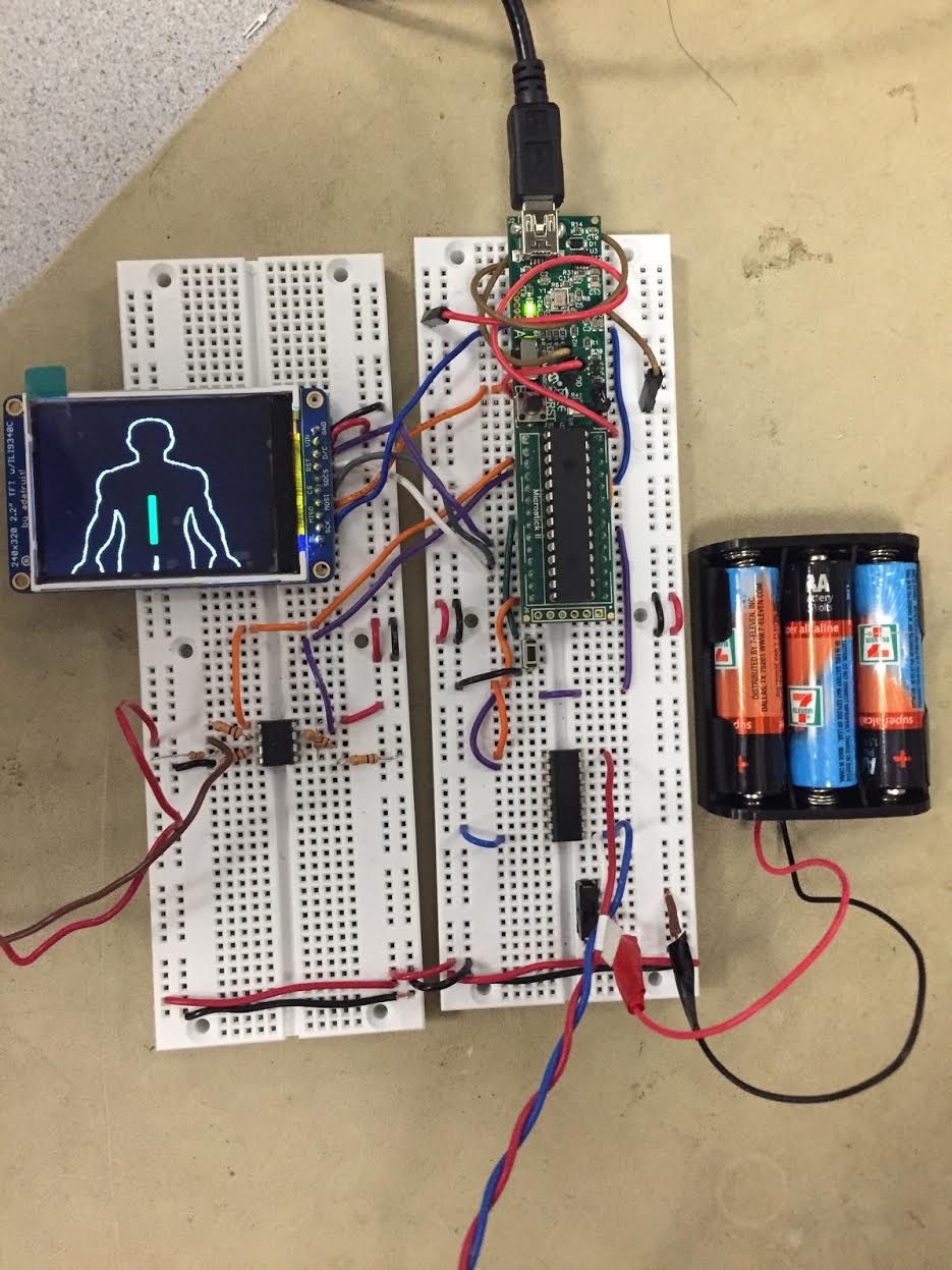
The hardware components which include the flex sensor, vibration motor, and LCD, revolve around the PIC32 microcontroller. The final hardware design is shown in Figure 1.
Figure 1: Final hardware design- the red and blue twisted wires at the bottom attach to the vibration motor, the red and brown twisted wires on the left connect to the flex sensor
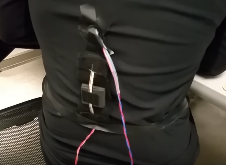
The flex sensor and vibration motor are attached to the compression shirt by velcro and electrical tape as shown in Figure 2.
Figure 2: The flex sensor (bottom) and vibration motor (top) attached to the lower back of the user
Our device is constructed as follows; the flex sensor is connected to the PIC32 microcontroller via an analog input pin, the PIC32 uses this reading to toggle the vibration motor according to the threshold set after calibration, and the vibration motor is attached to the PIC32 as an output on one of the I/O pins and is powered by an external power supply.
Flex Sensor
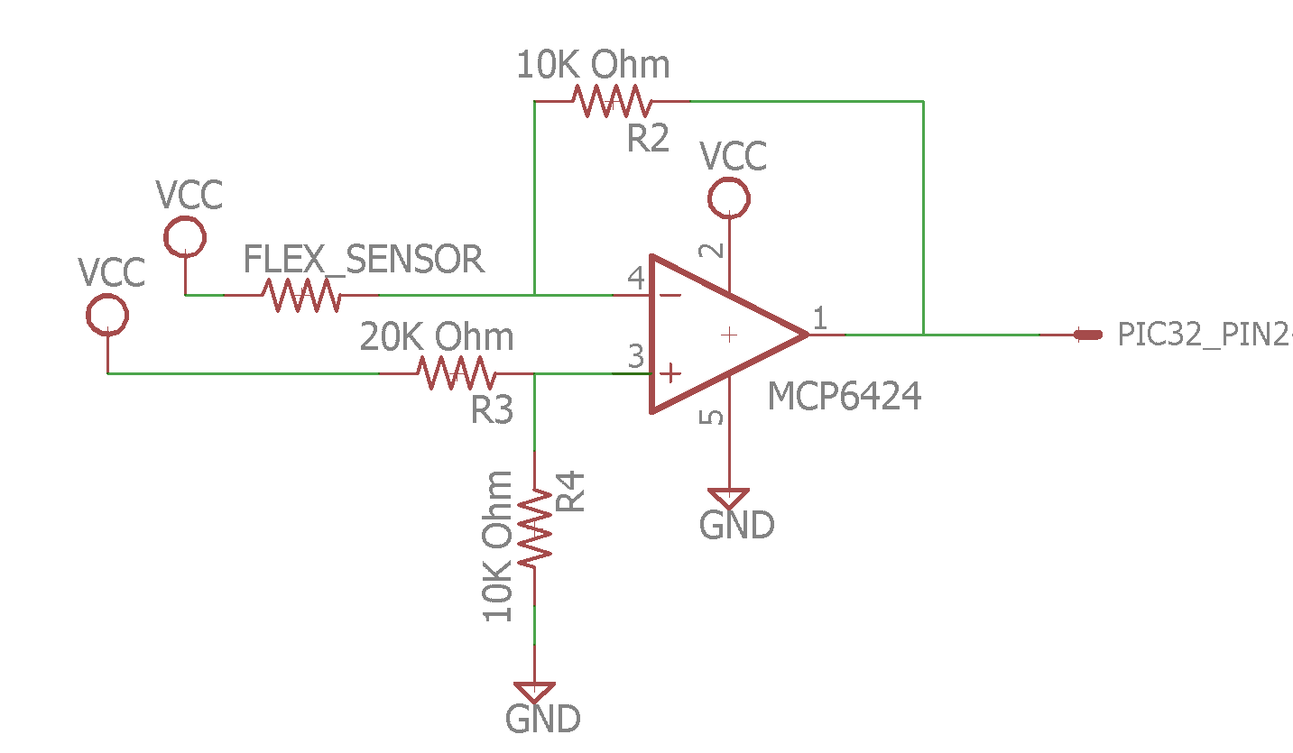
Our project consists of one Flex Sensor 4.5” from Adafruit. As the sensor bends, the resistance across the sensor increases. Initially, we connected the sensor directly to an analog pin of the PIC32, but as we tested it on the user’s body, we came to the conclusion that the sensor was not sensitive enough to detect back bends. To solve this, we created a circuit using the MCP6242 op amp, shown in Appendix E Figure 3, to increase the sensitivity of the flex sensor, thus increasing the range of values read from the sensor.
The Vcc connections are powered by the PIC32 at 3.3V. We configured pin 2 of the PIC32 as an analog input (AN0) and connected the output of the op amp to this pin. We also used the internal analog to digital converter (ADC) of the PIC32 to acquire and read the output of the flex sensor circuit. To ensure that our circuit increased sensitivity, we displayed the readings from the flex sensor onto the LCD. Before adding the op amp circuit, the flex sensor outputted a range of values from 80 to 120, but once the op amp circuit had been implemented, the range of values read from 30 to 170. We tested this on the user’s back and observed a great improvement; the sensor was able to detect slight bends in the back.
Another problem we faced with the sensors was detecting slouching on multiple points on the user’s back. Originally, we planned to have multiple flex sensors on the user’s shoulders, neck, and upper and lower back, but as we tested the sensor on each of these locations, it became evident that the lower back position gave us the most consistent and accurate reading. Therefore, we decided to place the 4.5” flex sensor vertically on the lower back along the spine of the user.
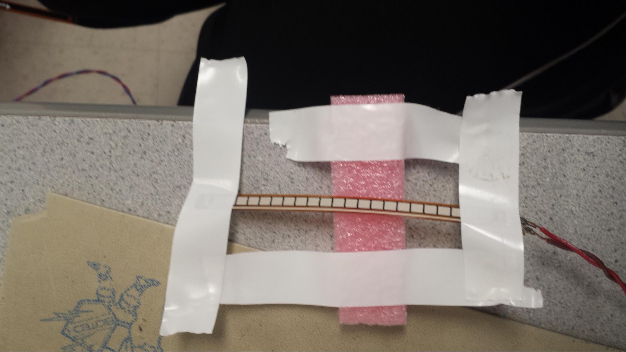
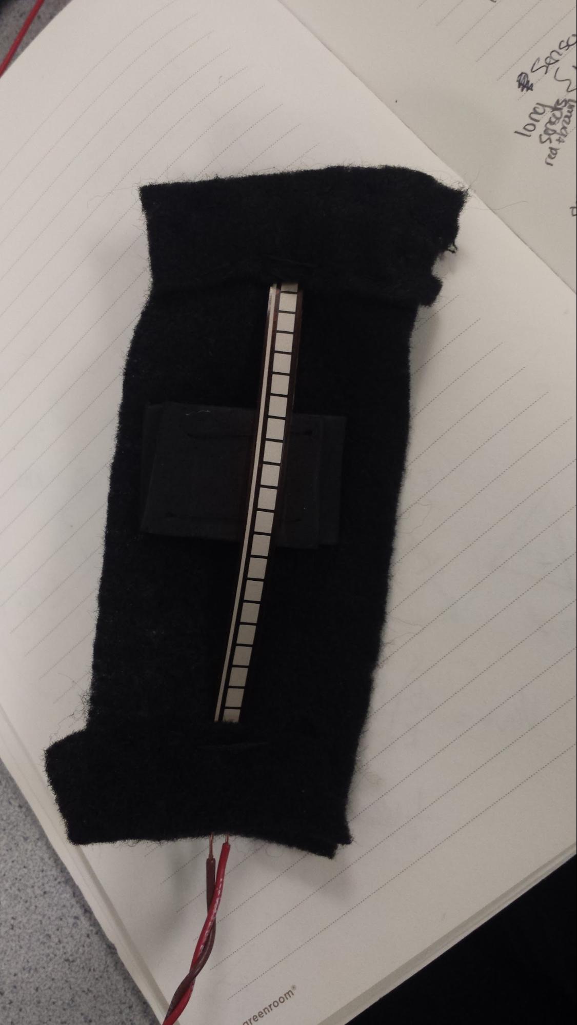
We also did some adjusting once we found the optimal location for the sensor. Placing the sensor directly onto the user did not give consistent readings nor did it detect slouching, so after many trials and errors, we found that the sensor worked best if we bent it slightly using foam pieces under the center of it and securely fastened the ends of the sensor to the shirt. Figures 4 and 5 show how we implemented this.
Figure 4: How we positioned the foam under the sensor
Figure 5: Used felt to secure the ends of the sensor and keep it slightly bent
Figuring out how the user would wear our device was another issue. At first, we thought that an adjustable runner’s vest would be able to fit most and would allow the user to wear the posture corrector over clothing. Unfortunately, the vest we wanted to use was too loose, thus prohibiting the flex sensor to detect poor posture. Instead of the vest, we used a compression shirt and attached the sensor to it and although this provided better results, we no longer had a ‘one size fits all’ wearable device.
Pushbutton
In addition to the flex sensor as an input to the PIC32, there is also a pushbutton. This button is connected to the PIC32 via pin 7 as a Port B digital input. With this button, the user is able to navigate from the home screen to calibration mode. Once calibration is done, the user can toggle between two screens on the LCD; one that gives a visual cue for when the user is in poor posture, and another that keeps track of how many times the user experienced poor posture. This interactive portion of our device gives it greater usability as well as allows users who cannot feel the vibration from the motors another way to know that they are in poor posture.
Vibration Motor
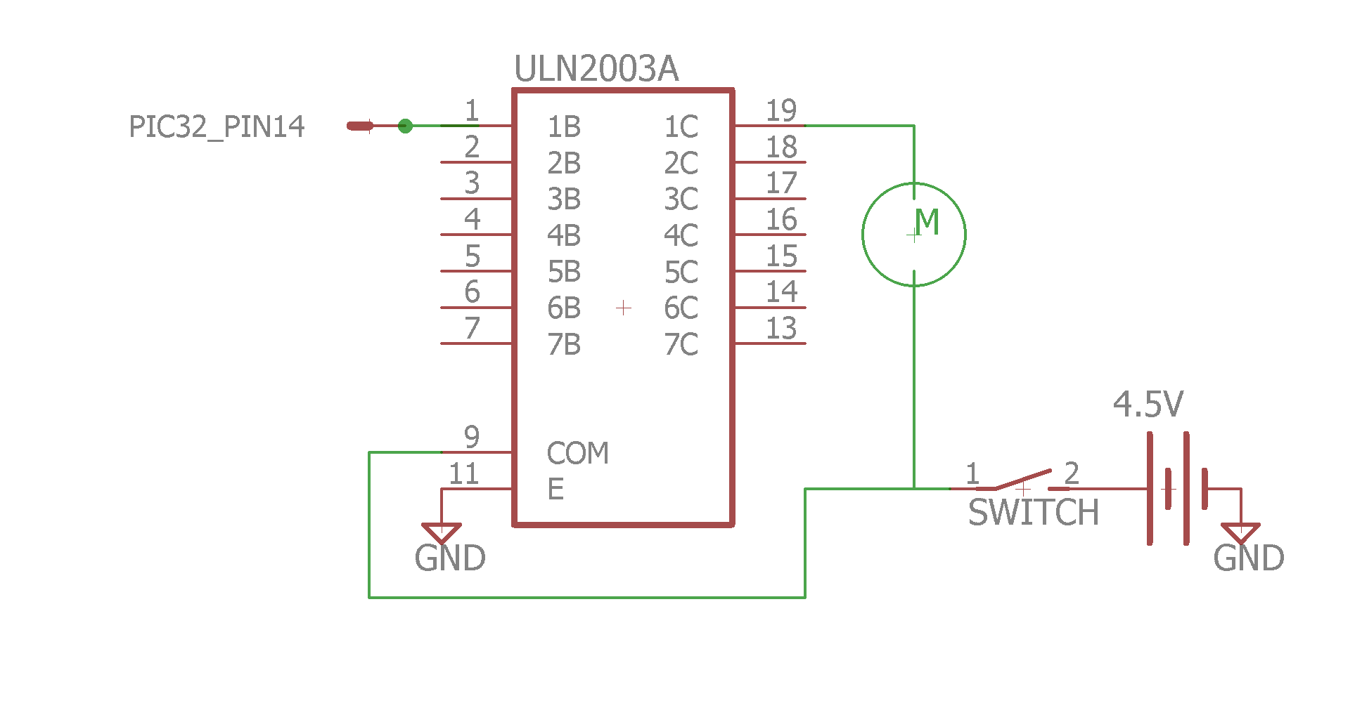
We used the Vibrating Mini Motor Disc from Adafruit as a way to signal to the user that he or she is exhibiting poor posture. According to the specifications, at 3V the motor draws 60 mA, which is more than any one output pin on the PIC32 can supply. To remedy this, we used the ULN2003a driver (Appendix E Figure 6) to supply enough current to the motor. We also used an external power supply that consisted of three AA batteries providing 4.5V to the motor because the PIC32 did not supply enough power for the motors as well as the LCD.
Another challenge we faced was having multiple motors connected and run simultaneously. Although we did not get this to work because it drew too much power, we modified our design to use one sensor and one motor. We attached the motor to the shirt, above the flex sensor and along the spine, which provides the user with an uncomfortable sensation, causing the user to return to good posture.
TFT LCD
We provided an interactive display using the TFT LCD. We connected the pins as follows;
SCK: connected to pin 25, RB14 on the PIC
MOSI: connected to pin 22, RB11 on the PIC
CS: connected to pin 11, RB4 on the PIC
SDCS: left unconnected as we did not use the microSD card for this
RST: connected to pin 12, RA4 on the PIC
D/C: connected to pin 9, RA2 on the PIC
VIN: connected to 3.3V supply
GND: connected to ground
We modified the tft_master header file to configure these connections to the correct pins of the PIC32.
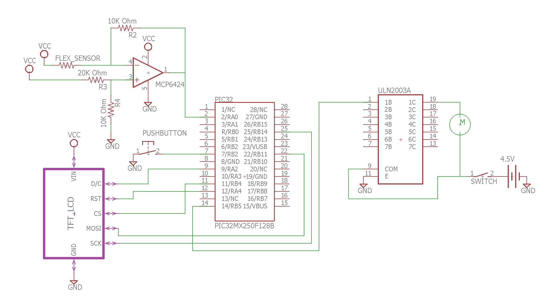
Appendix E Figure 7 shows the entire circuit diagram of our device.
Biological Research and Mechanical Placement of Sensor
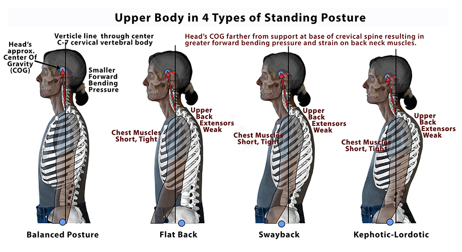
While completing this project, biological research was done on the different types of bad postures in order to get a better sense of where our sensor should be placed. There are three types of faulty posture: flat back, sway back, and kephotic lordotic.3 These are summarized in Figure 8:
Figure 8: Three types of poor posture, as related to the upper back3
What all three of these positions have in common is that due to the fact that the head’s center of gravity is more forward in comparison to the base of the neck, the neck bends and the shoulder blades hunch forward. As a result, the back extensors of the neck get overworked (to prevent the head from tilting too far forward), while the front extensors get underworked; which can cause chronic neck pain. Furthermore, the hunching of the shoulders can cause weakening of upper/mid back extensors, tightening in the front chest muscles, and the weakening of the muscles that keep the shoulder blades near the spinal column due to the widening of the blades, to name a few.
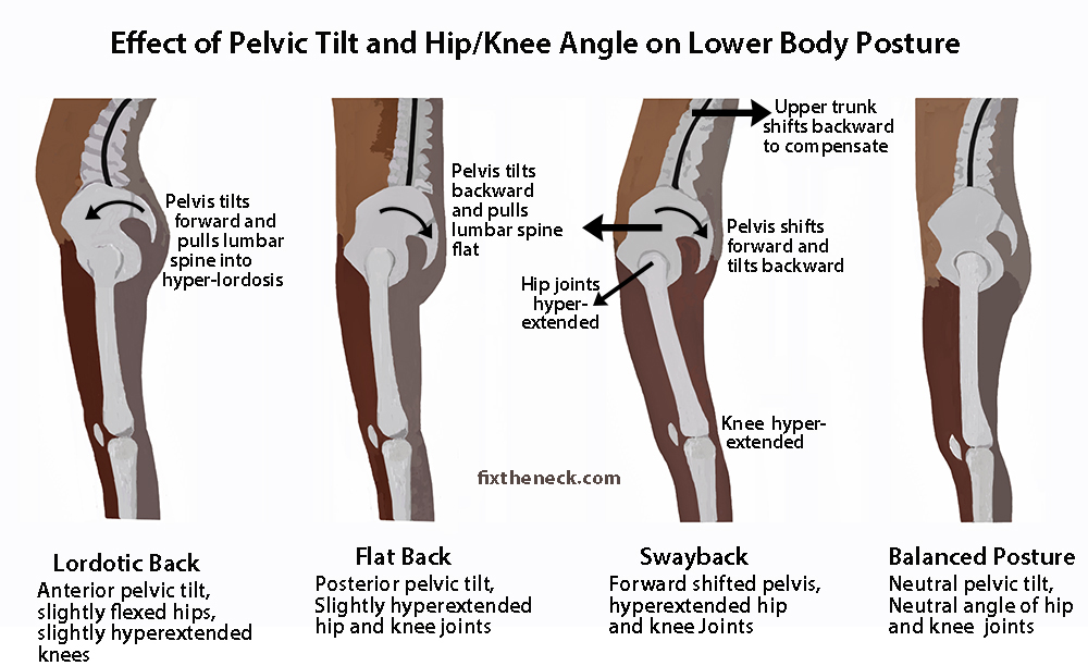
Having good lower back posture actually helps keep good upper body posture because the inward curve of the lower back (called the lordotic curve) is what positions the upper body above the hips.3 The degree of tilt in the pelvis is what determines the degree of curvature in the lordotic curve, and this tilt is dependent on four muscles: the abdominals, the hip flexors, the hip extensors, and the lower back extensors. Neck posture is also determinant on the lower back, as the angle of hip and knee joints helps shape the neck. Figure 9, below, depicts the effects of poor lower back posture for the same three bad postures mentioned above:
Figure 9: Three types of poor posture, as related to the lower back3
Given the results of our research above, we tried experimenting with flex sensor sensitivity in three main locations: a) the neck, b) the upper back (we tried both on the shoulder blades and in between them), and c) the lower back/in the lordotic curve. We also experimented with using different flex sensor sizes. Regarding the latter, we found that the 2.2” flex sensors that we had were not able to measure a large range of body motion, so we decided to experiment more with the larger 4.5” flex sensors throughout our project. After adding sensitivity circuits to help widen the range between min and max read values (see hardware), we began by experimenting with the lower back. By placing the sensor in the lordotic curve, we were able to get a wide range of values between poor and good posture, and we believe this is due to the larger range of muscular motion that the pelvic tilt provides. Also, the shape of the lordotic curve made stretching and bending the flex sensor more ideal, even when the sensors were placed on the felt and foam piece made for the sensor.
Next, we tried experimenting with the upper back. We originally wanted to place one smaller flex sensor on each shoulder blade; however, we found that, unlike the lordotic curve, the smoother plane of a shoulder blade is not as ideal for bending and straightening the flex sensor. We then hypothesized that putting the sensor in between the shoulder blades would potentially have a larger range of read values, as the movement of the shoulder blades towards the spine could cause the sensor to bend at both ends. However, we believe that even the 4.5” sensor was too small for this configuration, as we were not able to get a wide enough range of numbers to accurately sense the difference between good and bad posture.
Finally, we experimented with using a sensor to measure the movement of the neck, but we were unable to get a satisfactory reading; this could be due to the fact that the neck is not as curved as the lower back or because our sensor configuration was not ideal for the neck. Based on our own experimentation and the information we obtained from our research, we confirmed that lower back posture heavily influences the posture of both the upper back and neck, so we decided that a 4.5” sensor on the lower back was sufficient in aiding a user to maintain good posture.
Software Design
Overview
The code can be separated into two portions; the user interface and interaction between hardware components.
TFT Display Screen
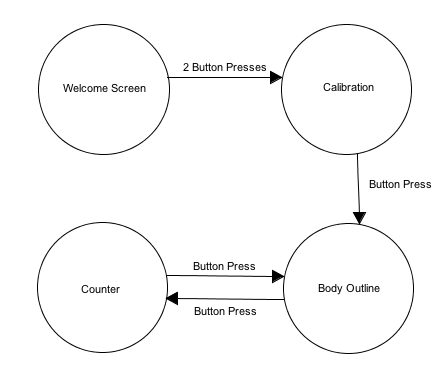
A diagram detailing the display order on the LCD is shown and explained below in the following subsections.
Figure 10: User Interface
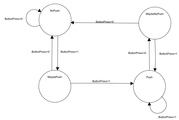
In order to toggle the screens, a state machine, shown in Figure 11, was used to debounce the button.
Figure 11: State Machine to Debounce
The system initially starts at the NoPush state, where no push is detected. This could apply when the system is first reset to the home screen or if the system is at any screen without an immediate subsequent push. If there may have been a push of the button, the state then transitions to the MaybePush state, where it is determined whether the button has indeed been pressed or if it was a false press. If the button has not actually been pressed, the state transitions back to the NoPush state, otherwise, the system transitions to the Push state, where the user will be greeted with a new screen (depending on what the current and next screens are). Once the system has transitioned to the Push state, the system will stay there until there is a detection of the release of the button. From this, the state then transitions to the MaybeNoPush state, where the system returns to the Push state (if it is determined that the button is being held down) or NoPush state (if the button has been released).
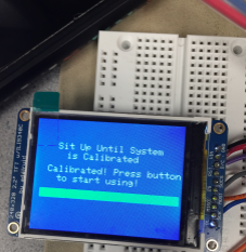
The user is first greeted with a welcome screen, shown in Figure 12, with a welcome message, our slogan and instructions for the user.
Figure 12: Welcome Screen
From the home screen, two button pushes takes the user to the calibration screen shown in Figure 13. During calibration, as the user maintains good posture, the system captures the readings of the flex sensor and uses this value as the threshold for good posture. In order for the system to be calibrated, the user must stay still in his or her good posture stance, as a loading bar fills across the screen. To determine the end of calibration, three successive readings from the flex sensor are stored, and if these values are within a certain percent of each other, then the system has finished calibrating. Otherwise, the system will continue checking the readings from the flex sensor and wait until there are three successive values that meet this requirement. Once the device is calibrated, the screen prompts the user to press the button to begin using the device.
Figure 13: End of Calibration State
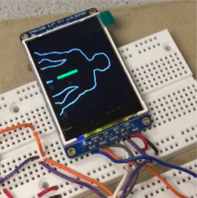
Once the system is calibrated, the user can press the button to advance to a screen that displays a body outline. The body outline is a white silhouette image of a male back. The image was found online and converted into header file with the assistance of a few lines of Bruce Land’s Matlab code, found in Appendix E. All of the white points being converted into x and y coordinates, and these numbers were then stored into a header file named “bodyoutline.h”. Additionally, a green bar is drawn on the screen to provide a visual indication of the location of the flex sensor and the vibration motor. This bar will turn red during periods of poor posture as determined by the calibrated threshold value. This body outline screen is shown in Figure 14.
Figure 14: Body outline screen with green rectangle indicating that the user is in good posture
Pressing the button once more bring the user to the counter screen. The purpose of the counter screen is to track the number of instances of poor posture a user might have and provides a quantifiable value that the user can note visually. Each time a user has poor posture based on the flex sensor’s reading, the tracker value increments by one. An image of the counter screen is shown in Figure 15.
Figure 15:Tracker for poor posture instances
Pushing the button repeatedly after this will toggle between the body outline screen and the counter screen; this serves a familiar concept currently implemented by devices such as FitBit.
Flex Sensor Protothread
The project uses only one protothread which is used to constantly check the values being read from the flex sensor. By constantly reading the flex sensor values, there is a more accurate calculation of the poor posture state. To determine when this is reached, a conditional statement is used, and if there is an instance of poor posture, which is based on a percentage decrease in the flex sensor reading, the bar on the body outline screen changes color from green to red. On the counter screen, the counter value is incremented by one. Finally, the vibration motor turns on, providing a physical indicator that the user is in a poor posture state.
Results
Our final design deviated slightly from our initial idea, however, we still accomplished our goal; to create a wearable device that determines correct posture and indicates if a user is in bad posture. We used only one flex sensor on the lower back to determine poor posture instead of five placed in multiple areas on the back. Only one vibration motor was used to signal poor posture and this signal was strong enough for the user to notice. In addition to these hardware modifications, we also added a calibration setting as well as multiple screens for the user to view.
We made calibration intuitive for the user. First, the user gets into their good posture and then presses the button twice to navigate from the welcome screen. The calibration takes about two seconds to complete. We made this quick so the user does not have to stay still for a long period of time. To show how much time is left for calibration, we also included a loading bar. There is a message at the end of calibration to indicate that the posture monitor is ready to use and adjusted specifically for the user.
The flex sensor thresholds are set based on a certain percentage that the user deviates from his or her good posture, and we tested this accuracy by displaying the outputted values from the flex sensor and ensuring that the motor turned on or off appropriately. The PIC32 is constantly reading values from the flex sensor, giving an accurate measurement of the user’s posture, and the response time of the vibration motor is almost immediate. Once the PIC32 receives a value past the threshold for good posture, it turns the vibration motor on until it gets a value that is back in the good posture range. This quick response is necessary to alert the user right away that he or she is in poor posture allowing him or her to correct him or herself.
Our LCD screens do not show any flickering and toggling between them is simple. We debounced our pushbutton in order to ensure smooth transitions from the body outline screen to the screen that keeps track of ‘back breakers’. We made sure to add an instruction on the welcome screen so the user knows how to begin, and our calibration screen also provides instructions for the user as well. The body outline screen gives the user a visual cue along with the vibration motor which we included so users who have nerve damage on their back or for those who cannot feel the vibration motor due to other reasons can still use our device. Our calibration mode makes our device unique to each person because everyone’s good posture is different, yet our device can work on anyone. Lastly, the screen that keeps track of ‘back breakers’ tallies how many times the user experienced poor posture. We hope that this feature allows the user to observe how many times he or she slouches and will encourage them to decrease the number of ‘back breakers’.
Unfortunately, our device is not adjustable due to the size of the compression shirt we used. As of now, the shirt is a women’s medium. This limits who can use the device, but this could be solved by attaching the device to a different sized compression shirt or an adjustable vest that is snug enough to the user’s body to obtain accurate readings. Our device is simple to use for people of most ages. For those who cannot see, we have the vibration motor to indicate poor posture and for those who cannot hear, we have the vibration motor as well as a visual display to indicate poor posture.
We did not experience any interference from other projects that affected our results because nothing in our circuit was wireless. Although interference from other projects was not a concern, we did have some trouble with loose connections on our breadboard. This can be solved by soldering the connections or creating a printed circuit board for a cleaner design.
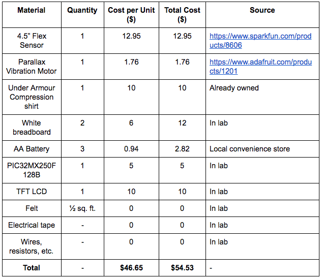
Safety was a concern as we worked on our project because this device was going to be placed on the user’s body. Before testing the components on the user, we first connected and tested the components in the lab space. Our main concern for safety was the vibration motors because we noticed that these motors tended to get hot the longer they stayed on. We found that including the driver and external power source helped solve this issue. All of the other components and circuitry were not placed on the user, but we still made sure that the connections were as secure as possible and that nothing was short-circuited or connected in a way that would harm the user. We also heat shrunk the wires we soldered together to prevent the components from falling apart as well as protecting the user from accidentally touching the exposed wires. We tested the device on ourselves multiple times before concluding that our device was safe for others to use. Our final parts cost list can be found in Appendix C.
Conclusion
In terms of functionality, our design (in terms of placement of the sensor on the shirt, software on the TFT, etc.) worked exactly as expected. This means that when a visually poor posture was reached, our software (i.e. body image screen + “back breaker” counter) and hardware (vibration motor) would indicate the change correctly. This was true for going from both good to poor posture and vice versa. If given more time to work on this project or if we had the opportunity to do this project again, we would have spent more time on the setup of the flex sensors in order to make them look a bit more sophisticated (i.e. not use flex and foam) and would have found another way to get the flex sensor to bend in the same fashion. Also, we probably would have tried creating a wireless or bluetooth system, where the flex sensors could communicate with the PIC (and, consequently the TFT) without using so many wires. Along with is, we could have thought about doing one of two things: use a mobile app to help control the device and collect user data or use the TFT to create a wearable device such as a user watch setup (similar to a Fitbit or Apple Watch configuration). Another thing that could have been done is designing a system where the flex sensors were hidden from view (i.e. design a more aesthetically pleasing shirt).
The shirt used for our final design complied with ISO 10993-10:2010: Tests for irritation and skin sensitization and ISO 13732-1:2006: Hot Surfaces and Standard ECMA-287, as the material of the shirt acted as a layer between skin on the back and the flex sensor. Also, the use of felt and foam provided an extra layer that prevented irritation and/or hotness on the skin from the flex sensor. The single vibration motor used in our system also complies to ISO/TC 108/SC 4: Human exposure to mechanical vibration and shock because an adequate amount of power was supplied so that the vibration motor could successfully notify the user of poor posture but was not too much to injure him/her, the motor did not produce shocks that harmed the user, and the Dri Fit shirt again provided a layer of protection between the vibration motor and the user’s skin (decreasing the chances of irritability, etc.).
Matlab code used to create a header file for an image (for our body image screen on the TFT) was written by Bruce Land and was borrowed with his consent for the purposes of this project. All other code was original code either written for a previous 4760 lab submission by this group or new code written for this project. There were no patent issues or non-disclosure agreements that needed to be dealt with for this project, for both individual parts and for the overall design. We believe that our project has the potential to be published, as medical devices have been a very popular topic in the past few years. We think that, with a few optimizations, we would be able to brand the product; in terms of patents, we could potentially patent the way the flex sensors were used to measure posture, although we will need to look into specifics in the future to make sure that this is possible.
The choice of materials we used as well as the decision avoid direct contact with human skin was done with number one of the IEEE Code of Ethics in mind. As data was not sent wirelessly or put into a public database, we feel that we complied to both number 1 and number 2 of the code. All claims about the functionality of this project (number 3) were done after quantitative calculations about the accuracy of the device, and there was no sort of bribery done that changed the design/functionality of this project. Numbers 5 and 6 were completed by doing biological research about posture beforehand and consulting with Professor Land and our TAs to make sure that we understood all pros and cons of our design choices. As we are a very diverse group of individuals at a very diversity-conscious university, number 8 was not difficult to uphold. Working on the placement of our sensors and the layout of our device supported the recognition of number 9, as it is especially important with wearable technology to not bring harm to a user. Lastly and most importantly, our team upheld number 10 by having open communication with each other and asking each other questions when necessary so that we could learn from one another.
No legal considerations were needed for our final design. In the future, if we decide to pursue the creation of a phone app or optimize our design by using a wireless system, the legal issue of patient data privacy and protection will need to be addressed.
Appendix A
The group approves this report for inclusion on the course website.
The group approves the video for inclusion on the course youtube channel.