"One-voice music sequencer with Frequency Modulation synthesis, Karplus-Strong Synthesis and wavetable."
-project soundbyte
This project stems from our passion for music and the desire to build a device that can inspire creative works from individuals regardless of their musical backgrounds. We designed a music sequencer using the PIC32 MCU with a keypad-TFT display user interface and external DAC sound output. This music sequencer helps users generate music patterns based on the sounds they selected and allows users to save and playback the generated music pattern. Individual sounds are produced using either FM synthesis (with snare drum generated using wave table) or Karplus-Strong Synthesis depending on the mode the user is in, and aim to mimic sounds ranging from percussion instruments to string instrument such as guitar.
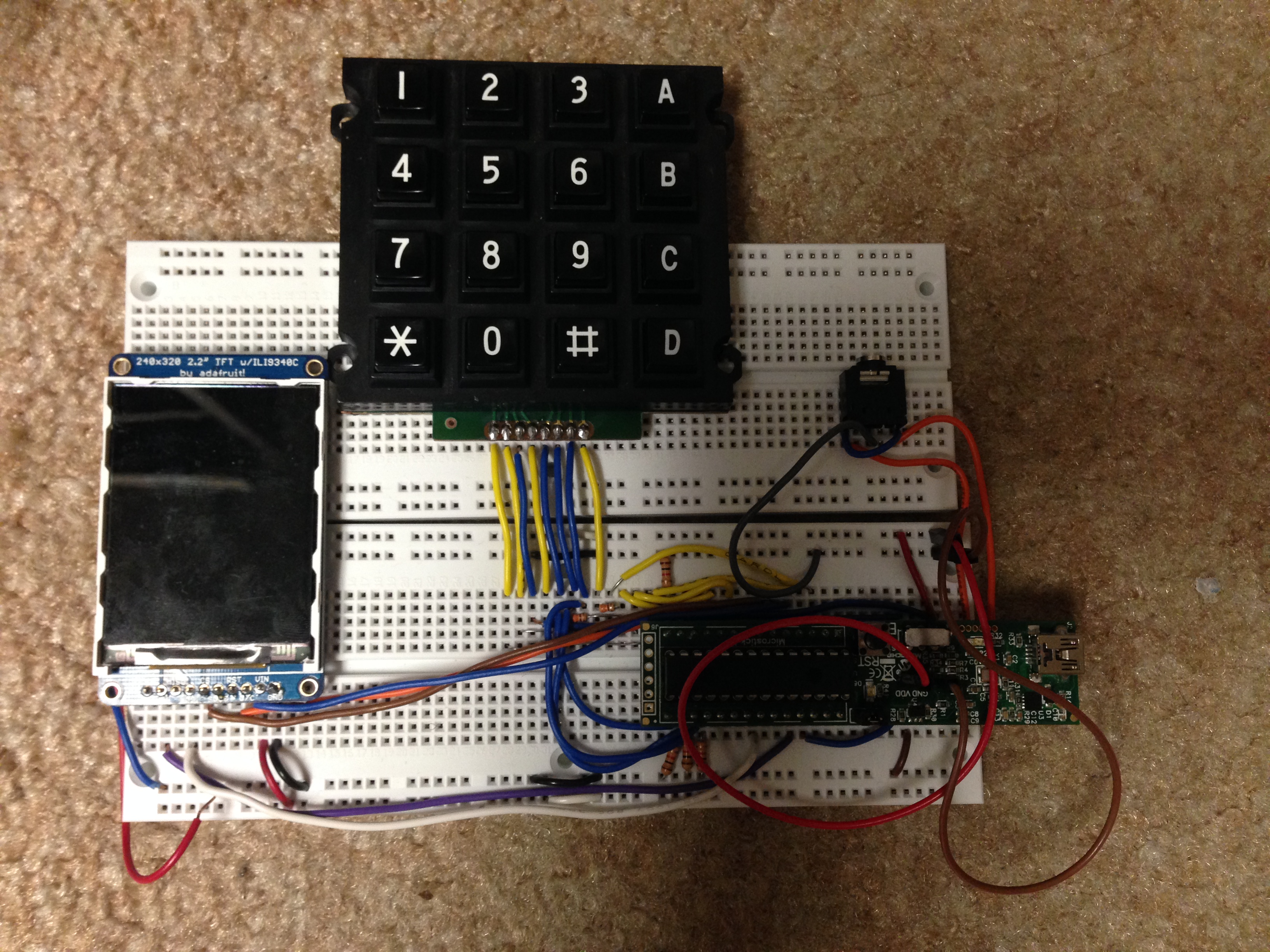
The finished product
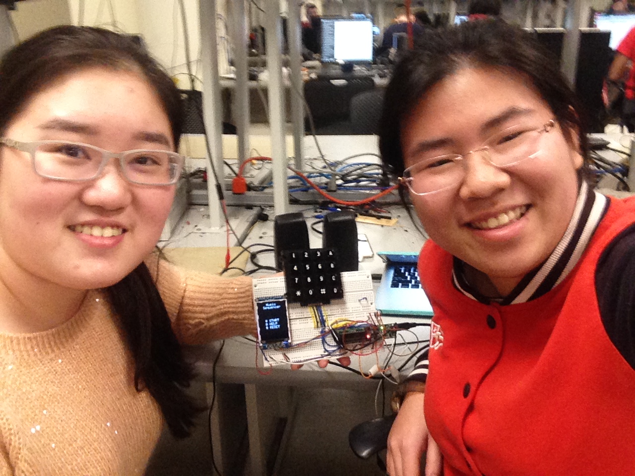
The designers
High Level Design top
Rationale and Sources of your project idea
There are different ways to synthesis sounds and some are more suitable for producing sounds of certain timbres. For our project, we decided to use a combination of Frequency Modulation (FM) Synthesis and wavetable for generating sounds that more closely resemble percussion instruments such as the bass drum and the triangle and other sound effects such as bounce ball. We also used Karplus-Strong Synthesis to generate 9 string-like sounds that range from C4 to D5 and more closely resemble string instruments such as the guitar. Lastly, we used wave table to particularly generate the snare drum.
The main motivation behind this project is our passion for music, the curiosity to learn more about how sound and music are synthesized and the desire to help everyone discover the musician in them. Through working on this project, we leveraged on what we have learnt in class while simultaneously exploring new sound synthesis methods. For hardware, we mostly expanded on what we did in Lab 2. We soldered headers to the keypad and modified our keypad debounce finite state machine (FSM) to work on a 16-button keypad. We also remapped some of the microcontroller unit (MCU) pin connections so we could fit the thin-film-transistor (TFT) display, an external digital-analog-converter (DAC) and the keypad using knowledge accumulated from all previous labs. For software, we implemented FM Synthesis by learning from Professor Bruce Land’s example code and understanding the mathematics behind it. We also studied Karplus-Strong by reading the original published result by Karplus and Strong. Lastly, particularly for snare drum, we used a wave table to generate a sound that more closely resembled a snare drum and we made use for what we learnt from Lab 2 to accomplish this.
Overall, we were able to complete this project successfully by consolidating what we have learnt from previous labs and doing additional researching and reading for the different synthesis method.
Background math
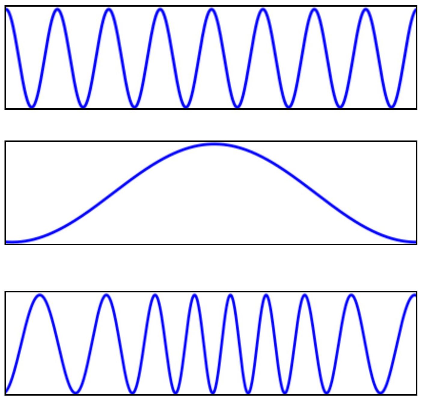
Figure 1. FM Synthesis (top: Carrier; middle:modulator; buttom:result)
As we can see from the diagrams, in order to synthesize sound for a particular instrument, we will need two curves -- one acts as the carrier frequency and the other acts as the modulator. By performing operations on these two waves and setting different parameters as we will explain in detail below, we can synthesize the different sounds used in our project.
The basic waveform for FM Synthesis is described by the following equation and we can break this equation down into different parts to be computed separately before putting these together to obtain the wave equation:

Firstly, the envelope used in the equation can be generically described by the following equation:

Specifically for the fm and main envelope, the equations are as follow:


Computing the exact wave equation would require infinite values since t can be infinitesimally small and the way to resolve such problems is always using sampling. Hence, the wave equation wave_main we actually computed in our code is as follows:

For now, just note that this is the way to compute the outermost sine function. We will look at why this works as well as what are the terms needed to compute phase_accum_main >> 24 in the Software Section.
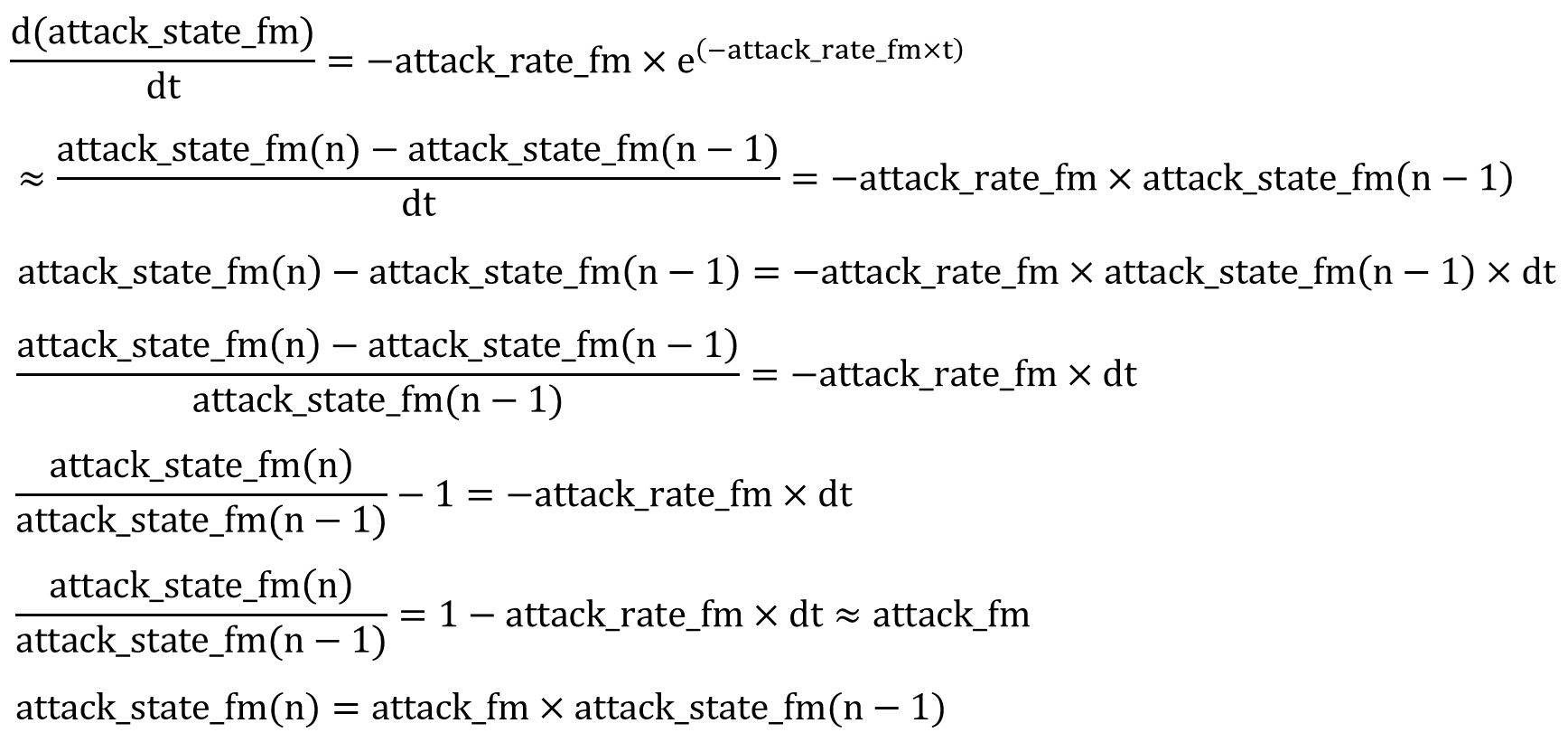
Next, we observe there are two exponential terms in each envelope equation which we will denote using the variables dk_state_main, attack_state_main, dk_state_fm and attack_state_fm respectively.


We applied first order differential equations to compute the exponential terms. The equation can be described as follow:
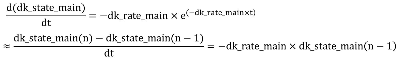
Rearranging the equation, we get the following form:
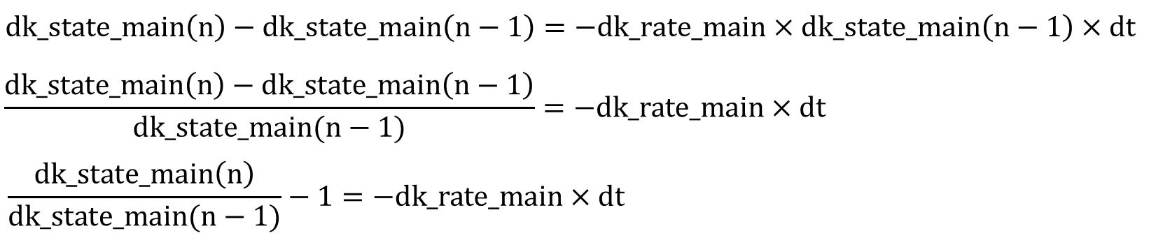
Applying Euler approximation with 0≤dk_fm< 1 and dk_rate_fm*dt < 1 for Euler approximation), we can obtain the following equation:
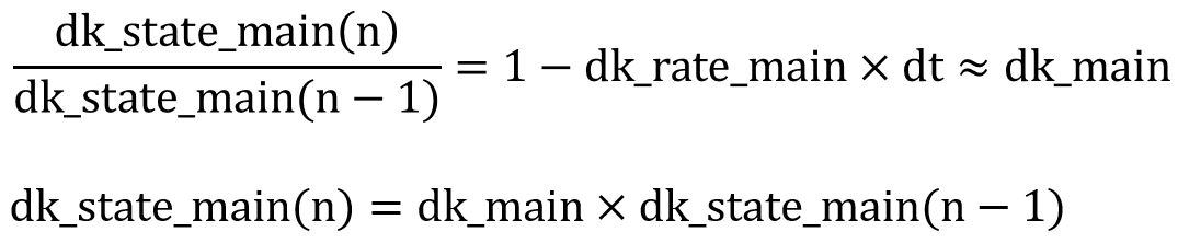
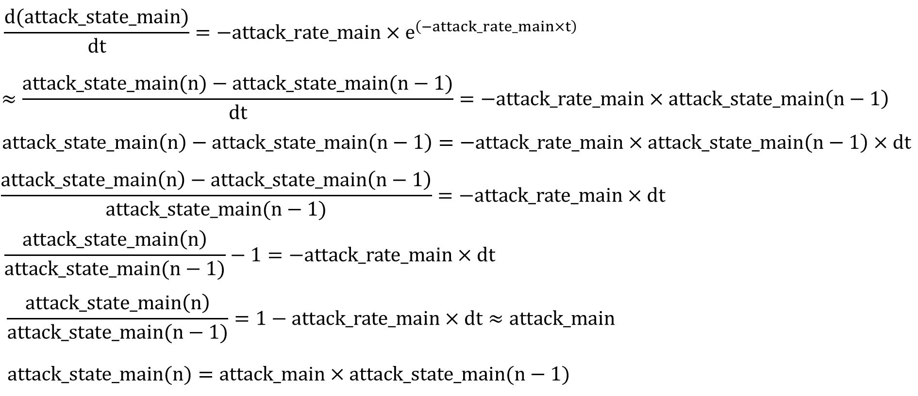
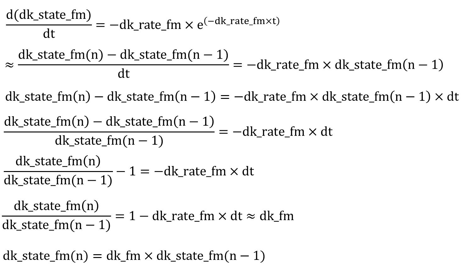
Rearranging the terms once more, we note that we can compute the term dk_state_fm(n) by multiplying the previous dk_state_fm term i.e. dk_state_fm(n-1) with a constant denoted as dk_fm in our code. Applying the similar logic, we can compute the equation for variables: attack_state_main, dk_state_fm and attack_state_fm. The specific equations are shown below:
attack_state_main
dk_state_fm
attack_state_fm
The details on what the time step between dk_state_fm computations is and the implementation of this algorithm will be further explained in the Software Section.
Hardware top
program details. Could someone else build this based on what you have written? hardware details. Could someone else build this based on what you have written? Be sure to specifically reference any design or code you used from someone else. Things you tried which did not work
Hardware Design
There is not much hardware design as we were able to leverage on our knowledge from Lab 2 to set up the hardware with some modifications to accommodate the additional 4 keys associated with the 4x4 keypad. As such, we had more time to learn and experiment with the software side of the project which deals with the sound synthesis. The mapping between our MCU, TFT, keypad and external DAC can be seen from the schematics in the Appendix. We encoded the keys so that we can detect which keys are pressed on the keypad but expanded the encoding for the 4x4 keypad. We looked up the datasheet for the Jameco 169244 16 buttons keypad as shown in Appendix.
Software top
Software Overview
The objective of the project is to create a dual-mode one-voice music sequencer that can synthesize both acoustic and electric sounds and produce music composed with a random combination of a stream of keypad inputs from the user. Using frequency-modulation, we were able to synthesize 8 different sound effects such as bass drum, triangle, cowbell, temple bell, wood block, struck metal, hi-hat cymbal and bounce-ball sound. Using Karplus-strong synthesis, we were able to model string plucks and synthesize the sound of guitar. Finally, we were also able to produce crashing snare drum using a wavetable generated by a matlab script, which processes a WAV file and truncate the PCM values to 4-bits to store inside a header file. Combining all three techniques, we successfully synthesized 18 different sounds and play them back based on user inputs.
Software Design
Keypad Finite State Machine (FSM)
On start up, our TFT will be displaying the home page. At the home page, the user can choose to start experimenting with the different sounds straight away, enter help section to read about how to use the device or reset the device by clearing out the stored sequence.
When the user presses * to indicate start, we will set a start flag to indicate start. Once the start flag is set, we will no longer listen for the * key and will instead check for keys 0-9, A-D. When the user presses 0 too indicate help, the help page will be loaded and the help flag will be set to 1. In the help page, we only listen for keys *, 0 and # for indicate previous, exit and next page since we have two pages for help. This is achieved by only checking if the key pressed correspond to one of these buttons and do nothing otherwise.
Once the user presses * to start, by default, the device is in the percussion/sound effects mode. The user can press buttons 0-9 and as each button is pressed, the respective sound will be produced. Apart from the snare which is done by the wave table, other sounds are generated by FM Synthesis in the ISR. The parameters for the FM Synthesis is set based on which key the user pressed. Once the user has determined which instruments he/she wants to include inside the generated sequence, the user can press A to enter the record mode. When the user presses A, a recordMode flag will be set to 1. In the recordMode, we will remember the keys the user pressed so the random playback sequence can be generated. To finish entering the instrument and end the recordMode, the user will press A again and once detected. We will set the recordMode flag back to 0. At this point, the user can choose to listen the randomly generated playback sequence by pressing the B button for playback.
If the user wants to enter the acoustic mode, the user must select this mode first before doing anything else after pressing * to start. This mode is entered by pressing the D button. In this mode, we enable recordMode straight away and the user chooses which sounds he/she wants to use. To stop the recordMode, the user presses D again. To enter the playback mode from the acoustic mode, the user needs to press C. Once again a random sequence is generated based on the user input keys.
Frequency-Modulation Synthesis
Generating and indexing into sine table for FM Synthesis
For FM Synthesis, the first step is to generate a 256 entry sine table, sine_table. The period of a sine table is 2π i.e. approximately 6.284. Since we want to get 256 entries, this means we increment each sample by 6.283/sine_table_size. By indexing into the sine table from 0 to 255 periodically and sequentially, we can indeed compute a sine function.
Computing sine function using sin(phase_accum_fm >> 24)
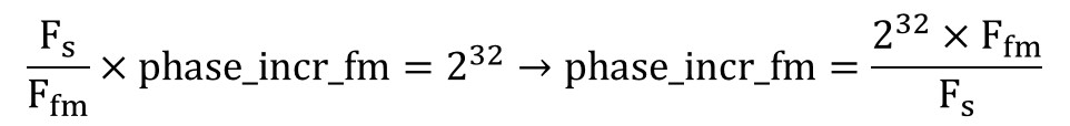
Recall from the section above, we mentioned we could generate the outermost sine function by using the equation sin(phase_accum_main >> 24). Let’s first look at the original wave equation named wave in the Background math section and start to unwrap the equation from the innermost sine function and arrive at the expression for phase_accum_main . We can regard the sin() function as a sine table and the terms inside the brackets of () as the index into the sine table. To index into 256 entry sine table, we need an 8-bit number. This can be achieved by using a phase accumulator phase_accum_fm and taking its most significant 8 bits i.e. sin (phase_accum_fm >> 24). phase_accum_fm is incremented by a fixed amount, phase_incr_fm, every time the ISR is triggered as shown by the equation below:

This means if we are looking at the most significant 8 bits of phase_accum_fm, they will go from 00000000 to 11111111 and will allow us to sequentially index into the sine table. This phase_incr_fm is a 32bit number and is different based on the instrument and the frequency of the sound produced by the instrument. Our ISR is triggered every 2K timer counts. Our clock is running at 40MHz i.e. 40M timer counts per second, this means 2K timer counts is equal to 2K/40M = 2000/40000000 = 0.00005 seconds and the frequency at which our ISR is triggered is 1/0.00005 = 20KHz. Since our ISR is triggered 20K times every second, the phase_accum_fm will be incremented by 20K*phase_incr_fm every second. Since every ISR we index into the sine_table, this also means we are sampling the sine_table at a sampling rate of Fs = 20KHz or a period of 1/Fs = 0.00005. Furthermore, since we are constantly adding phase_incr_fm to phase_accum_fm, we know phase_accum_fm will eventually overflow. Since every ISR phase_accum_fm is incremented by phase_incr_fm and if we let n be the ISRs it takes for the 32-bit number to overflow. n*phase_incr_fm = 2^32.
Furthermore, since we know the time per ISR is 1/Fs, the time for n ISR is n/Fs. When overflow occurs, this means we have finished indexing one round of the sine table which corresponds to the period of the sine wave we generated. In other words, n/Fs is the period of the sine function and Fs/n will be our frequency Ffm.
Substituting the above equation into the previous equation, we get the following relationship:
Next, from the original equation, we see this inner sine function is multiplied by the envelope_fm which is mentioned in the Background Math subsection. There are different parameter associated with the envelope and we vary these terms to produce different instrument and sound effects. When the dk_fm and dk_main terms are greater, this means dk_rate_fm and dk_rate_main are smaller. Hence, the decay rate will be slower. Similarly for attack, when the attack_fm and attack_main terms are smaller, this means attack_rate_fm and attack_rate_main are greater. Hence, the attack rate will be faster. Just as how Ffm*t is converted to phase_accum_fm+phase_incr_fm, we can similarly convert Fmain*t to phase_accum_main+phase_incr_main. However, there is still an additional term inside the outer sine function, which is the multiplication of the inner sin function and envelope_fm both calculated above. The relationship between phase_incr_main and Fmain is phase_incr_main = (Fmain * 2^32)/Fs.
Thus, combining everything together, we can see phase_accum_main can be computed as follows:

Lastly, we come full circle as we use this term >> 24 to index into the outer sin function, and multiply by the env_main to compute the wave_main.
Karplus-Strong Synthesis
Because Karplus-Strong Theorem is simple and effective when modeling string-like sounds, when implementing the second mode of the synthesizer that outputs sound of a guitar, we chose to use Karplus-Strong Synthesis. To model string-like sound, the fundemental logic behind Karplus-Strong is a physical model of the plucking process of a string. Before a string is plunked, it contains zero kinetic energy. However, as soon as it's plucked, the string will start vibration with immediate damping due to the loss of energy in friction. Karplus-Strong theorem suggests that at the moment that a string starts to vibrate, its kinetic energy is at its max value, which would result in sound with complex harmonics. Then, just as the picture below shows, the decrement in kinetic energy would result in fewer harmonics in the sound and eventually the sound stops when the string stops vibrating.
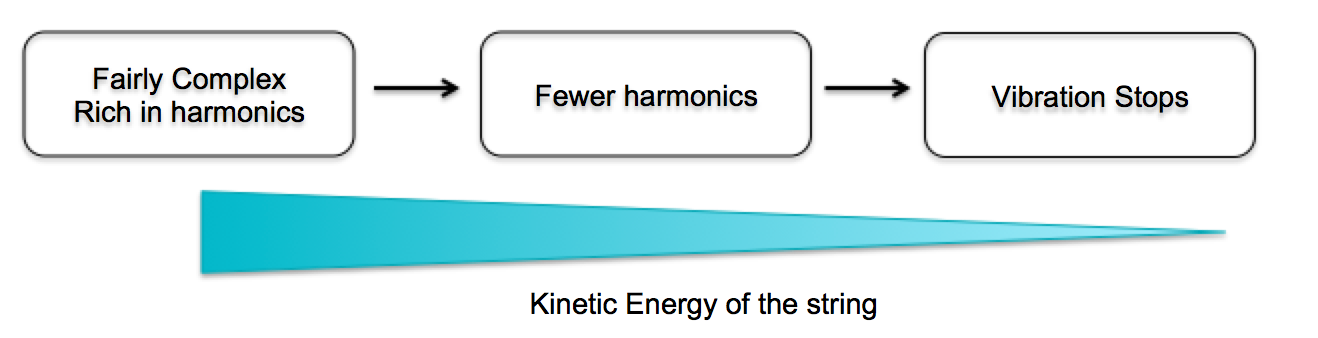
Figure 2. KS Physics Model
With the above physical model, the algorithm shows that when synthesizing a string-like sound, the array for every new node should start with random values, which represent the complex harmonics at the beginning stage of the vibration. More specifically, a random wavetable has essentially equal harmonics up to the Nyquist frequency. Then, to model the lost of harmonics, the algorithm applies a simple averaging scheme to simulate a low-pass filter that removes high-frequency harmonics. In the design we chose, the frequency of the node is determined by the sampling frequency and the length of the array that's allocated and initialized to a random table. The reason is that the program will read and update the array over and over again, which creates a sound wave with a frequency of (Fs/array_length). Then, when read each sample from the array, we fetch both the current sample and the previous sample we have seen and compute either the positive average or the negative average of the two samples with equal probability. Finally, the computed result would be store back to the current entry of the array that we read. The averaging operation simulates a low-pass filter because by averaging the consecutive samples, we effectively reduces the rate that sample values change. With a slower changing rate, harmonics at high-frequencies will be eliminated while the lower-frequency harmonics remain. A sample result of this simple yet effective scheme is shown in the picture below. Note that the random waveform at cycle 0 gradually gets flatter and approach a straight line as time passes.
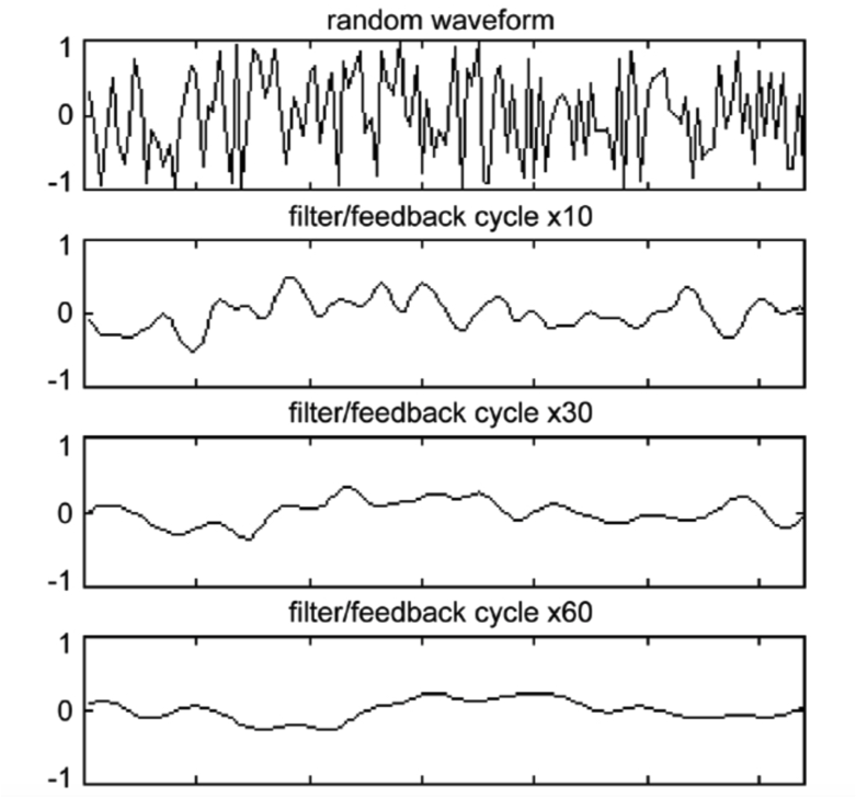
Figure 3. Filter and Feedback loop
Implementation: To implement Karplus-Strong synthesis for sounds of different frequencies, we included dedicated arraies for each sound to produce. However, to save memory, we make all of them share the same random array. In the setup of the program, we filled all the arraies with random values from the random array. When user starts to press keypad keys, a flag would be set and a sequence of array reads and updates would be executed when the ISR fires. In the ISR, the current value of one target array is read out and a updated value would be calculated and write back to the array. The sound will keep playing until 4000 ISRs have been executed and the target array would be reset to random values at that time. Note that the main control of the logic is the keypad FSM described above. The key pressed is used to choose which data array to read out.
Playback Sequence Generation
After the keypad can successfully take in user input and the synthesizing logic performs correctly. We extended the project to allow user to playback an extended music sequence formed by the stream of keys/sounds they choose. Again, like all other functionalities, playback is designed as a mode of the device. When the sequence stops, the user can feel free to listen to the sequence again. The current length of the sequence was set to be 50, which is an optimal length, we believe, to enjoy the composition without getting bored of it. Note that the sequence is not wasting any additional memory, but is generated on the fly when user clicks playback key. We buffer previous key entries from the user and extend such simple pattern to more complex and interesting sequence. This functionality was meant to give the user more fun and also stimulate their interest in composition.
Results top
TFT Start Page
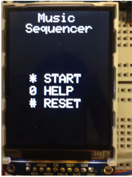
Figure 4. TFT start page
Wave Table result:
| Output | key |
|---|---|
| Snare | 1 |
FM Synthesizer Result:
Using the parameters in the following table and the FM equations shown in the high-level design section, we generated sounds that resembles percussion instruments and fun sound effects for users to play with. The sample sound outputs are also linked in the first column.
| Output | Key | F_main | F_fm | Attack_main | Attack_fm | DK_main | DK_fm | depth_fm |
|---|---|---|---|---|---|---|---|---|
2 |
100.0 |
100.0 |
0.0 |
0.0 |
0.87 |
0.88 |
4.0 |
|
3 |
50.0 |
90.0 |
0.0 |
0.0 |
0.97 |
0.98 |
1.0 |
|
4 |
2000.0 |
3000.0 |
0.0 |
0.0 |
0.97 |
0.98 |
2.5 |
|
5 |
800.0 |
1400.0 |
0.0 |
0.0 |
0.97 |
0.98 |
2.5 |
|
6 |
213.0 |
713.0 |
0.0 |
0.0 |
0.5 |
0.88 |
5.0 |
|
7 |
123.0 |
234.0 |
0.0 |
0.0 |
0.99 |
0.97 |
2.5 |
|
8 |
123.0 |
234.0 |
0.0 |
0.0 |
0.87 |
0.88 |
4.0 |
|
9 |
231.0 |
734.0 |
0.0 |
0.0 |
0.98 |
0.99 |
2.5 |
As stated in the background math section, the sound is produced using exponential attack and decay schemes, which would generate an envelope over the sinusoidal signal. To view the shape of such an envelope, we also captured pictures of the resulting signals:
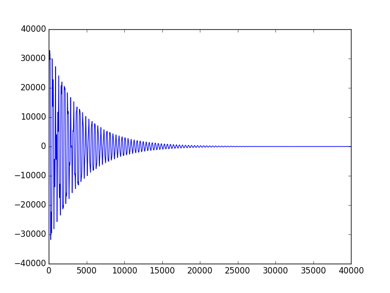
Figure 5. Bass Drum Signal
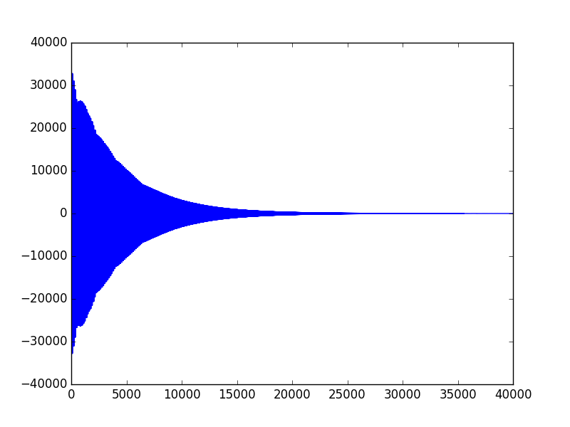
Figure 6. Triangle Signal
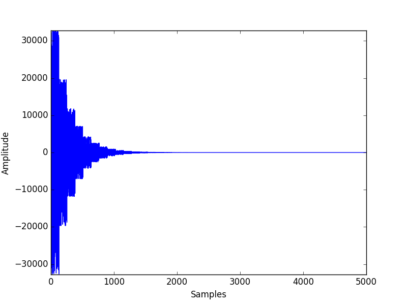
Figure 7. Hi-Hat Cymbal Signal
Observation: First, all three graphs show exponential decay after a burst of amplitude at the beginning of the sound. The Bass Drum signal and Triangle signal both have the same decay rate, which can be observed from the identical shape of the overall envelope. However, from the table above, we can see that Triangle signal has much higher frequency than the Bass Drum signal, which is also indicated in the graph above as the Triangle wave is much denser than the Bass Drum one. Note that, the density of the sinusoids under the envelope is directly proportional to the frequency of the signal in FM synthesis.
Second, comparing the shape of the Bass Drum signal to that of the Hi-Hat Cymbal signal, we can clearly observe a shorter and faster decay on the Hi-Hat signal, which produces the "crushing" sound effect that's needed to synthesize authentic cymbal sound. The faster decay is achieved by smaller dk_main and dk_fm values, which would result in a larger decay factor according to the analysis in the High-Level design section. With a larger decay rate, the decay phase of the signal would be sharper, which is exactly the observation here.
Karplus-Strong Synthesizer Result:
The following table captures the acoustic guitar-like sound that we were able to produce using Karplus-Strong Theorem. The array length field is the length of the dedicated array we initialized in the program for that node. As explained before, the frequency of output signals and the array length are closely related and such correlation can be observed below. The sample output data files are generated by an additional python script that we wrote.
| Output | Key | Frequency | Array Length |
|---|---|---|---|
1 |
261.626 |
76 |
|
2 |
293.665 |
68 |
|
3 |
329.628 |
60 |
|
4 |
439.228 |
57 |
|
5 |
391.995 |
51 |
|
6 |
440 |
45 |
|
7 |
493.883 |
40 |
|
8 |
523.25 |
38 |
|
9 |
587.33 |
34 |
Overall: The program has no notiable delay and the sounds generated have no notiable clipping effect (even though the python program does generate the Karplus-Strong sound with little clipping). In the video linked below, we demoed both FM and KS sequences. Overall, we believe that we have achieved the goal of the project and we are proud of our product.
DEMO VIDEO
Conclusions top
The sound synthesis that we were able to accomplish is beyond our expectations, since our initial proposal only contains percussion-like sound production and we eventually accomplished a two-mode device. However, if we have more time, we would love to extend the controlling feature of the keypad and also consider better algorithm to compose sequences of playback music. Some of our proposed improvements are as follow:
1. Instead of generating music sequences randomly, we can apply some music knowledge to determine which type of sounds will sound better together.
2. Currently our two modes can be accessed separately, we would love to combine these two modes so we can play percussion instruments, sound effects and the guitar sounds all together and give the user a wider range of composition freedom.
3. We would love to incorporate tempo change through the use of a potentiometer. By adjusting the potentiometer, the music sequence can be played back at different speeds. Currently we are the ones that set the different parameters such as attack rate, decay rate etc. but we can potentially also have potentiometers that allow users to tweak these parameters to generate the timbre of sound they would like to have.
While our product is able to work successfully and reliably, there are still deviations from our initial proposal. As we developed the product, we became more interested in sound synthesis and wanted to delve deeper into this aspect. As such, instead of some other features we wrote in the initial proposal, we chose to have additional mode that allowed us to explore FM synthesis, Karplus-Strong and wavetable. We had a lot of fun playing around with the parameters relevant for each of these methods and were able to generate some pleasant sound effects, some nasty sound effects and some plain weird sound effects.
Ethical Consideration
With reference to the IEEE code of ethics, we completed this project in an ethical manner, and made sure that the finished project does not violate any ethical considerations. As the development of this project took place as part of Cornell University’s Electrical and Computer Engineering (ECE) class, ECE 4760, with many other students sharing a common lab space, we ensured our device did not cause disruption and safety hazard to other students and instructors. Our design is consistent with the safety, health and welfare of the public; including but not limited to standards of the following: voltages, general electrical terminology, safety, fire hazard testing, electrical wires and cables, integrated circuits and radio-communications. We carefully read the requirements for any hardware components used for the projects so as to ensure our safety usage of these components for our project. Our documentation is consistent with our actual device. We did not give incorrect information about the performance of our device. We have documented results using actual data from experiments and testing and we have been realistic about our observations. We do not falsify any experimental data, functionality, cost details of hardware etc. We gave credit to the respective sources and references we used to help us with our project. Our device does not intend to discriminate against any race, religion, gender, disability, age, national original, etc.
Intellectual Property
We do not feel we have infringed on any individual's intellectual property by creating our music sequencer. We acknowledged the respective parties which we seeked help from and referenced. We did not reverse engineer any product, and did not sign any NDAs for equipment. The code to perform the DDS and FM synthesis is a reuse of the code from Bruce Land's DSP page as referenced. As there are similar devices that are commercially available, our device does not have patent/publishing opportunities.
Legal Considerations
There should be not be any legal considerations with the use of our music sequencer and should not be in violation of Ithaca's noise regulations as our design does not allow sound waves to exceed sound pressure levels that may result in hearing loss due to short or long term exposure. Precautions were taken to ensure that all hardware components were soldered and wired carefully. Since our device does not involve any wireless devices nor require any RF signals, it will not cause any interference with other electronics.
Appendices top
"The group approves this report for inclusion on the course website."
A. Commented Program Listing
B. Schematics
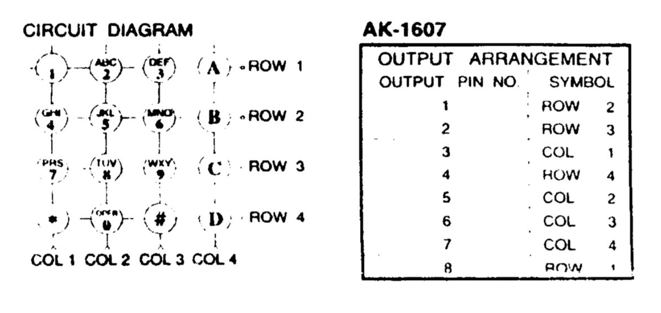
Schematics of the keypad
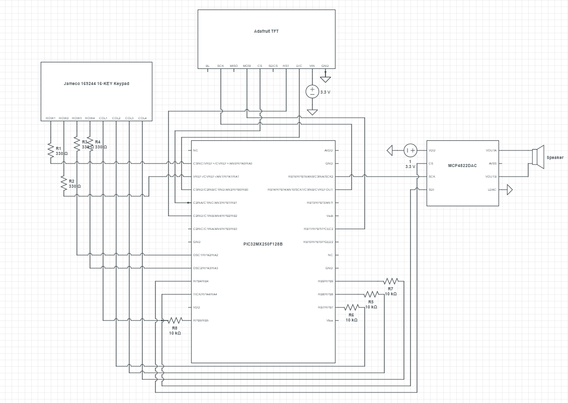
Full Schematics
C. Parts List and Cost
| Item | Model | Source | Quantity | Cost |
|---|---|---|---|---|
Microcontroller Unit |
PIC32MX250F128B |
Lab Stock |
1 |
$5.00 |
MicrostickII |
- |
1 |
Lab Stock |
$10 |
DAC |
MCP4822 |
1 |
Lab Stock |
$3.16 |
Breadboard |
- |
2 |
Lab Stock |
$3.00 |
Keypad |
Jameco 169244 |
1 |
Lab Stock |
$10.40 |
Speakers |
- |
1 |
Lab Stock |
$2 |
References top
Acknowledgements top
We would like to thank Prof.Bruce Land, Tahmid and Matt for all of their instructions and guidance throughout this semeseter. It has been a fantastic experience and we would not have achieved our goal without their help.