Introduction & System Overview
Introduction
For our final ECE 4760 project, we created a fun and competitive guitar video game using the PIC32 microcontroller. The motivation behind this project is to combine our passion for music and competitive games that can be played with friends as well as the ability to create a game that teaches the user and instrument.
Similar to the classic music games like Rock Band and Guitar hero, we use a TFT to display notes that move across the screen towards a strum region, produce guitar plucks and undertones of a song, and keep track of the user’s score. The user plays notes on a wireless mock guitar built with carbon-impregnated elastic as strings and a conducting plectrum for the guitar pick. The guitar is connected to an Arduino Uno which communicates wirelessly via Bluetooth to the PIC32. The goal of this video game is to learn the basic finger movements of holding down strings and strumming at the correct time for novice guitar players. The project can easily be extended for more advanced finger movements on the strings and strum timing for those with more experience.
Design Methods and Implementation
High-level Design overview
The game design can be broken into three distinct parts:
- Guitar construction and Bluetooth communication with the PIC
- The game design for animation, score tracking, and song generation
- The sound generation using Karplus-Strong string synthesis and DDS to two channel DAC output
The game is played using a custom wireless guitar controller. The controller is primarily made out of wood, and interfaces with the game over a Bluetooth interface. The controller is held like a normal guitar (neckstrap optional), and users can hold down frets to select the notes they want to play. They then use an included pick to "strum" the guitar.
Animation, score tracking, and song generation are accomplished in two threads in the main c program. The animation thread is ran at a constant frame rate such that the user experiences no tearing or jumping during the game but slow enough to allow for the game processing and UART communication protocol such that nothing breaks. The game thread is ran as quickly as possible to check for correct notes played and to update scoring.
The sound generation occurs in an interrupt service routine (ISR) as a sampling frequency (Fs) of 8000 Hz. The undertones are generated using sine tables and direct digital synthesis to one channel of a DAC while the string notes are generated using a Karplus-Strong String Synthesis to the second channel of the DAC.
Software Design
The Controller
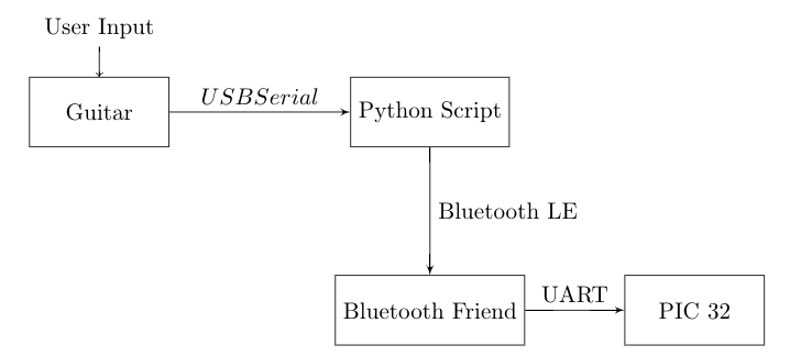
Our system uses Bluetooth LE to communicate between the guitar and the game. The Bluetooth communication occurs between a computer, and an Adafruit Bluefruit LE UART Friend. The Adafruit module serves as Bluetooth to UART adapter, taking in Bluetooth messages and converting them to a UART signal that the PIC32 can interface with.
The guitar makes use of Arduino Uno to detect strum signals. The Uno waits for a signal that denotes a strum, and then reads the strum pattern across the four strings. The strum pattern is then printed over serial, and is picked up by a computer connected over USB. On the computer, a python script is running which sends messages to a Bluetooth receiver. The script initializes by attempting to make a connection with the Adafruit Bluetooth module. Once successful, the program waits for input from the guitar. Upon receiving serial data, the data is sent over Bluetooth, where it is picked up by the module.
Once the data is picked up by the Bluetooth module, is send across the TX line of the module's UART interface. This line is connected to the RX line of the PIC32, which uses the received messages as input for the game.
Game design
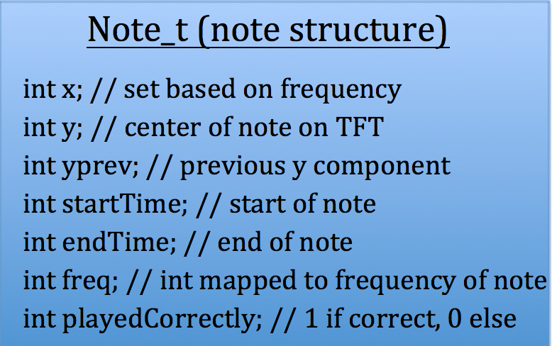
In the main function, we initialize our song Ode to Joy by correctly initializing the 60 note structures contained in the song. To do this, we individually set the startTime and endTime of each note as well as frequency. The startTime for each note is used to determine whether the note was correctly played within a userErrorTolerance value. We set the userErrorTolerance value to 200mSec to allow for ample time for the user to play the note correctly and have it register. The endTime for each note is used to determine when to move onto the next note in the sequence by incrementing a noteIndex variable. We note the x position of each note is dependent on the frequency and the initial y position is set to be off the screen at pixel y = 340. We can see the structure of each note in the following image.
Our game thread handles all scoring and checking whether the correct note is played at the correct time. We do this by checking all edge cases. The game thread also sets the correct phase increment for the current note to be played in order to correctly increment through our sine table for DDS in the ISR.
As stated in our UART communication section, once a new string pattern is communicated to the PIC32, we set strumVal to be equal to 1. If the string pattern received over UART is greater than 0, we set the stringPattern variable.
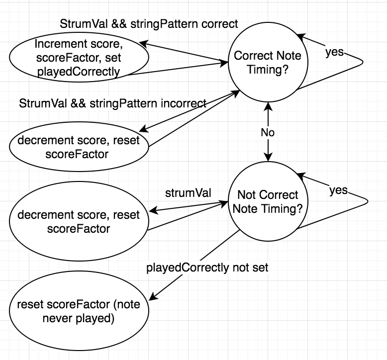
We will break up the cases for checking whether the current note is played correctly based on the currentGameTime (found by PT_GET_TIME() in milliSeconds):
- When the currentGameTime is within our note’s startTime and userErrorTolerance and strumVal is set to 1, we check whether the string pattern is equal to the correct value according to the notes frequency. This is accomplished by (stringPattern == freqToStrings(notes[noteIndex].freq)), where freqToStrings is a helper function that returns a stringPattern based on a given int freq.
If this is the current condition, we increment score by the scoreFactor and increment scoreFactor by 1 (where scoreFactor’s max value is 30) and set the current note’s playedCorrectly value to 1. strumVal is reset to 0. If the note being played is a ‘G’, the score is doubled. - The second case occurs if strumVal is set to 1 at either the wrong time (not within user tolerance) or the stringPattern is incorrect.
If this is the current condition, we reset scoreFactor to 1, strumVal to 0, and decrement the score by 2 (where the minimum score is 0). - The third case occurs if the currentGameTime is greater than the startTime of the note plus the userErrorTolerance.
If this is the current condition AND the current’s note playedCorrectly value is not set that means the user never played the correct note. If this is the case we reset scoreFactor and decrement the score. - The last case occurs if the note’s endTime is less than the currentGameTime. If this is the case, we increment the noteIndex by 1 and reset all variables related to the Karplus-Sound sound generation. We then reset the given notes white noise sound buffer for the next time it is played.
The cases above are shown in the game logic block diagram, which represents the states we will be in during the game. Note at all points in the game we are either in a correct or incorrect time period, and in each of those periods, we continuously check the other conditions previously mentioned.
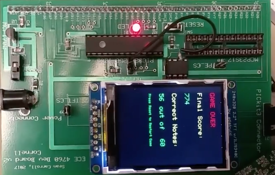
Once the last note is played, the game state enters a final score display screen as pictured and waits until the user restarts the game. The final display screen shows the correct number of notes played out of the total possible, the final score, and prompts the user to restart the game if he or she decides to play again.
Animation
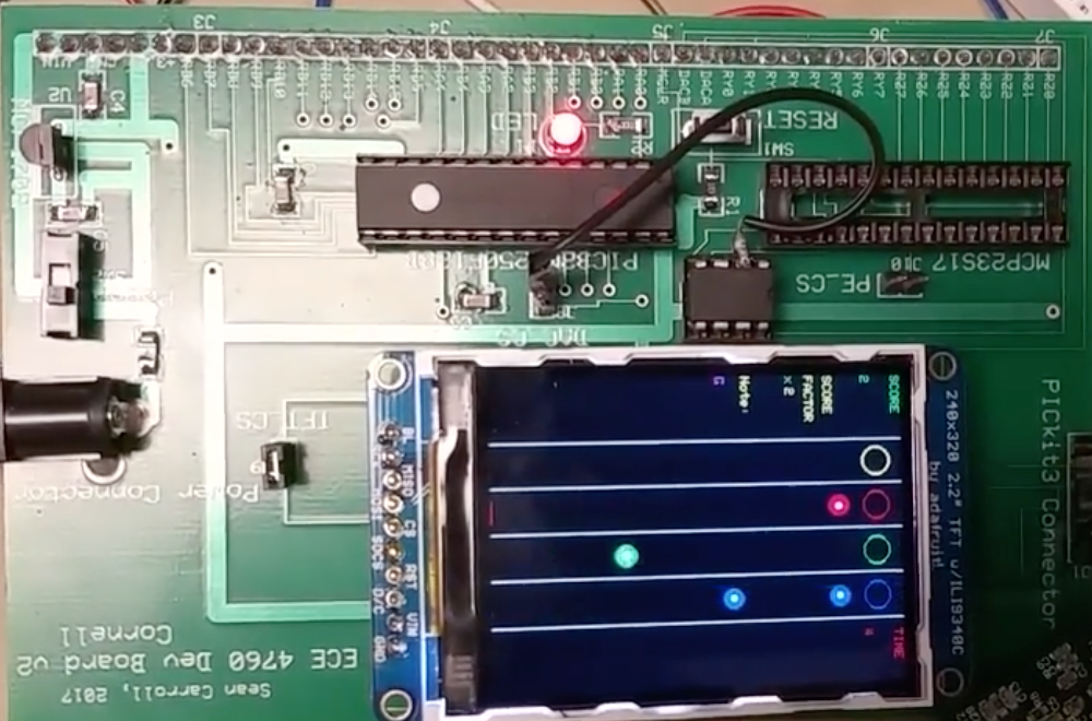
In the main function, we initialize the TFT, set it for 240x320 resolution, and initialize the game pixels using tft_initGamePixels();. The initialized pixels mimic and guitar, such that when the notes hover over a strum region, the user should strum the correct strings. We display the score, scoreFactor and currentGameTime on the sides of the TFT. We also display the current stringPattern to the character note by using a helper function stringsToNote.
In order to successfully eliminate and tearing in the display or notes jumping, we had a hard requirement of 15 FPS for drawing the notes and updating the scoring metrics. The final design allowed for a constant 16+ FPS by yielding as follows: PT_YIELD_TIME_msec(62-(PT_GET_TIME()-begin_time)) ; // 16+ hz constant frame rate. Where the begin\_time is the time we enter the animation thread.
Each time we enter the animation thread, we must update the y position of the next four notes to be played by the user. In order to accurately do this and provide the user enough time to digest the next note, we do the following calculation:
The two animation screens are shown in the following images as well as throughout the live video demo.
for (i = 0; i<4; i++){
  notes[noteIndex+i].yprev = notes[noteIndex+i].y;
  notes[noteIndex+i].y = 20 - ((currentGameTime-notes[noteIndex+i].startTime)/10);
}
This calculation ensures the note’s y position when currentGameTime equals startTime is 20. We erase the previous animation of the note by tracking yprev before y is updated. We then draw the next four notes and color each according to frequency as follows: ‘C’ = YELLOW; ‘D’ = RED; ‘E’ = GREEN; ‘F’ = BLUE; ‘G’ = RED & BLUE.
Sound generation
Sound is generated using Direct Digital Synthesis (DDS) for the undertones of each note and Karplus-Strong String Synthesis for the guitar plucking noise when a note is played correctly. The sound is outputted on a two-channel speaker using two lines (A for undertones and B for Karplus-Strong) of a DAC. We write to both lines of the DAC through SPI. All sound is generated in an interrupt service routine (ISR) running at 8 KHz based on Timer2.
Our configuration includes setting a toggle rate of 5000, which allows us to have a DDS sample rate of 8kHz on a 40MHz clock. We also connect the timer to our DDS logic ISR. After handling the timer, we configure the SPI output by configuring the proper PPSOutput and digital output pins on port b, and then opening the SPI channel. We set Timer2 up by first opening it to interrupt at 5000 cycles, configuring it, and clearing the interrupt flag as follows:
OpenTimer2(T2_ON | T2_SOURCE_INT | T2_PS_1_1, 5000);
// set up timer with priority 1
ConfigIntTimer2(T2_INT_ON | T2_INT_PRIOR_1);
mT2ClearIntFlag(); // clear interrupt flag
For the undertones, we loop through a 256 entry sine table using a 32-bit phaser. Because the sine table is only 256 entries long, we use bit shifting to get the top 8 bits of the phaser before doing a lookup. The phaser increment value if determined by phase_incr_main = Fout*(float)two32/Fs; where Fs is our sampling rate of 8 KHz, and Fout is our desired output frequency. Our phase_incr_main is added to an accumulator variable, phase_accum_main. Fout is changed based on the current note the user is supposed to play, regardless of whether the note is played correctly. This allows for audio feedback is the note is played incorrectly or if the user is unable to visually determine the note that should be played.
We also linearly modulate the amplitude of the sound from 0 to 1 at the start of each note in order to avoid any annoying clicking at the start of end of a note. We chose linearly ramping due to the simplicity of the calculation and to maintain a nearly continuous sound for the user. The undertone is outputted to DAC_A_data and played on one channel of a lab speaker.
For the acoustic guitar string plucking, the basic filter for a Karplus-Strong implementation can be visually by the block diagram as shown below. We implemented this for each note using fix16 arithmetic to utilize fewer CPU cycles in the interrupt. An example of the C implementation of this filter is as follows:

DAC_B_data = (C_table[pluckIndexIn]>>16);  // sample out, fix16 to int
lowpass_out = multfix16(damping, ((C_table[pluckIndexIn]) + (C_table[pluckIndexOut]))>>1);
//replace current pluckIndexIn with new time-delayed averaged value with tuning constant
C_table[pluckIndexIn] = multfix16(tune,(lowpass_out - last_tune_out)) + last_tune_in;
// all-pass state vars
last_tune_out = C_table[pluckIndexIn];
last_tune_in = lowpass_out;
Each notes table is originally set to white noise, where the tune controls the type of sound that is outputted. We set tune to 0.14 and no dampening (damping = 1) to allow the note to play continuously until it is over and sound like an acoustic guitar. The frequency of the note determines the correct amount of delay we require for each update cycle. Whenever a note is finished, its circular buffer array is refilled with white noise for the next time it may be played.
Hardware Design
The Controller
One of the most exciting parts of this project is the physical guitar controller. The controller was designed to mimic the natural motion of playing a guitar as closely as possible. We broke down that motion on a real guitar into two parts. First, a user selects the sound they want to play by holding the appropriate strings down. Second, the user plays the sound by strumming the strings. To have a controller that resembled a real guitar, we wanted to abide by those two intuitive motions.
At the top of the guitar controller is the fret board. This is where the user is able to select the sound they want to play. Throughout the system, the sound is represented as a nibble (4-bits), so we use 4 strings to select the sound.
Each string works as an active-low push-button. The strings themselves are made of carbon-impregnated elastic, which feels and moves like elastic but is also conductive. Each string was also wrapped in 30 gauge copper wire to ensure solid contact with any conductive surfaces. The strings are each connected to screws, which run through the fret board and connect the strings to the the fret circuit.
The purpose of the fret circuit is to detect changes in voltage across 4 lines. Each line is branched off of a power rail, and connected across a string to an input pin on an Arduino Uno. Without interference, current runs from the power rail across each string to its respective input pin, which reads a HIGH signal. In order to detect a push on the string, we grounded the surface that the string is pushed into. By wrapping the fret board in a grounded conductive pad (aluminum foil), and pushing the string into the fret board, we are able to ground our signal before it can reach the input pin. When this occurs, the associated pin reads a LOW signal, which is interpreted as a press of the string by our system.
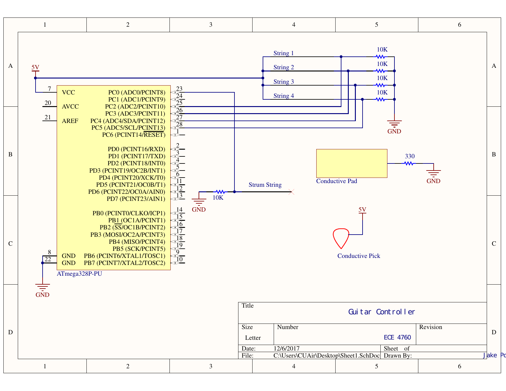
Along with the fret circuit, we also needed a way to detect strums. The strum circuit is very similar in its use of a copper-wrapper carbon-impregnated elastic string. The string is connected through the fret board to an input pin on the Arduino, but is not powered. Without any external contact, the pin reads LOW. When voltage is applied to the string, the pin reads HIGH, detecting the strum. In order to mimic the strumming motion most accurately, we use a guitar pick to apply the voltage to the string. The pick is wrapped in a conductive material, which is connected to the power rail. Contact of the pick applies voltage to the string, which on a rising edge denotes a strum.
PIC32 Bluetooth connection
The connection between the Bluetooth LE and PIC32 requires only one line as well as power and ground to the Bluetooth LE. The data is sent across the LE's TX line of the module's UART interface and then this line is connected to the RX line of the PIC32, which uses the received messages as input for the game.
DAC output
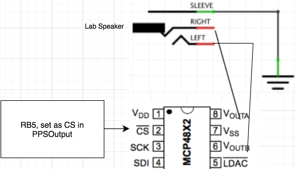
The hardware setup for the DAC output is fairly straightforward. Given the DACA and DACB outputs onthe big board, we connect these directly to the left and right channels of a lab speaker and connect the sleeve to ground, as shown in our dac output figure.
Testing Methods and Debugging
We utilized unit testing for each component of the lab in order to ensure that every part of the lab worked separately. We then combined each of these components and tested edge cases to ensure the implementation worked according to the specifications we set out to fulfill. This section contains a detailed description of all testing methods used for each individual component of the implementation and optimization and how we fixed bugs caught during testing.
Firstly, we constructed the physical set-up of the mock guitar using carbon-impregnated elastic and a conducting plectrum connected to an Arduino Uno. We tested the physical set-up by first making a mock out of cardboard in order to test the length and width for user comfort. After prototyping the design, we made modifications and then constructed the final guitar out of 1/8-inch plywood, carbon-impregnated elastic for strings, and a conducting spectrum.
Secondly, we tested the note structures animation and timing visually to ensure that the notes would appear giving ample time to the user to play the note correctly and enter the strum region of the TFT at the correct time. We caught timing and display errors and corrected the physics and display of the note movement accordingly.
Thirdly, the song construction and note structures were tested by printing values to the TFT and debugging according to the specification. By using this method, we caught timing errors when updating the note index of the song and corrected them accordingly.
Fourthly, we tested the sound generation using the oscilloscope on the DAC as well as listening to the undertones. By listening, we could change the fine tuning and dampening of the string generation in order to more closely resemble the frequency and sound of an acoustic guitar.
Finally, we tested the Bluetooth communication between the Arduino Uno and the Adafruit Bluefruit LE UART friend to the PIC32 and caught additional timing errors for updating the strum value. In order to correct these issues, we modified the UART library to correctly update our strum value at the proper game times.
Results
Demo Video
Timing Accuracy and Frequency tuning
The final game-play runs constantly at a little over 16 FPS and shows no tearing or jumping in notes, scoring, or timing on the display. The scoreFactor updates consistently and accurately when notes are played correctly, an incorrect note is played, or there is no strum by the correct time. When playing a note that requires two strings at once, double score is added correctly. Overall, the game is easily learned however it is difficult for a novice guitar player. This successfully completed our goal of teaching someone who never has played guitar how to move his or her fingers and strum at the correct time. For example, when Jonah first played he scored just 7 notes. After the second try, he successfully scored 33/60 notes. Jake Podell similarly struggled in the beginning. As he was the main tester for the physical guitar, during his demo play through of Ode to Joy, he successfully played 56/60 notes correctly.
The frequencies of our undertone for each of the five notes (C4, D4, E4, F4, G4) have errors of less than 1% according to measurements from the oscilloscope, which can be attributed to noise in the DAC output. The errors for frequencies from the Karplus-Strong String Synthesis vary for the given note due to limitations in the sampling frequency. Because we are only running at 8 KHz in order to maintain a high frame rate for user experience, the circular buffer used for G4 (as an example) contains only 20 elements. We note the frequency can be calculated as Fs/(Buffer length). This is a trade-off we were willing to take as we had a hard requirement in not allowing any tearing or jumping in the note animation thread in order to enhance user experience. We will happily have a max error of 2% for the synthsized frequency in order to allow this. The synthesized frequency in relation to the notes natural frequency and percent error are shown in the table below.
| Note | Natural Freq (Hz) | Synth Freq. (Hz) | Error Percent |
|---|---|---|---|
| C4 | 261.6 | 258.0 | 1.4 |
| D4 | 293.7 | 296.2 | 0.8 |
| E4 | 329.6 | 333.3 | 1.1 |
| F4 | 349.2 | 347.8 | 1.4 |
| G4 | 392.0 | 400.0 | 2.0 |
The time taken to connect from the python script to the module averages to 8 seconds. This is the mean taken over 20 trials, which included no significant outliers. We wanted to test the latency between a strum on the guitar and the reponse of the system, but it occured to quickly for testing. This was a pleasant surprise as the userErrorTolerance far outweighed any latency caused by bluetooth communication from the Arduino to the Bluetooth LE and then sent to the PIC32 via UART. Because of this, our final project worked effectively within all time constraints specified in the game design.
Conclusion
We set out to create a fun video game designed to teach the user the basic hand movements of playing a guitar. Our end result was a successful, functional video game that allowed the user to play various note patterns for our implementation of Ode to Joy. The scoring component and error noise create a competitive and educational feature that encourages the user to get better through audiovisual feedback.
Future Improvements
There are many opportunities to implement further functionalities in the game. While we found a good medium for the user tolerance error in game, adding a feature that allows the user to choose the difficulty would be feasible in our current implementation. For our demo, we showed the possibility of playing two strings at once to represent another note. This feature can be extended for multiple notes being played at the same time by simply adding and averaging the components of their Karplus-Strong circular buffers. There are also opportunities in extending the implementation of the mock guitar. While we used carbon-impregnated elastic to create a connection for the strings and strumming, there is a possible extension to allow fretting on the same string by measuring the resistance change when stretched.
Conforming to Standards
The Adafruit Bluefruit LE UART friend conforms to all FCC requirements for a bluetooth device. Otherwise, our project conformed to the standards as set up by the IEEE code of ethics, copyright law, and our specifications for the development process as described in the following sections.
Intellectual Property Considerations
We ensured to not breach any intellectual property during the development of our video game. All code not individually developed for this project specifically is either public source or available through the ece 4760 course materials and referenced whenever used.
The song used for our game, Ode to Joy, is public domain and therefore there are no copyright issues as the copyright of any originally composed song expires 70 years after the death of the composer. We also note that while games such as Guitar Hero and Rock Band exist, game mechanics are not protected under copyright law and therefore we are not worried about the similarities to our note strumming region to that of already developed video games.
The script used to connect the guitar to the Bluetooth module uses Adafruit's Bluetooth LE code. This includes their libraries for use with the module, and many examples that we used as inspiration when making our own script.
Ethical Considerations
Our project design and implementation decisions we made throughout were consistent with the IEEE Code of Ethics. We undertook this project in order to improve our technical competence while sharing our completed projects with those who are not familiar with microcontrollers or the possible use cases of this technology. Throughout the project we worked as partners assisting each other with every task in order to learn and keep track of the project as a whole. In the initial project proposal, we were honest and realistic in stating the features we would implement and the estimated time it would take to complete in our timeline.
For the design implementation, we specifically wanted both audio and visual feedback mechanisms while the user is player such that someone who is either blind or deaf could also play our video game successfully. We also maintained voltage limitations on the construction of our mock guitar so the user would be safe and not be shocked while strumming or holding down the strings. Every week throughout the implementation of our design, we sought out criticism and advice from peers, teaching assistants, and Bruce, accepted this advice, and corrected errors in the design. We credited all sources we utilized throughout the development of this project in the references section as well as throughout the report.
Legal Considerations
Our project utilizes Protothreads by Adam Dunkels which is copyrighted but available for all commercialand non-commercial use with proper citation. We cite this usage in our references as well as at any pertinentpoint in the source code.
As stated in our IP considerations section, we do not believe we are at risk of any sort of lawsuit as all game mechanics were developed individually and, even though game mechanics can not be copyrighted, ours are unique.
We also note that the bluetooth Adafruit BlueFruit LE is FCC/CE approved and does not require approval to integrate within personal projects with no modification to the circuit. Therefore, we are within the legal requirements for our bluetooth communication.
Appendix A: Inclusion Approval
The group approves this report for inclusion on the course website.
The group approves the video for inclusion on the course youtube channel.
Appendix B: Parts Cost
| Part Name | Unit Price | Total Units | Total Price |
|---|---|---|---|
| PIC32 | $5 | 1 | $5 |
| MicroStick 2 | $1 | 1 | $1 |
| White board | $6 | 1 | $6 |
| TFT LCD | $10 | 1 | $10 |
| Lab Speakers | $2 | 2 | $4 |
| Power Supply | $5 | 1 | $5 |
| Jumper Cables | $0.10 | 20 | $2.00 |
| 1/8 inch 2x4 plywood (HomeDepot) | $7 | 1 | $7 |
| Adafruit Bluefruit LE UART Friend | $17.50 | 1 | $17.50 |
| Arduino Uno | $12 | 1 | $12 |
| Carbon-Impregnated Elastic | Lab Surplus | 1/2 meter | $0 |
| Resistors and wires | Lab Surplus | N/A | $0 |
| Total Cost | $69.50 |
Appendix C: Code Listing
The C code running on the PIC32The python script for bluetooth communication
The guitar controller code running on the arduino
Appendix D: Schematics
Appendix E: Work Distribution
Both partners contributed equally in the conception and high level design of the final project. Jake and Jonah worked closely together in dividing up sub-tasks for the project. While working in lab together, we worked closely together on each part of the project, alternating who was ”driving” (doing the typing on software, connecting circuits, debugging, etc.). While we did most of the implementation together while in lab, we split up the project into smaller sub-tasks that one of us was in charge of. Jake took a lead on the physical guitar construction and communication between the guitar and PIC. Jake was in charge of the design for the Bluetooth and UART communication protocols as well as how the userwould interact with the mock guitar. Jonah took a lead of the game design and sound generation. Jonah was in charge of implementing Karplus-Strong string synthesis, the game animation on the TFT, and how to accurately store songs in notes. He was in charge of making the hardware and software decisions for these aspects, sharing his decisions with Jake. The same kind of decisions-discussion-implementation flow was applied to the parts that Jake was in charge of. While we were responsible for the initial decisions on certain parts individually, we were both equally responsible for the final design, debugging, and testing of every aspect of the lab.
Appendix F: References
Datasheets
PIC32MX250F128B Datasheet: http://www.microchip.com/wwwproducts/en/PIC32MX250F128BPIC32
Hardware manual: http://people.ece.cornell.edu/land/courses/ece4760/PIC32/indexRefMan.html
Protothreads by Adam Dunkels: http://dunkels.com/adam/pt/
The SPI DAC datasheet: http://people.ece.cornell.edu/land/courses/ece4760/labs/f2017/lab2mcp4822.pdf
Arduino Uno datasheets: https://store.arduino.cc/usa/arduino-uno-rev3
Adafruit Bluetooth library: https://learn.adafruit.com/introducing-the-adafruit-bluefruit-le-uart-friend/downloads
UART: http://people.ece.cornell.edu/land/courses/ece4760/PIC32/indexUART.html
Legal considerations for videogames according to U.S. copyright: https://gamedev.stackexchange.com/questions/1653/how-closely-can-a-game-legally-resemble-another
History of video game clones and legal repercussions: https://en.wikipedia.org/wiki/Videogameclone
Copyright of music: https://www.copyright.gov/circs/circ15a.pdf
Project Background
Note frequencies: https://pages.mtu.edu/~suits/notefreqs.htmlOde to Joy Sheet Music: http://www.music-scores.com/midi.php?sheetmusic=BeethovenOdetoJoyeasy
Karplus-Strong basic implementation: http://crypto.stanford.edu/~blynn/sound/karplusstrong.html
ECE 4760 Karplus-Strong avrDSP implementation: http://people.ece.cornell.edu/land/courses/ece4760/Math/avrDSP.htm
IEEE Code of Ethics: https://www.ieee.org/about/corporate/governance/p7-8.html