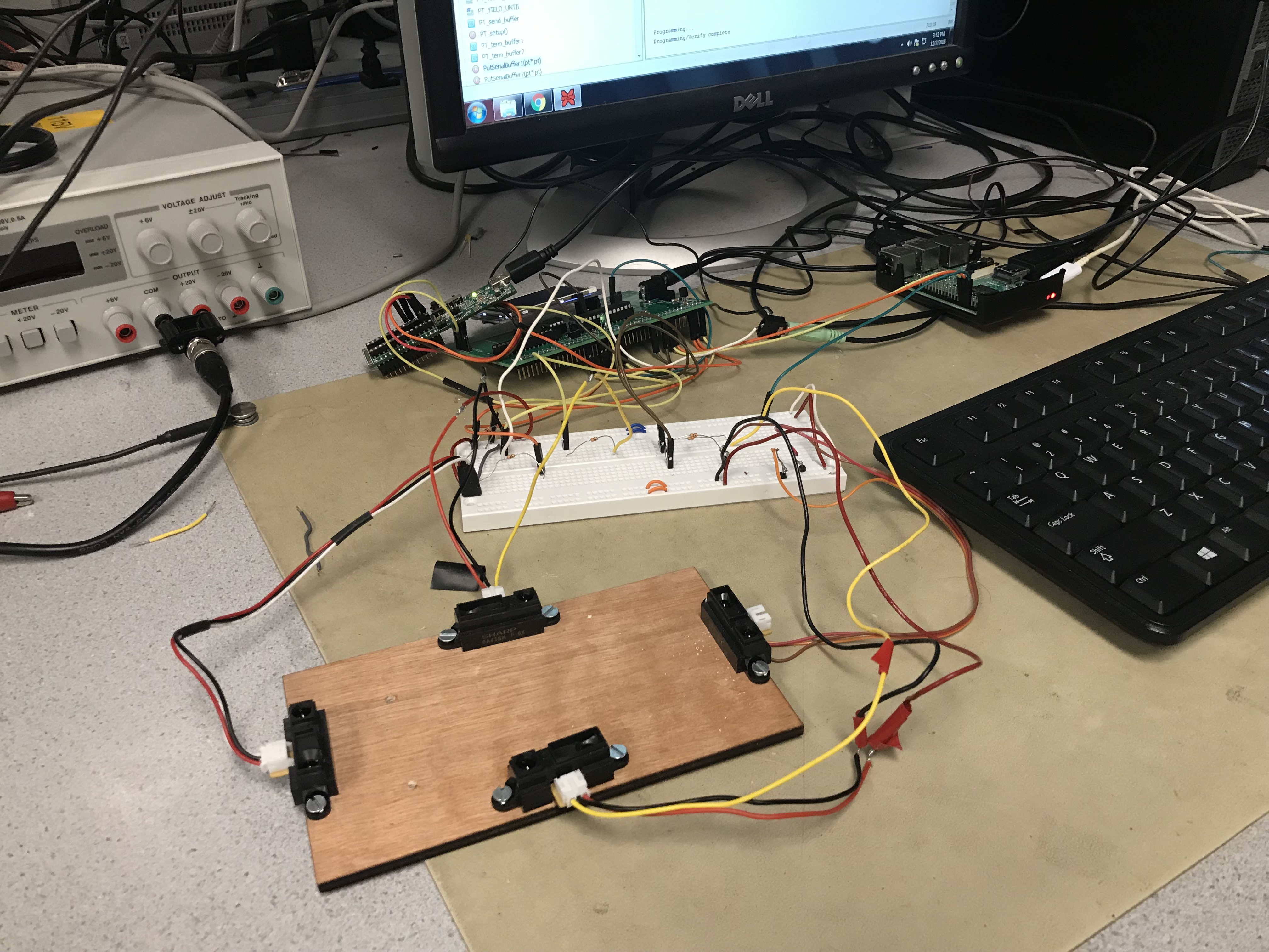
Figure 1: Motion Sensor Speaker Hardware
Introduction
The Motion Sensor Speaker is an application that uses sensors to control the audio output from a speaker based on patterns that the sensors detect. This idea stemmed from us wanting to be able to change songs without having to physically touch the playback device. We wanted to see if we could build a prototype of this type of technology using IR sensors, the PIC32 Microcontroller, and another main component that would be based on whether we decided to stream the music or play it back from a memory device that it was downloaded to.
After much research and some attempts to play from alternate methods, we decided to use one of our member's Raspberry Pi 3 as a device to playback the songs from. By the end of the semester, using the IR sensors, PIC32, and Raspberry Pi 3, we were able to build a working prototype that was able to pause and play songs, turn up and down the volume, and change to the previous and next songs, solely based on the activation of different combinations of sensors.
High Level Design
This project idea was incepted when we began to talk of innovations that would be interesting to us and that we could see being implemented into products in the near future. We all had an interest in music and could definitely see motion sensing applications being built into products such as Smart Watches and other similar smart products that have streaming capabilities.
We immediately took a liking to this topic as we all found a personal interest in this type of technology, and also saw this as something that could be part of a project that we work on in a professional setting. It could definitely be useful to work on a product that would fit into the hands-free technology trend that we have seen in the electronics sector recently.
A significant mathematical part of our project was the communication between the Raspberry Pi and the PIC32, through the utilization of their Universal Asynchronous Receiver Transmitter, or UART hardware. The serial port between the two was set up at a baud rate of 115,200 Bps as this was the fastest speed that the serial port was able to transfer data between the two computers.
The baud rate is the speed at which bits can be transferred, so bytes of data can be sent at a max rate of 14,400 Hertz. Therefore, we had to downsample most tracks of music as they were sampled at a rate of 44,100 Hz. We used a matlab code that was provided by the professor to downsample the tracks to a quarter of that frequency, or 11,025 Hz, as this was the greatest rate we could obtain that was below the max. This decreased the quality of the relayed music, but it was still good enough to be enjoyable for the most part. The structure of our project is as follows: we begin by programming or resetting the PIC32 and running our code on the Raspberry Pi 3. Once the PIC has finished programming it will send a ready signal to the Pi. The Pi receives this signal and then begins to process and send the music data that has been written onto it, byte by byte. These bytes are received by the PIC and stored into two buffers, one for reception, then copied into another one for playback. Once one of the buffers is full, it sends a signal that it is ready to receive more data. Look to the [Logical Structure figure] for an illustration of this process.
There were a couple of tradeoffs we had to consider regarding the hardware and software. As mentioned earlier, the devices we used had a maximum baud rate so this limited the speed at which we could transfer each byte of data. The PIC32 had limited amount of memory on it so we had to optimize the code in order to use the least amount of storage as possible, and elected to only store 8kB at a time throughout the data transfer. Another benefit of the Raspberry Pi was that it only took 2 pins in order to work as we found ourselves running low on the remaining free pins left on the PIC32. This prevented us from using an SD card to store more data on the PIC32 as it required using some pins that were already in use.
We made sure to follow the typical multi-processor communication protocol that was relevant for our purposes. Since we were using the UART hardware present on the PIC and the Pi, we had to follow the RS-232 standard. This can be seen in our connection of the two receiver and transmitter pairs, with the Raspberry Pi serving as the data terminal equipment or DTE and the PIC as the data communication equipment of DCE. We followed the typical RS-232 communication format for PCs, which consisted of a start bit, 8 data bits, no parity bits, and a stop bit. By convention, the start bit is set low and the stop bit is high. We set the speed to the highest baud rate available, 115.2 Kbps.
Currently, Motion Activated Sound Players are being produced by a variety of vendors, but these are being used for a purpose that is different from ours. These products are generally used as some sort of greeter or alert, and just play a preprogrammed noise as soon as motion is detected near the sensor. Our project is more focused around using motion to control a sound or music playback device, and different patterns of motion are supposed to lead to different results. Therefore, patents, copyrights, and trademarks garnered by these type of products should not be considered relevant to our product even though we share a basic premise in the motion activated speakers.
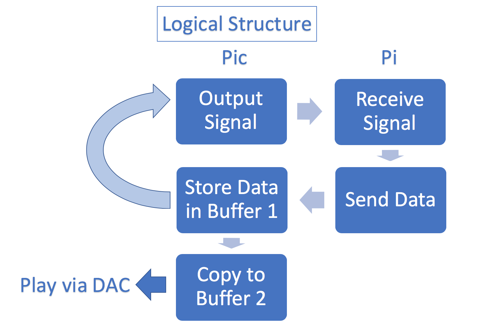
Figure 2: Logical Structure Diagram
Program/Hardware Design
Hardware Design
To design the hardware side of our system we started with creating circuits on a whiteboard using wires and passive components, such as resistors, to set up. We use the whiteboard as the interface between the PIC32 microcontroller and the IR distance sensors, including connecting common grounds and to supply voltage to the IR sensors. We also built a platform to hold the IR distance sensors in their desired positions. This makes it easier to control the system using your hands due to the separation and stability of the sensors.
Since our PIC32 does not have enough space in memory (only 128 KB of Flash memory) to store full songs, we needed to an external device to store music and stream to the PIC32. We chose to use a Raspberry Pi Model B for this task since its memory is only limited by the memory card that it is using, and it is a very high-performance device for its price. We decided to use serial communication to communicate between the PIC32 and the Raspberry Pi due to a lack of pins available on the big board and the capability of both the Pi and PIC to communicate at a fast enough rate to stream music at a 11 KHz sampling frequency using this protocol. This required connecting the UART transmit pin on the PIC32 to the UART receive pin on the Raspberry Pi, and vice versa. We also connected the grounds together to make sure they share a common ground.
Circuitry
We use a breadboard as the interface between the different parts of our system (PIC32, Raspberry Pi, and IR distance sensors). We start by connecting the ground and 5V Vin pins to the both bus strips on the breadboard. This gives us a power and ground rail on each side of the breadboard. For each of the four sensors we solder wires to their three pins (output voltage pin, supply voltage pin, and ground pin). We then connect the wires soldered to the ground and supply voltage pins to the breadboard's ground and power rails, respectively. The voltage output pin, which outputs an analog signal, is then connected to one end of a 300 Ohm resistor, while a wire is connected from the other end to the correct analog pin on the PIC32. The purpose of this resistor is to limit the amount of current entering the analog pin, which can hurt the PIC32. We also use the breadboard to connect the DAC A output to the analog input pin on the audio jack. The speaker's auxiliary cord can then be inserted into the audio jack to receive the converted data.
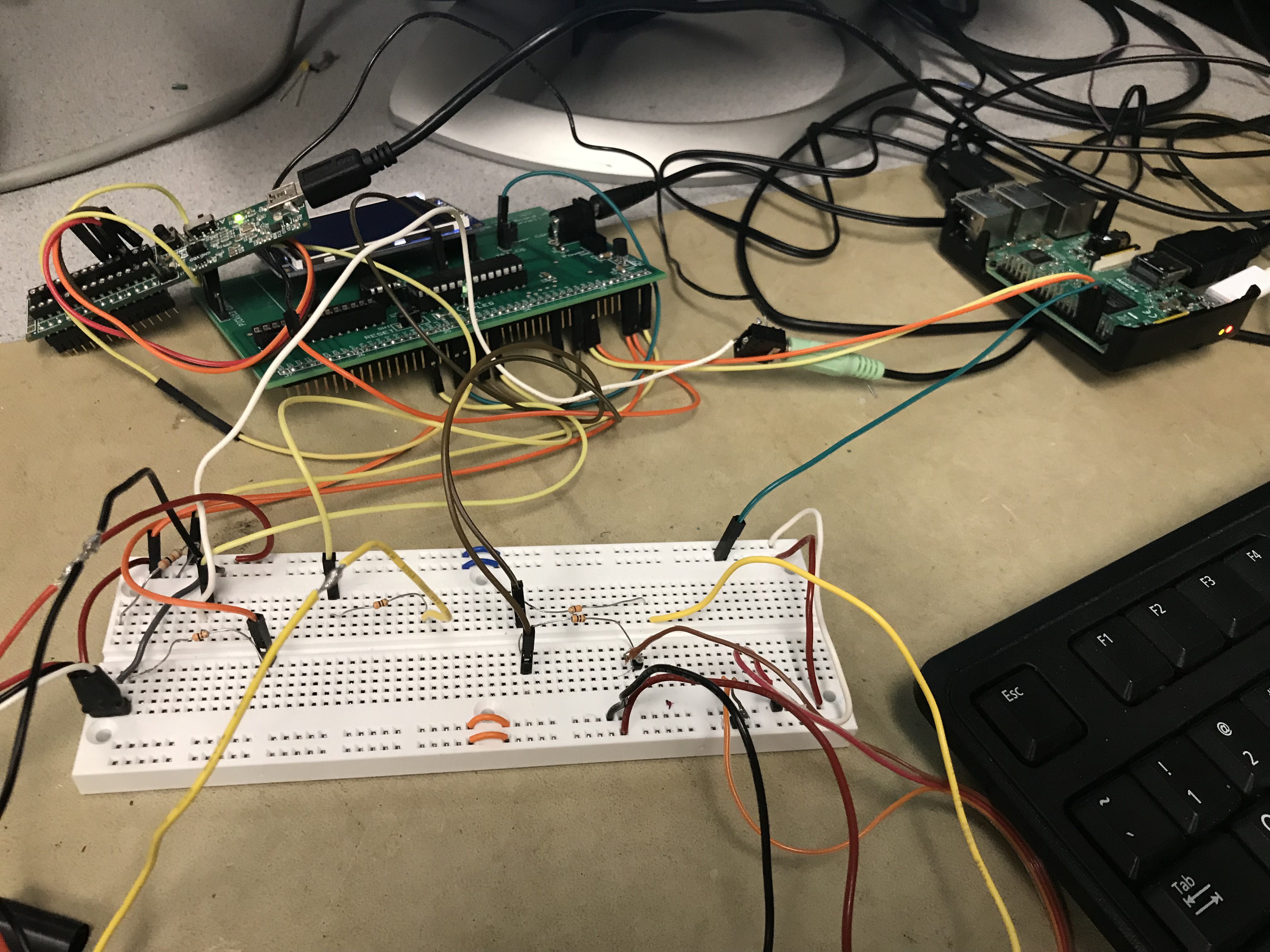
Figure 3: Circuitry on Whiteboard
Sensor Array
This sensor array acts as the interface between a human and the music streaming system that we designed. We screwed the sensors to a small rectangular wooden board to keep them stable and make it easy to control the program using your hands. We choice to assemble the sensors in a diamond formation (one at the bottom of the board, one at the top of the board, one at the right side of the board, and one at the left side of the board). This formation makes it easy to control the flow of the music by simply holding your hand over different combinations of sensors to perform different actions (i.e. holding your hand over the bottom and top sensor pauses or resumes playing the music). The diamond formation also makes it possible to add a swiping feature to our system in the future. For example: swiping across the sensors from left to the right will switch the music to the next track.
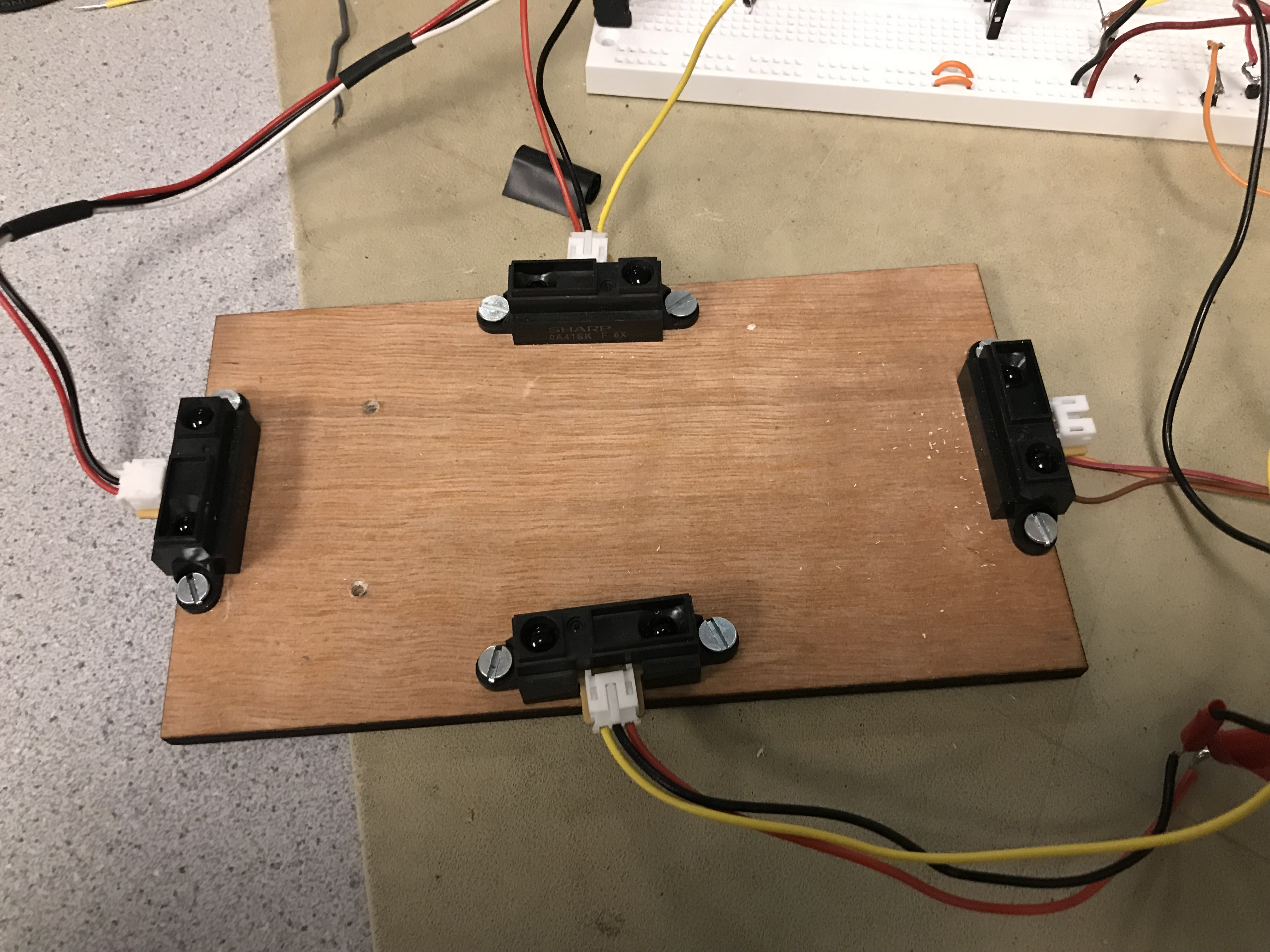
Figure 4: Sensors board
UART Serial Communication
To communicate between the Raspberry Pi and the PIC32 we utilize both of their UART modules. UART uses a protocol that communicates information between microcontrollers, one byte at a time. Before the first bit is sent, a start bit is sent to signal the start of a new byte. After the last bit of the byte is sent, a stop bit is sent that signals the end of the byte. Both the Raspberry Pi and PIC32 transmit information from the UART module through a transmit pin Tx. On the PIC32 we map this output to pin RPB9, while it is mapped to GPIO14 on the Raspberry Pi. The pin that receives the transmitted data, Rx, is mapped to RPB8 on the PIC32 and GPIO15 on the Raspberry Pi. After connecting the Tx pin on the Pi to the Rx pin on the PIC32 and the Rx pin on the Pi to the Tx pin on PIC32 (and connecting both of their grounds), they are able to communicate with each other.
Program Design
The main software component of our motion sensor speaker system consists of two threads and an interrupt service routine on the PIC32 and a Python program on the Raspberry Pi that continuously execute until the program is terminated. The threads, ISR and Raspberry Pi program must be synchronized with each other and communicating efficiently for the entire system to run successfully. The sensor thread reads the analog input from the analog IR distance sensors and controls the state of the system based on this data. The serial thread's main function is to spawn another thread that reads and sends data through the UART module based on the state of the system. The interrupt service routine processes data received through the UART and outputs the processed data through the DAC. The serial communication program run on the Raspberry Pi loads the music header files and sends this data through UART. This program also receives data through the UART from the PIC32 that affects the state of the program.
Another important program that must be executed is the WAV to Header conversion MATLAB program. This program converts WAV music to a format that is compatible with the rest of our program before being transmitted from the Raspberry Pi to the PIC32. This program must first be executed in order to play a new track. Together, combined with the C header files provided by the Bruce Land, these programs compose the software side of our system.
Sensor Thread
This thread starts off by reading the first four channels of analog-to-digital convertor (ADC). The ADC converts the analog output from the four IR distance sensors to a digital format that is then stored in variables (adc_9, adc_10, adc_11, adc_12). We set a minimum threshold of 400 ADC units for a sensor reading that counts as a valid detection. We found this to be an ideal threshold through trial and error. If the threshold is too large, then you have to hold your hand too close to the sensor to be detected. If it is too large, then objects that are far away may be unintentionally detected.
We implement a counter for each sensor to keep track of how long a hand is being detected by a sensor. Each counter is incremented every consecutive iteration of this thread that a hand is still being detected by the same sensor. If a sensor no longer detects a hand, then its corresponding counter is reset to zero. These counters are a form of debouncing the sensors. For example: if someone quickly waves their hand over a sensor by accident, then it will not be acknowledged by our program.
These counters act as the control signal for the state of the music playback. They also signal actions that should be done to the playback. The two states that our system can be in are play and pause. When someone holds their hand over the bottom and top sensors, the state is switched to the other state (i.e. state switches from play to pause of pause to play). We found that if the top counter is equal to three and the bottom counter is greater than one, then it is a solid enough sign that someone is attempting to either resume playing music or pause the music. We discovered that when we set the condition for both counters to be equal to the same value, the switch of states was inconsistent. The volume of the music can be turned up or down when a hand is held over the top or bottom sensor, respectively. To adjust the volume, the counter corresponding to the sensor must be equal to two and the sensor opposite it must be less than one. We added the less than one condition to differentiate this action from changing the play/pause state. A variable for volume is then decremented/incremented based on which action is signaled. We also implemented an action state for switching to a new song. When a hand is held over the right or left sensor, the next/previous track should played. This thread sets the action variable to next or previous track if either of these counters is equal to two. The desire to switch tracks is later signaled to the Raspberry Pi by a the serial thread.
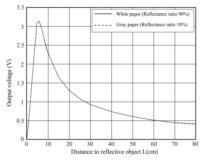
Figure 5: IR Sensor Voltage Graph
Serial Thread
This thread spawns another thread that communicates with the Raspberry Pi by sending and receiving data through the UART Tx and Rx pins. Each byte of data is received by the PIC and stored into one of the buffers, while the other one is being read in the ISR. We use two buffers so that there is constant playback as we have one buffer constantly receiving the data and the other relaying that data to the DAC. This is more efficient and necessary so that data can be received and written at the same time that data is being played, allowing for a seamless transition between each byte of music data that is transferred. The spawned thread is not killed until the current buffer being written to has been filled with the latest 8,000 samples of the transmitted music data.
In the spawned thread, we continuously check the state of our system and send a signal to the Pi based on this state. When the state of our system is in play we continuously receive data from the Pi by first sending it the ready signal, and when the state is in pause we stop sending the ready signal, which stops the transfer of data, but we make sure to save the spot that we stopped at on both ends. When switching to the next or previous track we output the corresponding signal that basically informs the Pi to begin outputting data from the next or previous set of data that was downloaded (each set is given a corresponding number on the Pi side). The next or previous signal is only sent once, then we return to continuously sending the ready signal so that the PIC in turn receives and plays the song immediately, making the entire song switching process occur in real time. We have to make sure to clear the buffers when necessary, such as when switching songs, so that playback of different song data does not overlap, an issue that we encountered briefly.
Python Serial Communication Program
This program's main purpose is to transmit music samples to the PIC32 using serial communication. It reads and writes serial data through the UART module on the Raspberry Pi. The program begins by initializing a serial writer and reader to send and read signals through UART. We set the baud rate for this communication to 115,200 bits per second (fast enough to transmit 14.4 thousand samples per second). We then read the read the header files into variables, which we convert to integer format. One final conversion is then done to the data, as it is converted to bytearrays format. At this point, the music samples are able to be transmitted through the Raspberry Pi's UART transmit pin.
Once the initial procedures done on the data are completed, the program enters an infinite loop and begins reading the serial input. If an 'A' is received, then a flag is set to indicate that the PIC32 is waiting to receive data. Once this flag is set, the next 8,000 samples of the current song being played is transmitted through the Pi's transmit pin to the PIC32. If the song is finished being transmitted, then on the next iteration the next song starts being transmitted to the PIC32. If an 'N' (or 'P') is received instead, the next (or previous) song read by the program starts to be transmitted. Our current python serial communication program only transmits three songs, but this program can be expanded to transmit many more songs by simply converting and loading more WAV files onto the Raspberry Pi's memory. It will also require duplicating much of the code.
Interrupt Service Routine
This ISR converts the samples in the serial buffers before being transmitted through the second SPI channel and output through the DAC. This ISR is triggered by a timer interrupt at a rate determined by the sampling frequency of the music playback. We set the timer to trigger an interrupt every 3,628 cycles (PIC32 clock freq./sampling frequency). Each time the ISA is executed, a new sample is sent through the SPI channel to the DAC if the state of the system is play. Before the sample is transmitted through the SPI, the sample is manipulated based on the state of the system and requirements for the DAC. The sample is first converted to an integer, before being left shifted by a number determined by the volume variable. A greater left shift creates a larger value which consequently makes the sample louder. The most that each sample can be left shifted is four since the samples are 8-bit values and the DAC only supports twelve bits. The samples cannot be left shifted by less than zero since that would result in the loss of some of the samples data. The shifted sample is then added to 2048 to increase their amplitude in order to maximize the potential of the DAC. Before being written to the SPI channel, the sample is OR-ed with the DAC A configuration bits. This step tells the SPI to send the sample to DAC A.
The buffer that is not being written to at the time is the one that is read and sent through SPI to the DAC. Once this buffer's samples have all been transmitted to the DAC, the ISR switches the buffer state; indicating that this buffer should now be written to and the other buffer should be read from. This switching of buffers allows for continuous playing of music since samples are always being received and stored from the Pi at the same time that the PIC32 is outputting these samples.
WAV to Header Program
This program converts downloaded WAV files to C headers files that can be output through the DAC after being transmitted from the Raspberry Pi to the PIC32. This program first reads a WAV audio file specified at a specific location on the computer. These WAV files have a sampling frequency of 44.1 KHz, which is too fast for our system to play, so this program down-samples the audio by four. This allows the audio to be played at a sampling frequency of about 11 KHz. The samples then have to be scaled in order to be played by the 12-bit DAC. These converted audio samples are then stored to the header file with enters between each sample. After being converted to a header file, the music is ready to be loaded into our program to be played.
Results
The purpose of the final project was to choose a project of interest to us, and then design & build it. We decided to build a Motion Sensor Speaker that takes in gesture inputs and uses them to control the audio output from a speaker. The result of our project was we achieved what we aimed to do. When we loaded three songs through the pi, we were able to pause and play the songs, skip forward to the next song, skip back to the previous song, and perform volume control. We were able to show all this during our demo, which can be seen at the end of this section. The different parts of the speaker worked well. The pi, was reading properly from serial, and wouldn't start transmitting the music until it received permission from the PIC32. The PIC32 read the inputs from the distance sensors, and used that information to either control the volume level, or tell the Raspberry Pi to stop transmitting or change the song it was sending. All of this was performed pretty quickly and smoothly.
The design also shows how we thought of different things when design the speaker. The sensors are all on a small wooden board that can be seen as similar to a remote. They are a good distance away from each other, that gestures over a sensor, will not be read over the incorrect speaker. This design as a whole is useful because all it takes is a simple hand gesture over wherever the sensors are sitting to control the music. There are many situations in which this could be useful. In most of them, we are just providing a fun and effortless method in which users can interface with their devices, but there are also some serious applications for this technology as well. For example, those who have lost the ability to see clearly could benefit greatly from gesture technology such as this. If the motion sensing speaker was attached to their wrist, perhaps as part of a smart watch application like we had mentioned earlier, blind users wouldn't have to see the touch screen buttons in order switch between songs or perhaps pages of an audio book. They would simply wave their hand over the screen in the direction they wanted to switch or flip pages. Those with mental disabilities could possibly stand to benefit from this technology as well, as it is likely that they will find it easier to recreate certain gestures and hand motions, rather than button inputs needed to interface with devices. Overall, we can see many fun and functional uses for a more advanced version of this prototype.
We did not have any real safety concerns since we are not connecting anyone to any wires or anything that requires a lot of voltage. The main thing to note though is the system only works well with three songs. When we tried to switch between more, we believe the cache was overloaded. Each transition, whether skipping forward or backward, took longer than the previous, to the point that when we would indicate a skip, the Pi wouldn't receive the signal from the PIC until several seconds later. Therefore, we were unable to use the motion gesture speaker with more than 3 songs on the Pi. At the end, we are proud with the current version of our speaker, and the result of our design in this final project.
Demo Video
Conclusion
Summary
In Conclusion, our final product met our expectations. We changed a few things as we designed and built it, but our main goal never changed, which was a speaker that is controlled through motion gestures. Although, we initially planned to let the sensors acknowledge swipe gestures as well, but due to timing constraints, we were unable to add and test this part. One thing we did well as a team throughout this whole project, was narrowing down where each of our problems stemmed from, and a willingness to not assume that anything was perfect until tested even more.
If we were to redo the whole project again, we would start by connecting the raspberry pi to the PIC32 through serial, and then add the sensor control part by part. The serial connection was the area we had the most issues, so we would tackle those problems earlier. If we did that then we possibly would have noticed the cache issue earlier, so we could potentially have a longer playlist of songs to stream through the pi. Besides this, we wouldn't do anything else differently. Now, there are a few improvements we could make to this system. The first improvement would be improving cache or any other problems that could lead to us being able to stream more songs through the pi. Another improvement would be the sensors being able to detect different gestures for the speaker control, such as swiping up to raise the volume, and swiping down to lower it. Another possible improvement, we talked about would be adding a microphone, that could listen to the room. If it felt the music wasn't loud enough for the room it would raise the volume, and if it felt it was too loud it would lower it. However, we are not really sure how feasible that would be. Lastly, the improvement we would want to add the most would be being able to stream from Spotify, Apple music, or something similar. This would really make our system a lot more useful and popular. All in all, these improvements would be nice additions to our current system, but we are very happy with our final product.
Intellectual Property Considerations
When it comes to intellectual property, outside of the code provided to us by the course, we did not reuse anyone else's code. We did use a M'eng student's(Vipin) code as reference, but we did not actually use any of his code. We are not reverse engineering anything, but there are some speakers out there that use motions to start up, and possibly control volume and hint at skipping tracks. However, we are working on things in a different way, since we are using gestures over a sensor that then communicates to the speaker that is playing the music. We also are using different parts that can be found online, and writing the code and integrating them altogether, so all in all we are not infringing on any copyrights nor any patent/trademark issues.
Ethical Considerations
While working on this final project, we took great care to ensure that we stayed within the boundaries laid out by the IEEE code of ethics. As the code states, we were able to draw upon our own knowledge, and also learn a great deal in the process of using existing technologies to create new and hopefully improved technologies that could possibly be built upon by others in the future. We utilized information from a wide variety of sources and each of these sources are cited in the Appendix, allowing for others to see where we drew inspiration from. We also allowed our work to be critiqued by professors and teaching assistants through the creation of weekly progress reports and multiple meetings with these individuals in an effort to ensure that we stayed on the right track. Outside of these reports and meetings, we also casually asked teaching assistants, professors, and even peers for assistance when needed, and are thankful that we were able to receive the amount of help needed to complete this project. Each professor and student that we communicated with was quick to offer advice and every encounter was friendly and comfortable. In return, we were similarly willing to offer assistance to any group that sought insight from us as well. We uphold other creator's intellectual property by citing all of the sources and guides that were of use to us during the course of this project.
Safety Considerations
There are not really any major safety considerations involved with our project. The only potential safety concern that we could think of is the potential for hearing loss if the music is played too loud. Although, this is not really a major concern with our final design since the speakers we use are not very loud, and we set a volume up limit.
Legal Considerations
We do not have any legal considerations.
Appendix
A: Permissions
The group approves this report for inclusion on the course website.
The group approves the video for inclusion on the course youtube channel.
B: Code
C: Schematic
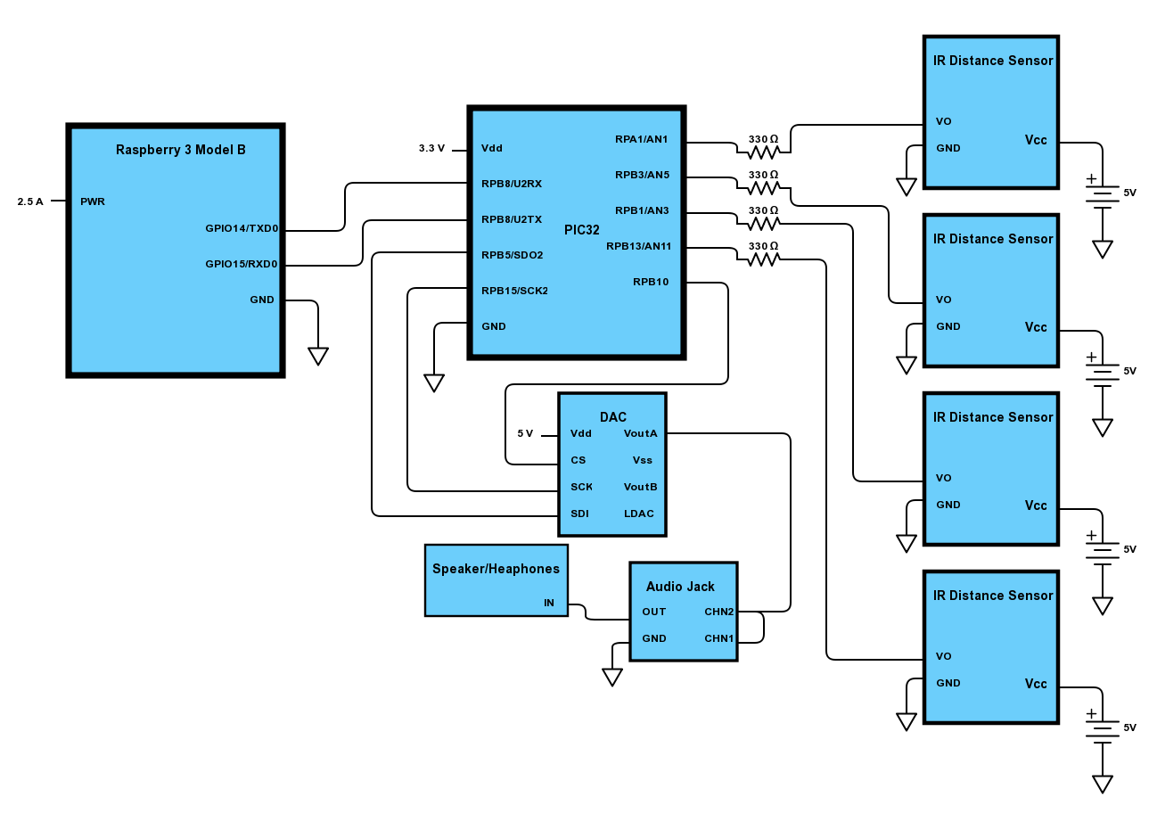
Figure 6: Schematic
D: Cost
| Part | Part # | Vendor | Total Cost |
|---|---|---|---|
| MicroStick 2 | N/A | ECE Lab | $1 |
| Big Board | N/A | ECELab | $10 |
| White Board | N/A | ECE Lab | $6 |
| PIC 32 Power Supply | N/A | ECE lab | $5 |
| PIC32MX250F128B | N/A | ECE Lab | $5 |
| 32GB Ultra microSDXC | SDSQUAR-064G-GN6MA | Amazon | $8 |
| Micro USB to USB | 701929 | Amazon | $4 |
| Lab Speakers | N/A | ECE Lab | $2 |
| 4 IR Distance Sensors | 136 | Pololu | $43.80 |
| Stereo Jack Connector | CP1-3543N-ND | DigiKey | $1.28 |
| $121.08 | |||
E: Task Distribution
Ben Francis: Wrote report, software design, soldering, circuit assembly
Jide Nwosu: Wrote report, software design, circuit assembly, consulting
Ayomi Sanni: Wrote report, sensor array assembly, software design, soldering
F: References
Data Sheets:
- PIC32MX250F128B Datasheet
- PIC32 hardware manual section Datasheets
- DAC Datasheet
- IR Distance Sensor Datasheet
- Raspberry Pi 3 Model B Datasheet
Vendor Sites:
Software:
- PIC32 Peripheral Libraries for MPLAB C32 Compiler
- Protothreads for PIC32
- Serial Communication Example