The Cell Phone Drone
By Tom Scavella (tbs47) and Ben Kocsis (bk285)

By Tom Scavella (tbs47) and Ben Kocsis (bk285)

We knew that this would be tough. There's a reason all of the drones you see on sale today have four motors, and that's because they're naturally much more stable than a drone with two motors and they're overall more fun and practical. However, quadcopters are still very unstable and could not be flown without some kind of flight contoller programming, which can give you an idea of just how unstable a dual-motor drone is. To make it work we would have to implement a PID (Proportional-Integral-Derivative) flight controller with servo-controlled motor mounts to adjust the pitch and roll of the drone. The details of the physical and software design can be found in their corresponding sections of this site. Information about the drone's position in space would be delivered to the Small Board via a Gyro/Accelerometer/Magnetometer chip, and then the servos would position the motors to the appropriate position to ideally maintain an "upright" position and remain stable.
After this was accomplished we would be able to mount a cell phone to the frame of our drone which, on a timer, could take photos or videos of the user without the need of another person to do it for you. We imagined someone being somewhere and they wanted a neat photo of some beautiful moment with themself and the Grand Canyon (or something) in the background.
Why didn't we make qUaDcOpTeR and simply attach a phone to it? Well, we were up for a challenge and our primary motivation/goal was to see if we could produce stable flight with a dual motor drone. We were well aware of the difficulties we would face along the way.
The drone was comprised of several componenets. As for the primary structure, there was the black frame and the white motor mounts which were fitted into the frame with thin metal dowels. The photos below are taken from our cadding software.


Assembling the drone was relatively easy. We used metal dowels to connect the motor mounts to the frame since they are strong and wouldn't break when we fired up the motors. A hole through each side of the frame and the mounts allowed us to insert the dowel. We needed the hole through the mounts to be bigger because we didn't want any friction hindering movement. The holes in the frame were very snug to prevent slippage and therefore held the mounts to the frame nicely.
We then had to attach the motors to the motor mounts. We came across a few issues. One was where the horizontal portion of our blade guard (the part that actually stops the blades from cutting you or other people) was too high and wouldn't cover the blades. The second being that the motors did not have any good way of being attached to the mounts because we failed to account for that in our modelling process. We killed two birds with one stone by screwing the motors onto thin pieces of wood which would then be attached to the mounts. The pieces of wood raised the height of the blades to be perfectly in line with the blade guard, and we could also epoxy the wood to the motor mounts. Problem solved.
Next we fitted the servos to each arm of the frame using industrial strength, double-sided tape. We shaped and fitted paperclips to each to attach the lever arm of the servo to the motor mount via a small hole drilled in one of the 'prongs' of the blade guard. This allows the servos to properly position the motors.
The battery was simply taped to the bottom of the frame with electrical tape. The speed controllers were taped to the backside of the frame. The Small Board and PIC32 were taped to the bottom of the front side of the drone. With everything in place, the drone was officially built.
The test rig was a great idea for our project as we would use it for essential calibration. While it wasn't an absolute necessity and we could have just placed the drone on the ground to test the flight controller, it prevented the drone from flying into our faces or into the cieling and causing unnecessary damage.
It was built out of some dingy 2x2 wood and it's design is fairly simple. The base is an 'H' shape which has two vertical arms coming up from the center of the base on each side. These arms had holes drilled into them of a diameter of 1/4 in (matching the dowel rod) which were slightly expanded using a rat tail file to decrease friction and allow for freer movement. This dowel rod goes through one arm of the rig, all the way through the drone, and out the other arm so that the drone can 'swing' back and forth.
We decided to start by diving into how to orient the drone. For this we used the Adafruit LSM9DS1 9-DOF Accel/Mag/Gyro Breakout Board. This board, described in more detail in the peripherals section, combines an accelerometer, magnetometer, and gyro all into one chip. It is a digital chip that communicates via I2C or SPI. The first design choice we had to make was which protocol to use. We decided on I2C for multiple reasons. For one, there was more information available online about I2C communication with the chip than SPI. However, the more important reason was that with I2C communication less wires were required for communication between the PIC32 and the LSM9DS1 chip. With this, all that is needed is a data line, clock line, ground, and power. This was not just because of the simplicity, but more because of our need to ensure we had enough I/O pins for use later with PID control of the servos and motors. We were going to be using the ECE 4760 ‘Small Board’ in order to reduce the weight and space that the big board would require. Because of this, we did not have a port expander and were fairly limited on the amount of I/O pins we had. However, even with the amount of resources online, we ran into a pretty substantial roadblock that would take up a lot of our allotted time for this project. We were not able to communicate with the board and the code we were using for communication was rewritten many times to try and fix the issue. However, it turned out that our issue was that the breadboard we were using was broken. When we could no longer think of what the issue was, we changed out the breadboard and we were able to communicate with the chip. Two weeks lost.
Finally able to communicate with the chip, we began working on the math that would be required to determine the drone’s orientation. We found a great article on the instructables website and used their method to get a fairly reliable position vector by combining accelerometer and gyroscope readouts. We started by getting the orientation with the accelerometer. The accelerometer works by measuring force, so knowing that gravity enacts a constant force on our chip and based on how much force was measured on each plane, we used basic trigonometry to calculate the tilt of each axis. However, even though this produced very reliable values when we were just holding the chip, it would not be sufficient when used on a drone. This is because besides gravity, the drone will experience other forces on it while in flight which would cause the force vector to not be pointing straight down as it would be if just gravity was acting on the chip. This is important because the direction the vector is pointing is where our drone would want to be perpendicular to, thus causing it to think it was level when it is in fact not. In order to fix this we cross-referenced the accelerometer data with previous position data to filter out noise and the gyro to make sure our drone was not trusting data from the accelerometer that was corrupted by outside forces other than gravity.
Gyro data is given in degrees per second or dps. This in itself is not a good measurement for finding position, as it doesn’t reflect what the position of the chip is, but rather if it is rotating or not. Fear not, for calculus had us covered! To get useful data from the accelerometer all we needed to do was reference the last known position and the time between readings. This is because we are able to “integrate” our rate of rotational change. We did this by adding the rate of rotation to the last known position, given by the gyro, multiplied by the time between readings. This then gave us an estimated position. We then used trigonometry to get into the same form as the accelerometer readings. Averaging these values, we got our final position that would be used for orientation.
Now the astute reader might notice that we now only have orientation for pitch and roll, but no yaw. Because the accelerometer just measures where gravity is we could not use this reading as a way of orienting our heading. In an ideal world we would have used the magnetometer for this measurement. However, due to time constraints and simplicity, we instead simply used the gyro in a similar way as above. But because there was no way to use the accelerometer as stated earlier, we did not have a way to check on the gyro and make sure it was not drifting. This is not something we were able to overcome and the chip’s idea of where the original heading was did slowly change. However, unlike orienting strait up and down, this was not as big of a deal because if the heading was slightly off, the drone would still be stable, which is not the case for making sure the drone is level. Regardless though, this method still proved to be really effective.
The next step was setting up the motors, speed controller (ESC), and receiver. Like with the LSM9DS1, more detail on the specific components will be provided below along with a circuit diagram. Basically, the battery would power the whole system as power was provided directly to the ESCs from the battery and each ESC had a Battery Elimination Circuit (or BEC) on board. The BEC converts some of the battery’s power to a 5v output that is fed to the receiver and the rest of the circuitry. Along with power, each ESC had a signal wire that would control the motor speed through a PWM signal sent along the wire. We only used one receiver’s 5v output to power everything, but used both signal wires since both motors needed to be controlled independently. We then went on to testing the motors with just the receiver and independent of the PIC32. We did this so that we could properly connect the motors to the ESCs. Since spinning a motor with a blade creates torque, one way to increase the stability of our drone was to make the two motors counter rotate, in that each spins in a different direction so that the torque created by each motor cancels the other out. This is something that can be seen on full scale dual rotor helicopters such as a chinook which doesn’t need a tail rotor for this reason. But back to our project... To achieve this we needed to play around with the wires connecting the ESCs to the motors, and through trial and error we figured out the proper configuration and then moved on to the next task.
We now had to get the PIC32 talking to the motors instead of the receiver. However, as an aside, for testing and safety reasons we decided to keep the receiver in the system in order for us to be able to kill the motors if things went wrong. Once we got all the stabilization working we planned on removing the receiver but we were ultimately unable to do this which will be discussed in the results section. Now back to getting the PIC32 talking to the motors. The plan here was to have the receiver input a throttle PWM signal to the PIC32 and then the PIC32 would reproduce the same PWM signal and send it to the ESCs to control the motors. This proved difficult and we tried a lot of different ways of reading the PWM signal input from the receiver. We first tried hooking up the signal to a filter and then an ADC input channel on the PIC32. However, we soon realized this was not going to work since radio control PWM signals have very small duty cycles and a fairly long period PWM signal around 22ms. Thus, we had to move on to plan B. This entailed using the PIC32 timer1 in gated mode so that when the input PWM signal went high, the timer would run and then we could read the timer and know what the duty cycle of the input signal was. But, alas this too did not work. We could not get anything to output, so we tried using both plib and directly manipulating registers, but we just were not able to do it. So it was on to Plan C. Thankfully, this worked! We decided to use the input capture peripheral of the PIC. We set this peripheral up to trigger on every edge and then kept track of which edge was triggering and took the capture time difference between the rising and falling edges. This time was then used to set the output PWM duty cycle and voilà! We were controlling the motors from our PIC32 based on throttle command from a transmitter that was connected to the receiver.
Next came the software. After getting all this set up we had to write all the PID control logic and create PWM output channels for talking to the servos. This was very similar to lab4 of ECE 4760, except instead of only controlling one axis, we had to control 3: roll, pitch, and yaw. The first thing we did was calibrate the gyro and accelerometer. To do this we took the position and gyro rate readings for the first five seconds after power is delivered to the board and then averaged these values to find our goal position and to get the error in the gyro readings. We would then use the averaged gyro readings to offset all future gyro readings, as the gyro would say there is a slight rotation even when the drone was completely still. This allowed for us to zero out the gyro readings so that they would be more accurate. We would use the averaged position readings as the goal position to be achieved for the PWM logic and the error would be calculated by how far off each axis is from each axis of the averaged position. Then we would update the servos according to corrections given for yaw and roll and then update the motors to account for corrections to pitch. In order to allow us to make sure the motors could be cut if needed, if the PWM signal from the receiver was below a certain value we would not input corrections to the motors, but instead keep them powered down. If the PWM signal from the receiver was above this threshold, then the update values would be added or subtracted from the PWM signal duty cycle being read and then sent out to the motors. In order to control yaw, the servos would move in opposite directions. To control roll they would move in the same direction. Finally to control pitch, one motor would speed up while the other slowed down so that there was unequal thrust along the roll axis perpendicular to the pitch axis.
We implemented this by using two interrupts and one thread. The first interrupt, which had the highest priority, was the one generated by timer2 and was called every 22ms as that was the period of our PWM output and timer2 was being used by all four output compare channels to generate the PWM output for the two servos and the two motors. In this interrupt, we computed base values as mentioned earlier and then after the calibration phase, the only thing that was done in said interrupt was setting the PWM duty cycle values based on corrections determined by PID calculations that were calculated elsewhere. The second interrupt was generated by input capture one and had a lower priority than the first interrupt discussed. This was where we read the PWM duty cycle of the receiver. Lastly we had a thread that was executed around every 25ms and was where we read the gyro and accelerometer values, calculated the orientation, and computed correction values based on tuned PID values. On top of this code we also had a library for reading the LSM9DS1 which was sourced from a Github repository online. However, as mentioned in our discussion for I2C communication, we modified this code when debugging the communication with the LSM9DS1. In the end, we ended up using the same helper method declarations, but rewriting the methods themselves to use the plib macros to control I2C rather than directly setting the registers as the code was originally written.
Before we could test we had stop using the big board and transition to a smaller board. Below, a circuit diagram can be found, but basically we used the small board and soldered it to a protoboard where we then soldered all the servo connectors and ECS connectors together. We originally had one of the ESCs providing power from its BEC to the board and all the components, however after the PIC32 kept resetting due to fluctuations in power from the ESC, we had to power the PIC separately with a 9 volt battery. The receiver and both servos were still sourcing power from the BEC.
After all this was set up it was time to calibrate the PID values. To help with this, we used our trusty test rig that would only allow one degree of freedom at a time so that the values could get really close to what they would be in free flight (without the risk of breaking the drone or hurting anybody). After this, we planned on fine-tuning the values in tethered flight before eventually letting the drone fly by itself. However, we were unable to accomplish this as will be discussed in the results section.

This peripheral uses I2c or SPI to communicate we chose to use I2c. There are pull up resistors on the breakout board so external pull up resistors are not needed. The breakout board also allows for the use of 5v or 3.3v input. There is a 3 axis gyroscope, 3 axis accelerometer, and a 3 axis magnetometer. All communication and desires by the PIC are communicated to the LSM9DS1 by writing to registers on the chip. This chip outputs a 6 byte chunk of data when being requested to output either gyro or accelerometer data. Where every two bytes are the lower and upper bytes of the x, y, and z axis respectively. These numbers are also in two's complement so we had to convert these values when doing calculations for orientation.
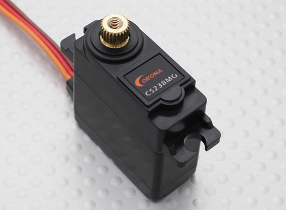
These servos take 5v input and PWM input where the duty cycle ranges from 1ms to 2ms and has a frequency of around 45Hz.

These speed controllers take in power from a battery or some other source and can handle 30 Amps of current. They have on board BECs that output 5 volts. They take a PWM input to control the motors that has a duty cycle that ranges from 1ms to 2ms and has a frequency of around 45Hz.
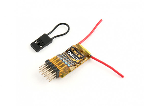
We originally did not want to include this component, but during tuning we wanted to have a way to cut the motors if need be. The receiver we used works with Spektrum radios and we used the Spektrum dx6i to communicate with the receiver. This receiver is a four channel receiver, however we only used the throttle channel as we just wanted to be able to control the motor speed. For each channel, this receiver outputs a PWM signal that, like our other components, has a duty cycle from 1ms to 2ms and has a frequency of around 45Hz as measured on an oscilloscope.
We sadly were not able to get our drone flying. This is due to two main bugs that we weren’t able to solve before our demo period. The first was that, randomly, an extremely large value would be read from the Gyro and accelerometer and would not clear. Sometimes, after such an event, the code would freeze and at other times it wouldn’t. However, even when the code kept running, the values would not be updated anymore which really confused us. This bug would cause the servos to max out and not move after that. Originally we thought this was a connection issue between the PIC and the LSM9DS1 because we were testing on a breadboard and the wires would pop out sometimes, but after we soldered everything together we still had the issue. One thing we could try in the future is using an analog Gyro and Accelerometer instead as maybe it was the I2C protocol acting up. But with this method we would be have to be careful of corrupting the data from the gyro and accelerometer with noise from the motors and ESC. The other bug we ran into was that occasionally, when the servos were correcting at a high rate, the receiver would loose connection and generally act in unpredictable ways. This was the main thing that stopped us from being able to tune our drone as when this would happen the motors would spool up unpredictably and sometimes just went straight to full power. This issue was most likely due to an bug in delivering power to the receiver as it only happened when the servos were under high load. Because of the nature of when this error would occur we didn’t realize it was happening until we started running, and at that point we didn’t have enough time to look into better circuitry to avoid this situation. Regardless, we are happy with how we were able to control the servos based on where the drone was positioned and definitely hope to get it flying outside of class. Until then, please enjoy the video below which demonstrates servo adjustment of motor position based on pitch, yaw, and roll.
As we've mentioned before, the blade guards are a literal life saver. Don't be the fool who is too lazy to cad some blade guards, because they just may save you from serious injury or even death (we're not kidding). Our project didn't interfere with any other groups' projects to our knowledge. This is likely because we didn't ever power up the motors in the lab, and the motors could cause a good bit of noise to nearby devices of other groups. Our trasmitter/controller used radio waves to communicate with the receiver, which could cause interference with other groups. In our case, nobody complained so we figured everything was fine. If you have two groups in the same room both using radio receivers, then the story may be a little different.
With regards to usability, there isn't much to say considering that we couldn't accomplish the drone's primary function of stable flight. What we can say is that our drone, and all drones in general, are dangerous. Our props spin at around 2500 RPM and have a radius of 2.5 inches. We'll save you the tangential velocity calculation and tell you that its REALLY fast and would cut through skin like a hot knife through butter. With that and our barely passable excuses for blade guards, our drone should not be operated by children or anyone without a decent knowledge of drones or the engineering behind its sporadic behaviors. Hopefully by the time the drone is perfected, its usability horizons will be greatly expanded to all.
At the end of the day, we were content with the physical design of our robot. It did not fall apart during testing and our blade guards actaully prevented an injury. In addition, the design of the drone did not hinder its performance or our ability to test it. The same goes for our trusty test rig. While it wasn't pretty, it worked perfectly and was balanced. This gave us one less thing to worry about during the horifying process of testing the drone.
With that being said, there were certainly some things we would change or suggest to others trying something similar. As our TA Ryan Hornung put it, "Measure twice and cut once" and we could not agree more. As mentioned before, testing and calibrating our drone required the use of a mounting rig with a dowel rod that goes all the way through the robot. If your holes on either side of the test rig and on either side of the drone are not at least almost perfectly in line, your testing/calibrations won't have mattered. We made the mistake of not measuring thoroughly and mostly just "eyeballing" it and that caused some issues necessitating redrilling more accurate holes.
Recall that there was a thin metal dowel connecting the motor mounts to the frame. It is in your best interest to design the pre-existing holes in your 3D model according to the diameter of metal dowels you have already purchased and not try to drill the holes after to fit the dowels. In our scenario, the dowels were snug in the frame, but too loose in the motor mounts. While everything held together, the motor mounts would 'jiggle' a good amount which is not ideal but also not catastrophic to the design.
Some other things we found very important... When testing the drone, ALWAYS ALWAYS ALWAYS make sure the rig is weighed down. We thought that the motors weren't strong enough to lift the whole rig. We were very wrong. Epoxy and double-sided tape were invaluable to our design. The epoxy was used to keep things together that absolutely had to stay together, such as the motor/wood unit to the motor mounts. Double-sided tape allowed for simple mounting of our various components to the drone, and they did not fall off despite the violent testing/calibration process. Blade guards are an absolute must. Drones are dangerous, and the one you're building yourself will definitley be magnitudes more dangerous. Blade guards may prevent serious injury (they did in our case). Finally, you should have a few extra motor mounts / blade guards printed. Depending on your design, these will probably be the thinnest and most fragile components of your drone and they will likely break at some point. We did not print extras, so we lost some time trying to fix broken motor mounts.
All though we didn’t get where we wanted to in terms of actually getting the drone flying, we were still pretty happy with what we learned. Due to the fact that we had such issues with the I2C protocol, we really had to dive deep into how I2C was working and into the data sheet for the LSM9DS1 in order to debug why this was occuring. In the end if it hadn’t been for a broken bread board we most likely would not have came away from this lab knowing as much as we do about I2C and about the LSM9DS1. We also learned a lesson in the building of complicated projects. For example, we assumed that the problem values we were receiving were a cause of a bad connection to the LSM9DS1, but in hindsight we should’ve realized this was not the case and kept testing on the big board before soldering everything to the small board. Once we did this we no longer had a way to print values which made debugging the issue much more challenging. Also these bugs that occurred later in the development of this project go to show how things aren’t always going to run smoothly and time should be planned accordingly to allow for unscene issues. For example, we couldn’t see there being any other issues once we started tuning and the issues we had with receiver power blindsided us. Lastly, we learned a lesson on feasibility of projects Professor Land warned us that this was an intensive project for a 5 week deadline, but we still decided to try and go for it. Even though it was fun, and we are very interested in stuff that flys, it was probably not the best decision as getting a flying drone is very difficult and if we were not able to achieve this goal there wasn’t much substance to fall back on in order to still have a somewhat working product. In all this lab and class was a great learning experience and I think we can both say we learned a lot and definitely hope to play around with microcontrollers in the future.
As we used an RF Transmitter, we had to ensure that our project abided by the FCC Part 15 rules, which we do as our transmitter is approved for sale in the US by the FCC.
The idea and foundation for our project is credited to Mark Rober who created a similar drone on his YouTube channel, and his video is linked in the references section of this page. No code or files of his were used in the making of our drone.
While making our drone, we were sure to follow the IEEE Code of Ethics and made our drone as safe as we were able. As has been stated numerous times throughout this page, DRONES ARE DANGEROUS and the one you are building yourself as a college student will definitely be magnitudes more so. Always make testing and usage of your drone as safe as reasonably possible. We found that it was best to not test our drone in public spaces such as in the lab and keep the danger away from others.
Below is a circuit diagram of our drone.

Below is a software flowchart illustrating how everything works together.
