Touch-Free Laser Piano
Caroline Chu (cc2295), Ashley He (ach238), Mira Kim (mk864)
Table of Contents
Rationale and Sources of Project Idea
Using the PIC32, we developed a touch-free, laser piano through the integration of a laser, mirror, stepper motor, and several light sensors. The user can play the piano by waving his or her hand across a streak of seven laser beams where each streak corresponds to a key on a piano. The laser piano is designed by attaching a mirror to a stepper motor and a laser beam is pointed at the rotating mirror. By manipulating the speed and direction of which the motor steps, we successfully produced seven laser streaks. The entire design is encompassed within a frame where the laser streaks are shot upwards toward their corresponding light sensor. If the light sensor is covered up and it senses no light, the piano key that corresponds to that light sensor will be produced. There might have been another way to approach the problem, such as having a light sensor on the motor itself instead of on the frame. However, we believed this was the optimal solution, given our limited resources and our knowledge about the microcontroller.
The rationale behind this project was that we were interested in developing an interdisciplinary product that combined our love for both technology and music. As we brainstormed ideas, the idea of creating a portable and low-cost piano surfaced. Pianos are one of the most commonly played instruments. However, they usually are on the more expensive side and are not very portable, even with electronic keyboards. Our touch-free piano would solve both these problems. It can be built with parts under $80 dollars and it can fit easily onto one’s desk.
Creating a portable piano was an interesting idea. However, our main source of inspiration of creating a piano that used lasers to display notes, came from our childhood. In elementary school, it was very common for the whole school to visit science museums. One of the more memorable science displays was the laser harp. It was fun, interactive, and easy to play for all ages. We wanted to apply the same concept to our musical instrument, but instead of making a harp, we wanted to make a more common instrument--the piano.
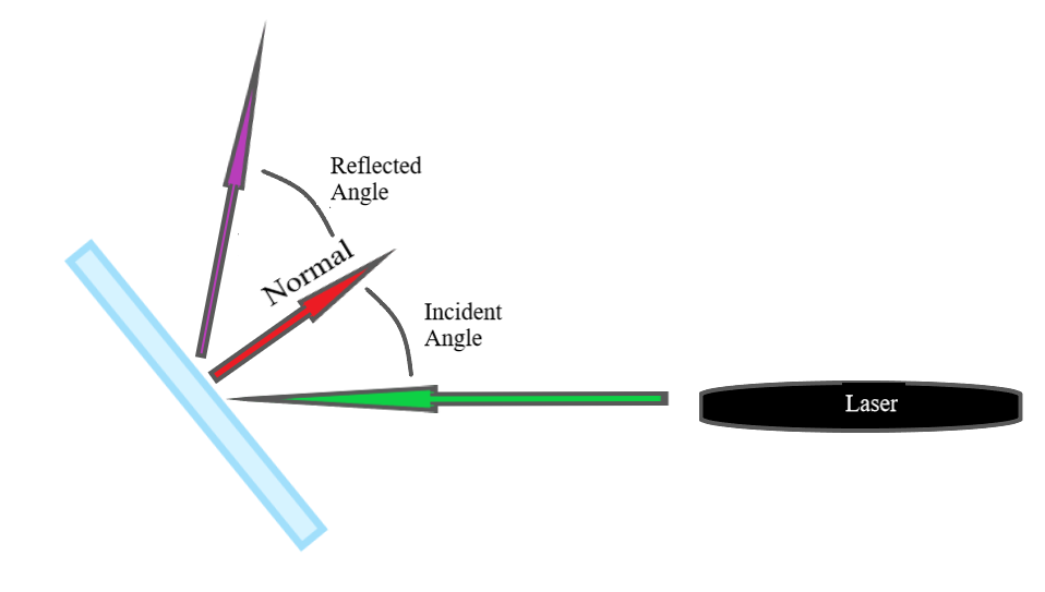
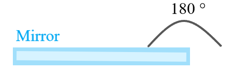
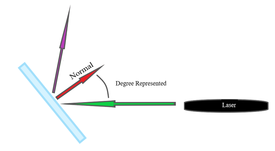
The main math behind this project was related to the interaction between the laser, mirror, and light sensor. When one shines a laser beam onto a mirror, there will be an incident angle and a reflected angle. Both these angles are relative to the normal of the mirror. In an ideal scenario when there is no loss of energy, the incident angle will equal the reflected angle. We used this assumption to make our calculations. Below is a diagram of the incident and reflected angle.
Constraints
Degree Range of the Mirror
|
Minimum Degree of the Mirror (not inclusive) |
Maximum Degree of the Mirror (not inclusive) |
|
|
|
Since it is known that the angle of the mirror range is 0° to 90°, we
divided the key degrees accordingly. We assigned the middle key to  = 45°. We then added 7.5° to each key above the middle key and subtracted 7.5° to
each key below. 7.5° is added and subtracted relative to the previous key’s degree. This is how
we got the numbers below. The degree below represents the degree between the horizon and the normal.
= 45°. We then added 7.5° to each key above the middle key and subtracted 7.5° to
each key below. 7.5° is added and subtracted relative to the previous key’s degree. This is how
we got the numbers below. The degree below represents the degree between the horizon and the normal.
|
Key corresponding to sensor |
F |
G |
A |
B |
C |
D |
E |
|
Degree relative to horizon |
67.5° |
60° |
52.5° |
45° |
37.5° |
30° |
22.5° |
To find the angle of the mirror, we used the equation below.

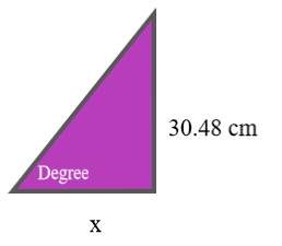
The last calculation we needed to make was to determine the distance of each light sensor from the mirror. There were 2 parameters we had, the degree relative to the horizon and the height of the frame (30.48cm). By using the trigonometric function, tan, we were able to calculate the distance needed. The given example below is for the key D.
Degree needed:
30 + 30 = 60°
tan(60°) = 
x = 17.6 cm
Therefore, the key D needs to be placed 17.6 cm to the right of the mirror. This calculation is performed for all the keys.
This project does not follow any of the IEEE standards. There are no copyrights associated with this system.
Our stepper motor rotated slower than expected in between steps, possibly because of interrupt service routine delaying the output signal to the stepper motor, so we had to put a software filter on the photoresistor readings to make sure the piano does not make sounds when none of the photoresistors are covered. Because the stepper motor was slow, there was too long of a time gap between when the stepper motor points at a photoresistor and when it points a beam at the next one. This made the system act like some of the photoresistors are covered when they are not. To fix this, we stored previous readings from each photoresistor into a buffer and OR-ed the previous seven readings with the current reading. Since each of the readbits are 1 when not covered (there is light pointing at the photoresistor), by OR-ing these bits, we are making it favor the “not covering” input over “covering.” For one photoresistor on the very end (the “E” note), we had it OR the previous nine readings and current reading since it was more prone to mistakenly registering as covered, since it is furthest away from the stepper motor and it has the longest time interval in between the laser pointing the photoresistor. This successfully solved the issue of piano generating sound when it shouldn’t, although this sacrifices response time when photoresistors are covered. Because the readings are OR-ed, when any of the readings are 1, the piano did not make any sound. Therefore, it takes more time for piano to start making sound once covered than it could with the photoresistor’s response time. This was a trade off for the functionality of the system.
The ISR is responsible for SPI communication for DAC. Because we are using the port expander and the port expander also needs SPI communication, it is important to wait for the port expander to finish its SPI transaction before writing DAC data. The DAC data is calculated by shifting the accumulated phase from phase increment from the photoresistor thread to the right 24 bits and then looking up this data in the sine table. 2048 is added to this data we want the range to be 0 to 4096. Although we do not to read the SPI for functionality, we need to read SPI because every time you write to SPI, you also need to read, and not reading here can confuse the next port expander transaction.
The timer thread updates every second to display the number of seconds since the program started on the TFT display.
Whenever port expander is being
used, it is important to put it in an SPI critical section to make sure it doesn’t get interrupted in
the middle by the ISR. The port expander is initialized and input pins are set up in the critical section,
and then the thread enters a while loop. In the while loop, each one of the input pins from the port
expander are read in an SPI critical section, and stored in variables. Then, each input goes through a
filter as mentioned earlier in the hardware / software trade off section. Next, the variable
‘playingnote’ counts how many notes are being played by counting how many photoresisters are
covered. If only one is being covered, the DAC frequency is set to play one note on the scale that
corresponds to its key. If two of them are covered, the DAC frequency is set to output dual tone of
corresponding keys. If there are more than two, the DAC outputs 0. The phase of the DAC data was
incremented by  . 25000 was selected since we want to
cover all ranges up to the highest note 1477Hz*16 (the highest frequency at a sample rate of 16 per cycle);
232 accounts one phase of the sine wave. This
increment variable is used in the ISR to calculate the DAC data.
. 25000 was selected since we want to
cover all ranges up to the highest note 1477Hz*16 (the highest frequency at a sample rate of 16 per cycle);
232 accounts one phase of the sine wave. This
increment variable is used in the ISR to calculate the DAC data.
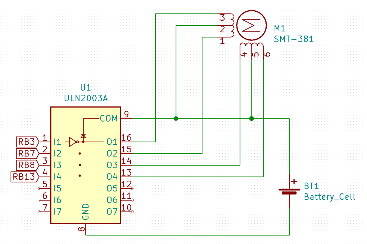
The stepper motor thread was used to control how many steps and to what degree the stepper motor would move at. Since we used a 6-wire stepper motor driven in unipolar mode, each time we set a bit to high and reset it back to zero, we could step through one step of 7.5 degrees. In unipolar mode, energizing the wires or ports in one order produces a rotation in either the clockwise or counterclockwise direction, and energizing the ports in the reverse order rotates the motor in the opposite direction. As depicted in the diagram in Figure 3.1, we wired the I/O ports RB3, RB7, RB8, and RB13 to the coils driving the stepper motor. To rotate the stepper motor one step in the clockwise direction, we first set RB3 high, yield the thread for 10 milliseconds, and set the bit low again. We then yield for another 20 milliseconds to allow the mirror to hold that position longer, to ensure there was a clear beam being projected onto the photoresistors. This process of setting and resetting the bit was repeated for RB7, RB8, and RB13 for two cycles for a total of seven steps in the clockwise direction. After that, the stepper motor would enter another loop where it would step seven times in the opposite (counterclockwise) direction. The stepper motor continuously stepped in a clockwise/ counterclockwise pattern as described above during the entire program execution.
In the main, timer is first set up at the rate of 1600 for 25ksamples/sec. Chip select and MOSI pins are configured for the DAC, as well as SPI channel set up. The sine lookup table is set up, and output pins for the stepper motor are set up. The TFT screen setup is done for printing time any useful information for debugging and the threads are set up and run in a while loop.
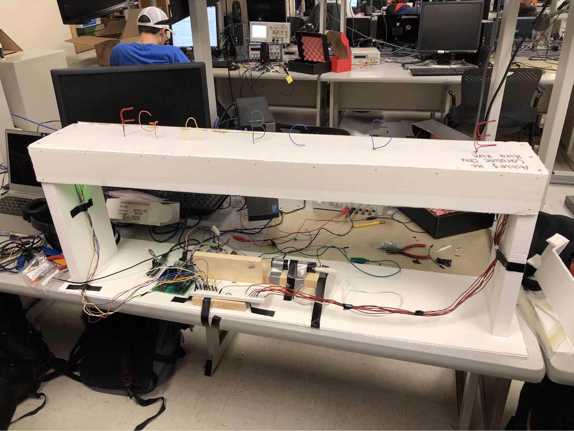
The piano needed a frame to hold everything in place, as alignment of the laser, mirror on the stepper motor, and the photoresistors are very important. To stay in the budget, we used foam board and styrofoam to build the outer frame of the piano. The length of the hood was decided by running the stepper motor and marking the shortest length with 7 different steps at an optimal height of 30.48cm. The stepper motor is screwed onto a piece of wood block, which is hot glued onto another piece of wood block where we taped the laser on. This whole chunk of wood was then taped onto the foam board. While this provided enough stability for our system, the system was still fragile to outer shock, so it would have been nice to get a more sturdy material or way of stabilizing our system to the foam board. Seven photoresistors were taped onto the hood, which has additional foam core covers pinned on each side to limit the amount of ambient light that reaches the photoresistors. Without these additions, the photoresistors did sometimes respond to other ambient light. Overall, we made the frame as sturdy as possible while trying to stay in the budget, which proved to be enough for stable functionality when there is no outside interference.
Figure 3.1: Stepper Motor and Surrounding Circuitry
To setup and control the 6-wire stepper motor, we first determined which wires corresponded to which coil that would drive the motor. We used a breadboard and plugged all six wires in an arbitrary order. We then used a multimeter to measure the resistance between the wires. If there was no reading on the multimeter, that indicated that the two wires being tested were not part of the same coil. For wires that were part of the same coil (three wires to a coil), the “center tap to coil end” resistance of that set is half of the “coil end to end resistance.” What we eventually deduced from that were that the red and black wires were the “center taps” of our stepper motor, and that the two coils were composed of the following combinations of wires: Coil 1 - Black, Grey, White; Coil 2 - Red, Purple, Brown. Next, we had to figure out which order to drive the wires to step the motor in the clockwise and counterclockwise direction. To do so, we attached the positive lead of a 5V power source to the center tap wires and the ground to the rightmost coil end wire on the breadboard (labeled as “4”). We observed the motor movement as we touched a wire connected to ground to the other three wires on the breadboard. If there was counterclockwise step, we labeled the wire “1.” If there was no step, we labeled the wire “2,” and if there was a clockwise step, we named the wire “3.” From there, we rearranged the wires so that it followed the order 1, 2, 3, 4. The colors that we found that corresponded to each of the numbers were as follows: White - 1, Brown - 2, Grey - 3, Purple - 4. Driving the wires in order from 4, 3, 2, 1, the stepper motor rotates in the clockwise direction. Driving them in the opposite order allowed us to rotate the motor in the counterclockwise direction. After that, we determined which I/O ports were available to use on the development board (RB3, RB7, RB8, and RB13). We connected the wires corresponding to 1, 2, 3, 4 to the ULN2003 IC driver (improved control for stepper motor) and then to RB3, RB7, RB8, and RB13 in that order. In the software, we can then control which wire is driven and at what interval.
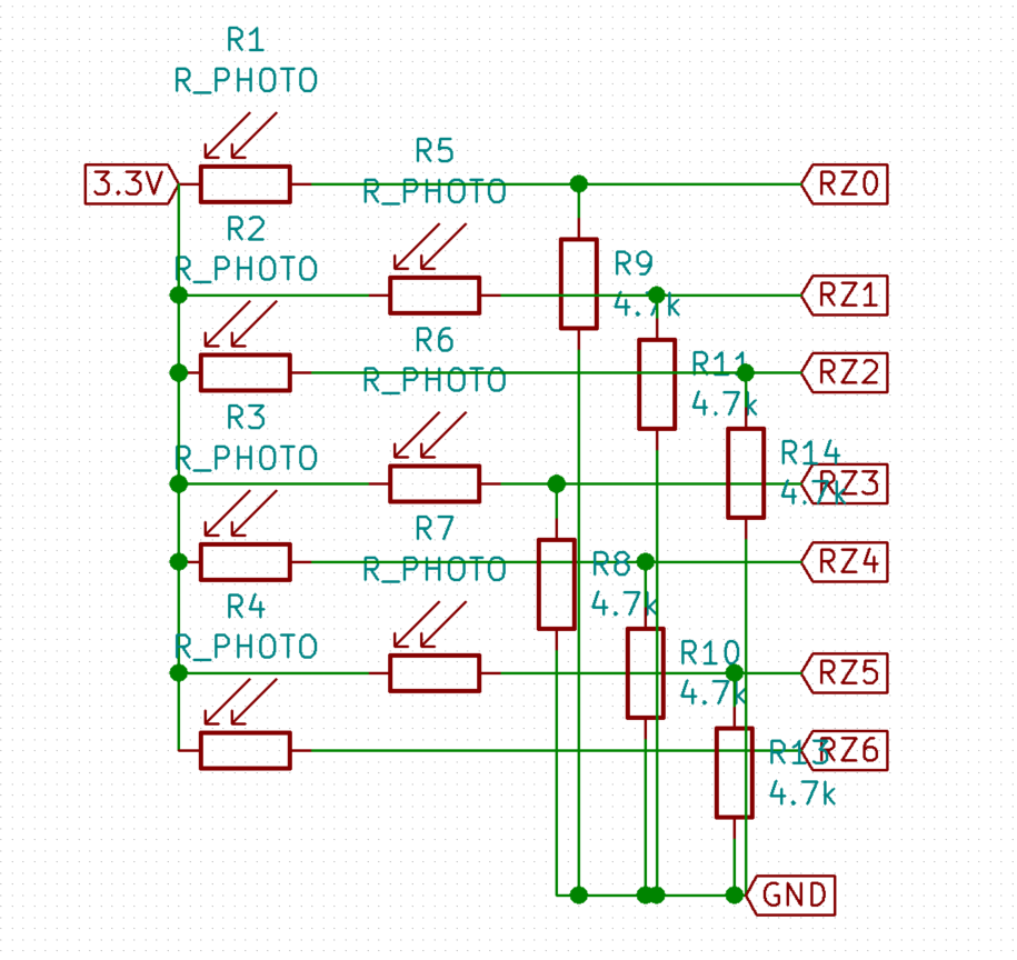
Figure 3.2: Photoresistors and Surrounding Circuitry
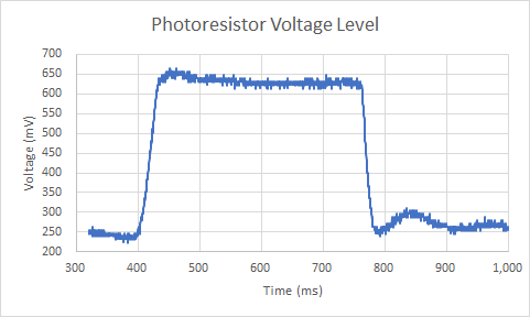
To make sure that the photoresistor response time is short enough for our system, we measured the photoresistor response time by reading the voltage from a voltage divider with a photoresistor to see how fast it takes for the photoresistor to change voltage levels. As seen in Figure 3.3, the response time of the photoresistor was fairly quick. It takes 54ms for the photoresistor voltage level to rise from 250 mV to 650mV. It takes 30ms for the voltage to fall back to 250mV. This data showed us that the photoresistors can respond fast enough for good response time of the overall system.
The photoresistors were set up as a resistor divider with 4.7kΩ resistors with 3.3V and GND from the PIC32 as shown in the schematics diagram, Figure 3.2. These are then connected to an input pin on the PIC32. When the photoresistor receives light, it reads 1 and when it doesn’t, it reads 0, as the photoresistor ranges from 120 - 1.5kΩ and the threshold for PIC32 to register as 0 or 1 is 1.8V.
Figure 3.3: The change of voltage level with a photoresistor resistor divider is shown.
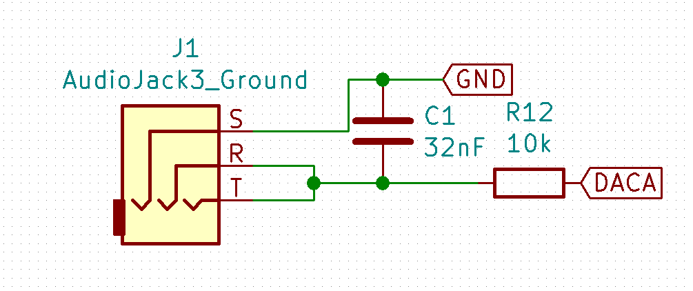
Figure 3.4: Audio Socket and Surrounding Circuitry
An audio socket is connected to DACA pin on the PIC32 through a low pass RC filter for noise filtering and audio output. A pair of lab speakers were plugged into this socket for audio. The schematics for the audio socket setup is shown in Figure 3.4.
Video Demo:
The system worked pretty well. The piano stays quiet when none of the photoresistors are covered, and when one is covered, it produces the sound that corresponds to its key after a little bit of delay. This delay is created from the software filtering mentioned above. The system sometimes acted a bit inconsistently and produced sounds when it wasn’t supposed to, as the photoresistors are very sensitive to change. Even hitting the hood of the piano a little can easily make the photoresistors unaligned from the beam, and make it act wrong. We didn’t fix the laser’s position on the wooden block in case we needed adjustments, but this created some instability. The best way to improve this would be to use a more stable material for the entire piano. Also, we noticed that the piano tends to act more inconsistently when it hasn’t been long since it was powered. Letting it sit for a while makes it more stable. Except for these stability issues, the piano worked well as expected.
Overall, we were pleased with the outcome of our project. The laser beam cutoff detection and sound generation worked well, and resulted in a very playable touch-free laser piano. The process of building this piano was extremely rewarding as it allowed us to apply our ECE knowledge gained from our undergraduate experience to create something that was fun, interactive, and related to our interest in music.
In this project, we learned the importance of being adaptable and how critical having properly functioning hardware is during the early stages of development. Originally, we planned on using MIDI for sound generation and only one photoresistor to track whether or not a laser beam was cut off and when. We found that the additional hardware and software involved in using MIDI sound generation would complicate our system greatly, so we decided to use DAC sound generation, which was something we were more familiar with. As for using only one photoresistor, after setting up the stepper motor and seeing the behavior of the laser beams, we discovered that it would be difficult to track which of the seven beams was being cut off with just the one photoresistor. We also found that having the laser beam unenclosed in the lab space was going to be a safety issue, and therefore needed to build a frame that would encase the beam and additional photoresistors to more easily track the keys played. In the end, the frame we built around our system made it more robust and easier to calibrate the beam detection and photoresistor placement.
Our beam detection for our system was not the most reliable, as there was a very narrow laser beam (about one millimeter) being reflected across the seven different photoresistors, and thus had a very small margin for error. Calibrating the system involved having to mount the laser and stepper motor combination to the frame, and then adjusting each individual photoresistor to coincide with the spots the beams shined the brightest on the top of the frame. Photoresistors that were placed closer to the mirror that reflected the laser beam had more consistent behavior when they were covered compared to the photoresistors closer to the edges of the frame where the beam did not shine as frequently or as consistently as towards the middle. Another problem we ran into was how precisely the photoresistors had to be covered to play a note; if there was any residual light bouncing off the frame from the laser, the note would not produce a sound or produce a sound at the wrong time. To combat some of the residual light interference created even when a beam was covered by our hands, we made a cup-like device to cover the photoresistor on three sides. This worked well, but still required precise movements from a user so not to interfere with beams shining on different photoresistors. This is something that can be improved in future iterations of the project by widening the laser beam (using a laser beam expander or a sheet of plastic) and decreasing the light interference seen by the photoresistors (could design a cover for each individual photoresistor that blocks ambient light).
Another small issue that arose was the speed at which the motor was rotating. We found that it was a bit slow in changing directions and stepping through the whole range, which resulted in some timing inconsistencies in creating the beams, despite setting the frequency to the correct value. This might be because we chose to drive the motor at 5V instead of 12V. For the future, it would be important to see if that change in power heavily impacted our motor’s function.
Standards
Our laser piano complies with aviation safety rules by always running the system indoors with an external hood/ frame, and never pointing the projected laser beams through windows.
Intellectual Property Considerations
Our laser piano is loosely based off of the laser harp linked in our references section (laser harp was patented by Bernard Szajner in 1981). However, our design differs substantially in how the sounds are generated and how we deal with tracking which notes are played. During the design process, we decided to use DAC sound generation rather than MIDI standard due to our previous experience and to improve our system’s portability. We also added a frame for our system to contain our laser beam. We consider our use of a frame an improvement as we can more easily and reliably control the beam and photoresistor placement for a more accurate read of what notes are played. Another major difference in our project is that we allow for multiple notes (up to two) to be played simultaneously, and we chose to not play any sounds for any number of notes exceeding two.
All of our source code in lab5.c was written by members of our group. Libraries that we used such as the protothreads and port expander libraries were used with permission of the instructor, Bruce Land. Our code is open-source and can be published in any magazine or journal. No design was reverse-engineered to create this project. We had no patent or trademark issues. No non-disclosure agreements were signed. There are no patent opportunities for this project.
Ethical Considerations
Since we were using a relatively high power laser in combination with the unpredictable nature of a rotating mirror, we had to take constant precautions in building and testing our system. We never left the laser on while we weren’t actively testing or monitoring the system and we tested the mirror/motor movement without shining the laser on it whenever possible. Additionally, we used a black bag as a shield around the laser beams to prevent the beams from shining across the room, and ultimately designed a frame for our system to contain any beams generated through the mirror’s reflection. We did most of our testing in the back corner to also minimized any interaction with other groups and we also operated the laser far from eye level, which is compliant with the requirements of the IEEE Code of Ethics with regards to holding “paramount the safety, health, and welfare of the public.” Finally, by making our code, schematics, and design process open source and available to the public, we hope to encourage understanding of technology, its capabilities, and societal implications as per point five of the IEEE Code of Ethics.
The group approves this report for inclusion on the course website. The group approves the video for inclusion on the course youtube channel.
|
/* |
Figure C.1: Audio Socket and Surrounding Circuitry. DACA and GND are from PIC32
Figure C.2: Photoresistors and Surrounding Circuitry. 3.3V and GND are from PIC32
Figure C.3: Stepper Motor and Surrounding Circuitry. 5V power supply from lab is replaced with a battery.
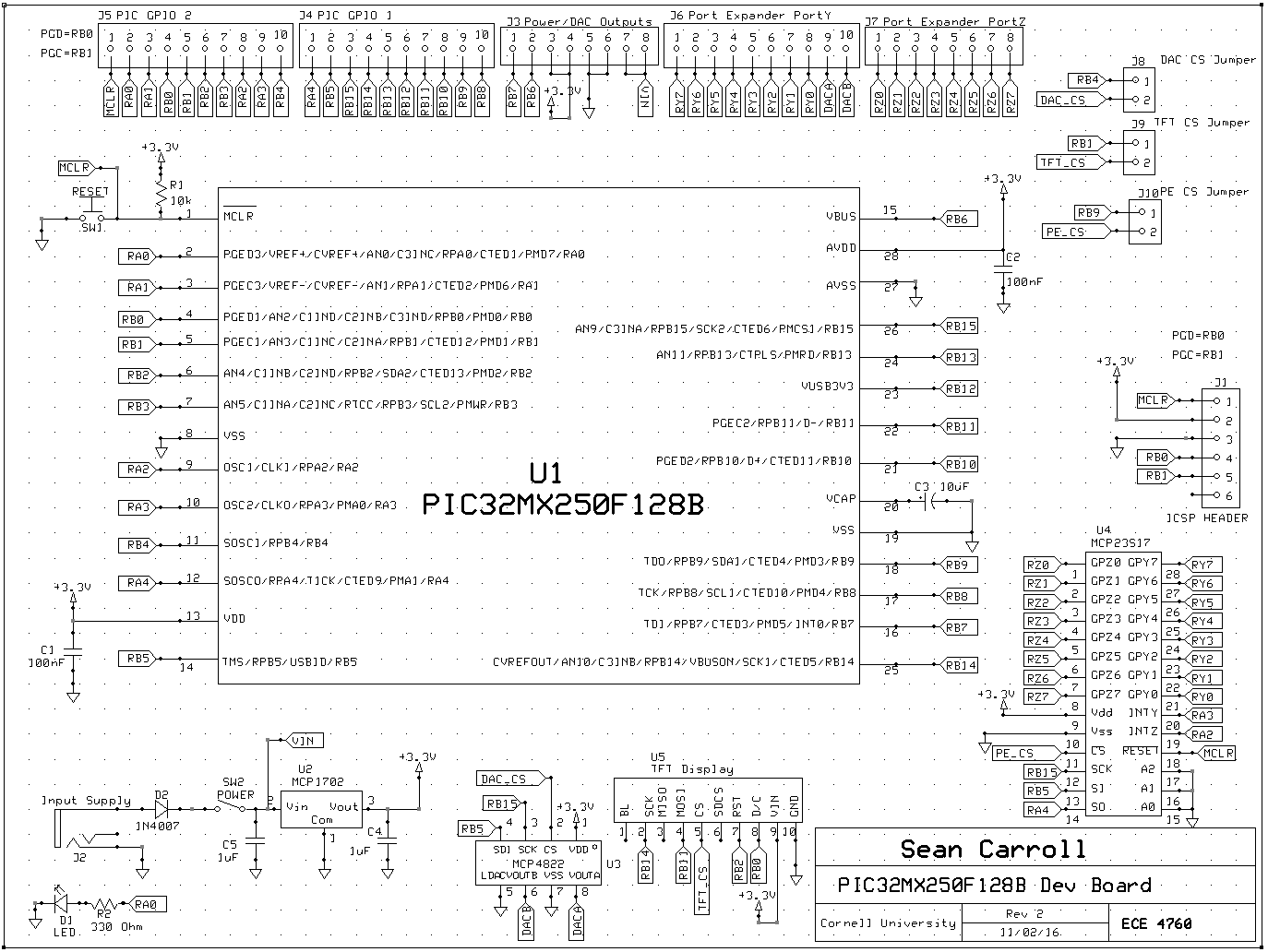
Figure C.4: PIC32 Large Dev Board Circuitry
Source: http://people.ece.cornell.edu/land/courses/ece4760/PIC32/Target_board/Large_board_sch_image.PNG
|
Part |
Quantity |
Cost and Vendor |
Vendor |
|
Stepper Motor |
1 |
$2.25 |
All Electronics |
|
ULN2003 |
1 |
$0.75 |
All Electronics |
|
Light Dependent Resistors |
7 |
$6.65 |
All Electronics |
|
Green/Blue Laser Safety Goggles |
1 |
$10.99 |
Amazon |
|
Small Mirror |
1 |
$0.25 |
Amazon |
|
Green Laser Pointer |
1 |
$18.17 |
Amazon |
|
Foam Core Board |
1 |
$0.00 |
Phillips Lab |
|
1-inch thick Styrofoam Board |
2 |
$0.00 |
Phillips Hall Recycling Bin |
|
4.7KΩ Resistors |
7 |
$0.00 |
Phillips Lab |
|
Jumper Cables |
18 |
$1.80 |
Phillips Lab |
|
Breadboard |
2 |
$12.00 |
Phillips Lab |
|
Power Supply |
1 |
$5.00 |
Phillips Lab |
|
Lab Speakers |
1 |
$2.00 |
Phillips Lab |
|
PIC32 Large Dev. Board |
1 |
$10.00 |
Phillips Lab |
|
MicroStickII |
1 |
$1.00 |
Phillips Lab |
|
PIC32MX250F128B |
1 |
$5.00 |
Phillips Lab |
|
Total: |
$75.86 |
||
|
Caroline |
Ashley |
Mira |
|
|
|