IOT Home Automation
By Kevin Ying, Anthony Viego
For our ECE4760 final project we built a wireless star network with the PIC32 for remote monitoring and automation. Meant to augment users' abilities to gain insight into their homes through a monitoring station, our system is designed around reliable communication between individual low-cost nodes communicating at 2.4GHz which can be easily added or removed.
Over the past few years the world has seen the rise of “IoT” devices. But what is IoT and how can it be useful? IoT itself is a broad term and can refer to any modern device that has the ability to transmit data wirelessly. While companies and manufacturers are probably the largest users of IoT devices currently, these sort of devices are starting to become prevalent in homes as well. However, while this is true, no device so far has been made that tie all of these devices together. Instead, a separate app or some other sort of controller is required for each device. Our project aims to rectify this situation by creating a hub in which all IoT devices in the home can communicate and send data. This will eventually allow for the creation of the “smart home” in which everything in the home such as the thermostat, lights, and even the doors can be controlled automatically or wirelessly.
This project was inspired in part by Kevin's co-op with the home and business automation company, Alarm.com, which provides home security as well as integration with dozens of hardware partners unified into a single web and app experience.
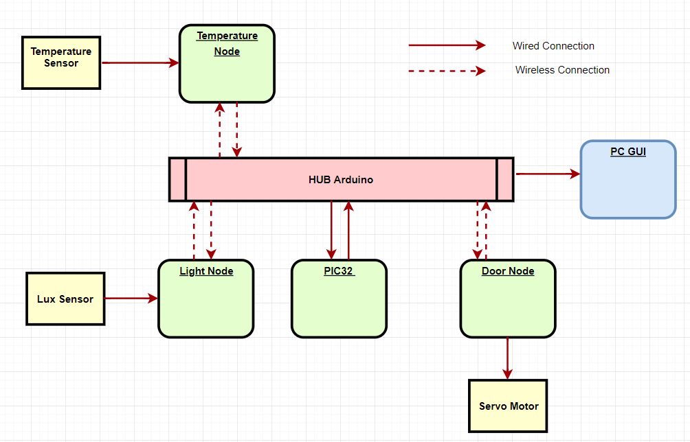
Our wireless star network can be divided into 6 main components(see figure 1). The center of the star in the case is the hub arduino and PIC32 that it communicates with. The PIC32 is considered to be the brains of our network and is responsible for handling the data transmitted by each node on the network. Our network structure overall is fairly simple. The PIC32 will send a message requesting data or some action by a node to the hub arduino using UART serial communication. The hub arduino will then read in this message and broadcast it to every node on the network using an nrf2401+ radio.
Each node on the network will receive this message on their own radios and use data parsing to determine if the message was meant for them. If a node has determined that message was not meant for them then they will ignore the broadcast and continue listening for new transmissions. If the message was meant for them then the node will process the rest of the message and determine what action to take. This design decision was made to reduce noise on the network and prevent missed messages due to network spam.
As an example of an action, the PIC32 might ask the light node to send data on the current level of light the lux sensor is reading. Upon receiving the transmission the light sensor will then broadcast this data across the network. Once again each node will receive this info but only the hub arduino will actually act on the information which in this case simply involves sending the info back to the PIC32 and the PC GUI through UART communication. Finally, the PIC32 will process this information and display it. The PC GUI will also perform a similar function and acts as a secondary display in the event that a TFT is not available for use with the PIC32.
Figure 1: Block Diagram of Overall Connections
One of the design decisions we made when working on this project was to use Arduino Nanos to interface over SPI with each nrf2401+ radio module. As a result of this we needed to implement UART communication from the HUB arduino to the PIC32 which added a fair bit of additional complexity to the software design. However, we felt this choice was necessary as our attempts to make the radios communicate properly using PIC32s proved much more challenging than anticipated and ultimately failed after having spent many hours.
Specifically, the following libraries were attempted to no avail. Sometimes, individual messages would be send and received immediately after reset, but our team found it impossible to use the following libraries reliably.
- Douglas Katz and Fred Kummer's PIC32 library
- Andrew Kessler's Northeastern University PIC32 example code
- maniacbug RF24 library, converted for use with the PIC32
- Simon Barker's PIC18 libraries, converted for use with the PIC32
We ultimately settled up the Nano solution, utilizing an optimized RF24 library found here.
Hardware Design
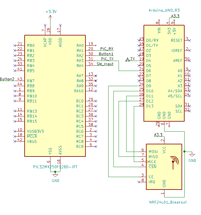
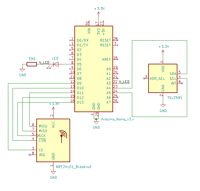
The hardware design consisted of a few main components. As seen in figures 11-15 of appendix B, our hardware design consists of four arduinos one of which is connected to the PIC32 microcontroller. The arduino and PIC32 are connected via 2 wires, one RX and one TX wire for UART communication. In addition to that the grounds of the arduino and PIC32 are also connected to create a common ground which is essential for ensuring stable communication. Each arduino is connected to an nrf2401+ radio module via 7 wires which allow for power, ground, and SPI communication between the devices.
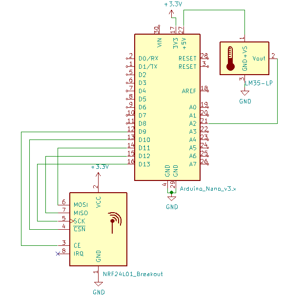
Each node also has additional hardware. For the temperature node this additional hardware consists of a small analog sensor which is supplied power, ground, and a third wire which connects to pin 3 of the arduino.
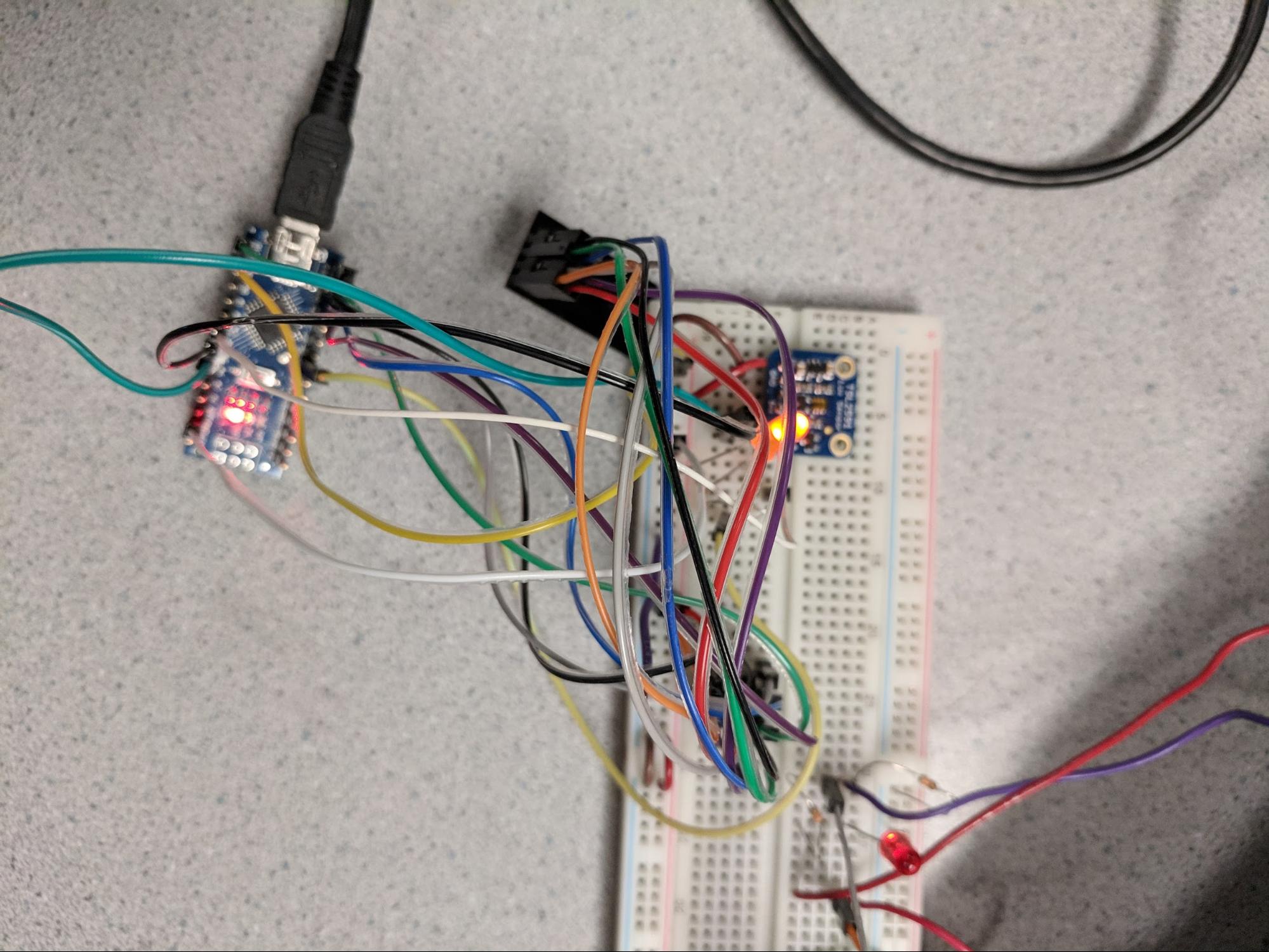
The light node has an additional lux sensor which is used to measure the light level of the room. The sensor uses the I2C protocol for communication.
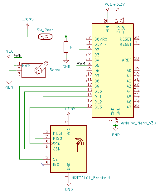
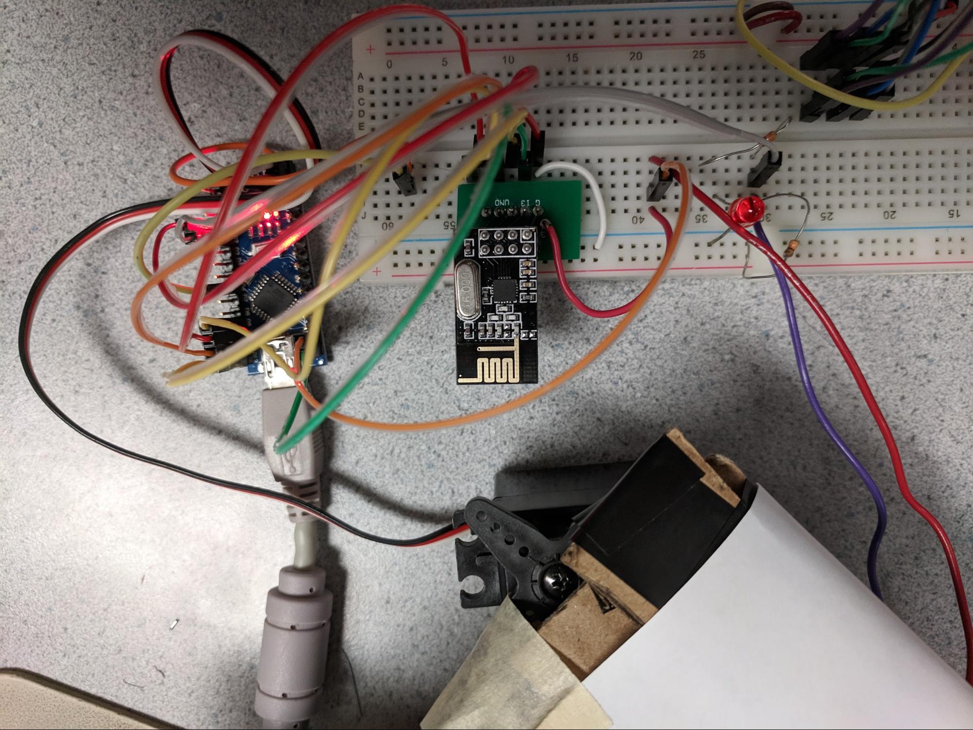
The door node has an additional servo motor and magnetic sensor which are used for opening and closing a door. For the magnetic sensor, when the two halves of the sensor are brought together the internal connection shorts and power flows across the wire. When the halves are seperated the connection is not made, and the other half of the wire floats. Thus when the door is closed power with flow through the wires, and when it is open it will not. The servo itself is operated used a PWM signal from the arduino.
For schematics of the final design, see Appendix B.
Our code for the PIC32 makes heavy use of the PIC peripheral libraries, as well as the Protothreads framework for lightweight cooperative thread scheduling. The code on the PIC32 can be separated into five major parts: UART communication, data parsing, the display protothread, the switch reading protothread, and initialization. All code for the PIC32 was written in C.
This thread controls the bulk of the processing on the PIC32. It handles spawning the threads in pt_cornell_1_2_3.h which handle sending and receiving data over UART, calling DataParse() to parse received data, reading in the two button inputs, and writing to the TFT display.
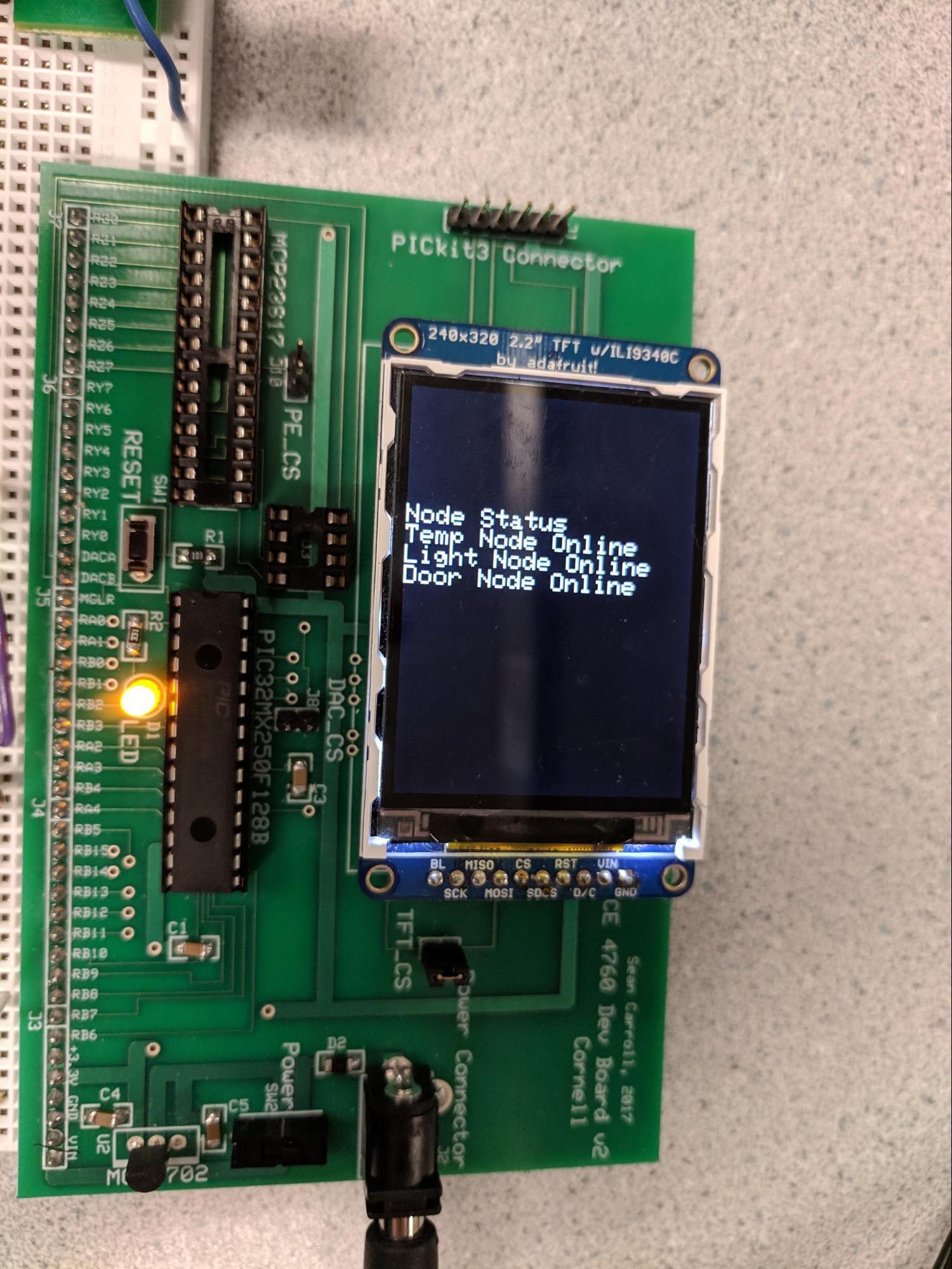
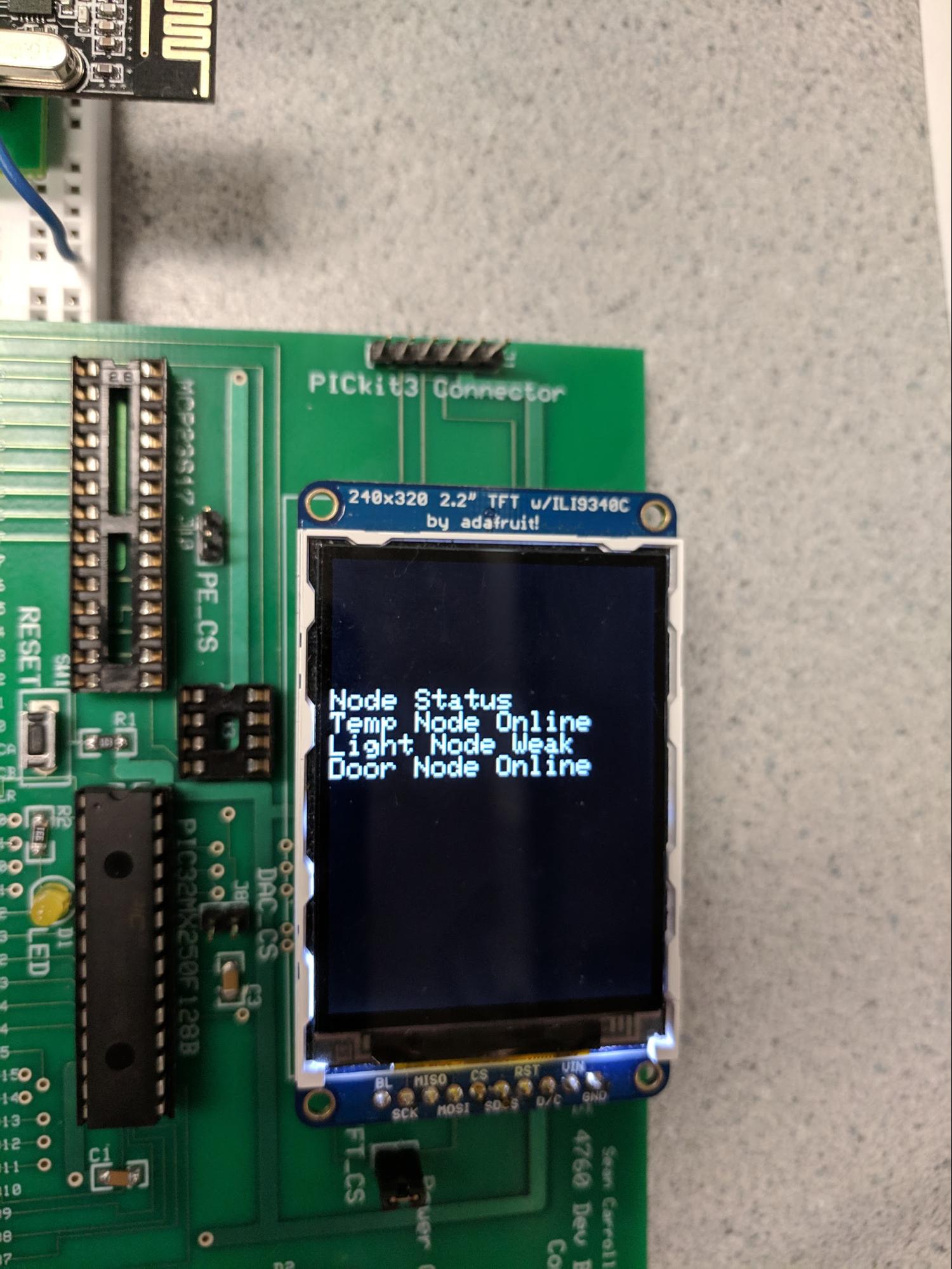
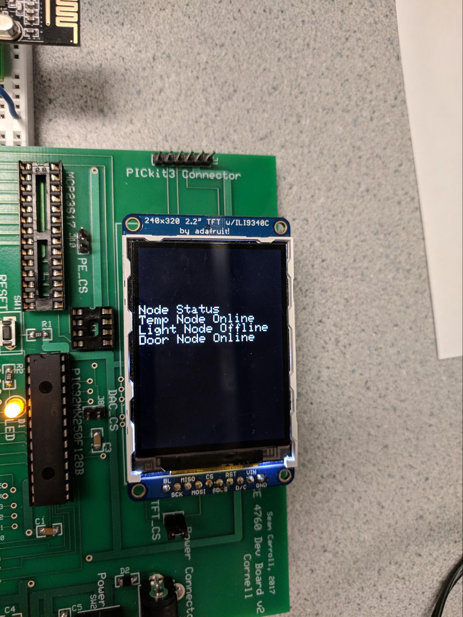
This thread has four display modes which affect what is written to the TFT and what message is written to UART to be send over the radio. In the first, the status of each node is written to the TFT, based on the number of attempted transmissions since the last received message from that node. The written status can either be Online if a message was recently received, Offline if not messages have been received after 10+ attempts, and Weak for intermediate numbers of attempts. A counter keeps track of the number of attempts, and the node which is contacted changes after 5 failed attempts, in order to more quickly cycle through each node. Based on which node it is currently trying to contact, a send buffer is written to with different messages.
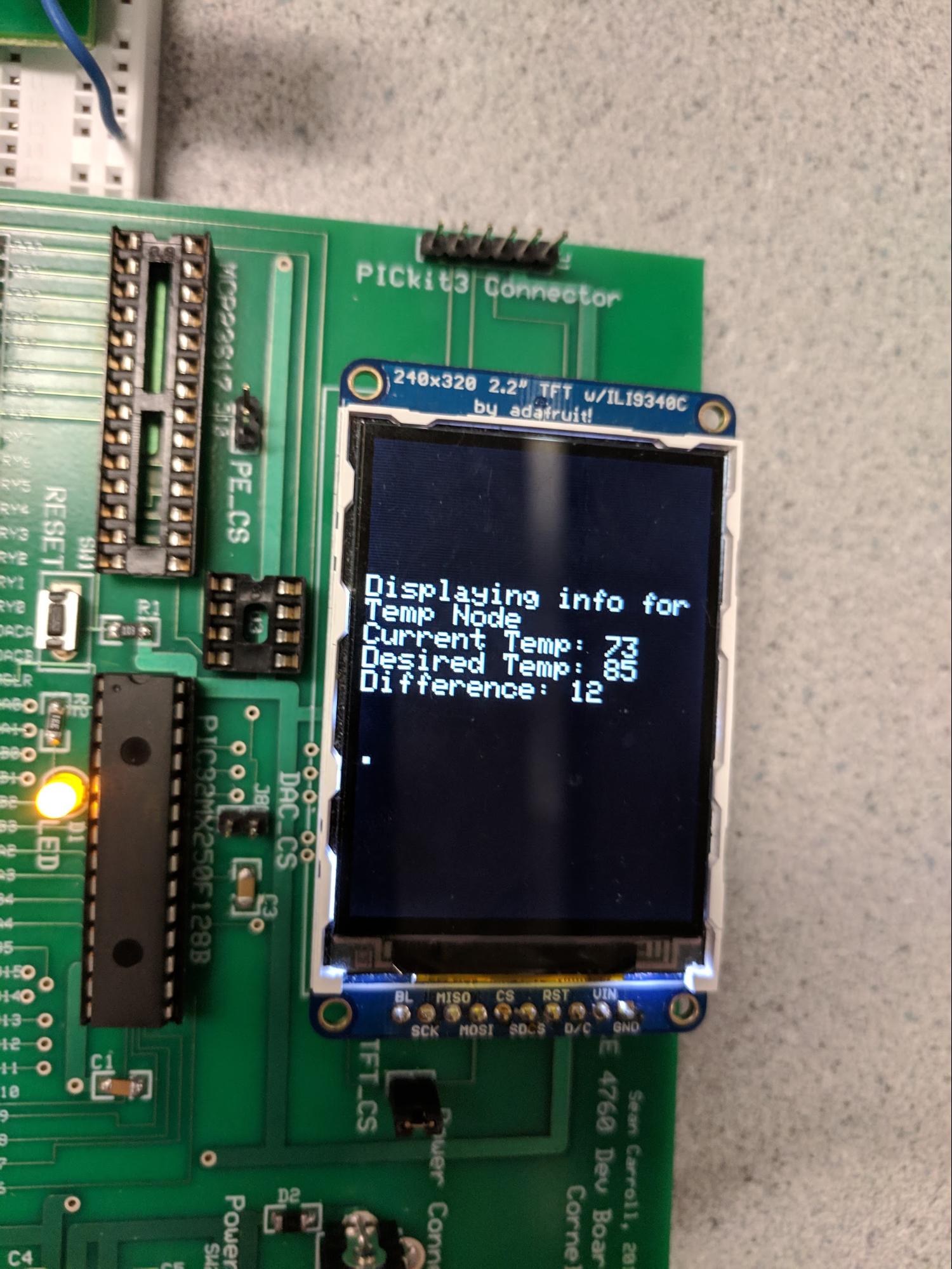
In the second mode, the PIC is focused on the temperature node. It displays the most recent temperature reading, a desired temperature variable which is changed on the press of button 1, and the difference between the two. Button 2 controls whether the temperature node is polled for readings, or if the current desired temperature is sent as a message to the temperature node to be set.
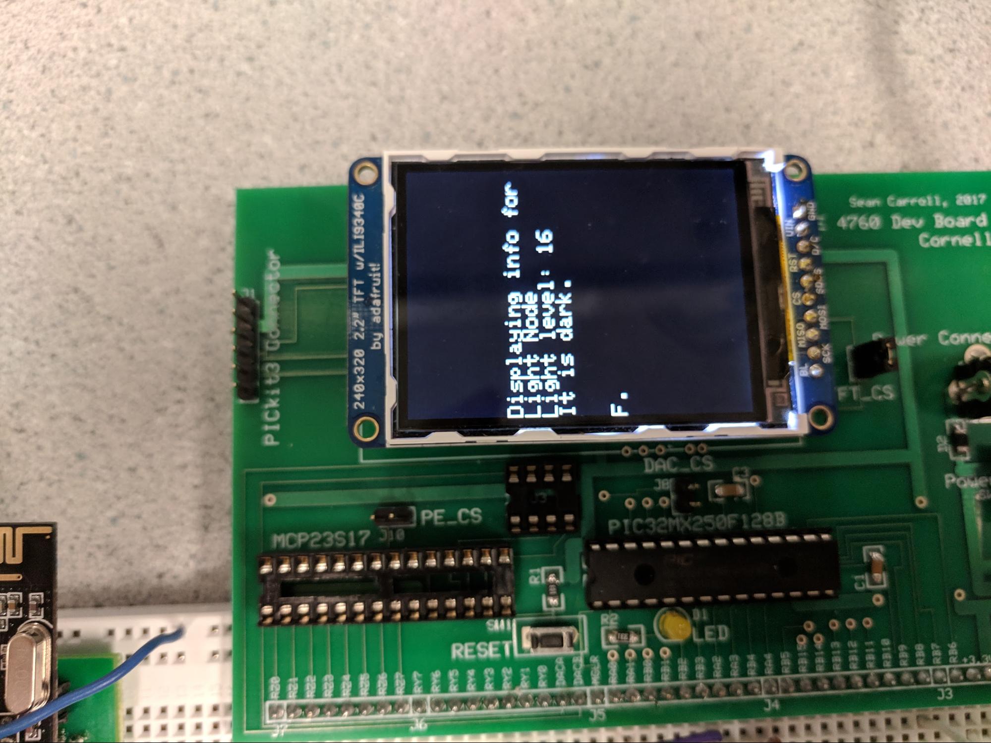
In the third mode, the PIC is focused on the light node. It displays the most recently received light level reading, which is then translated into whether the light sensor currently believes the room is fairly dark, or bright. A threshold was chosen such that most indoor environments will be shown as dark, while those outside or in direct sunlight will be labeled as bright.
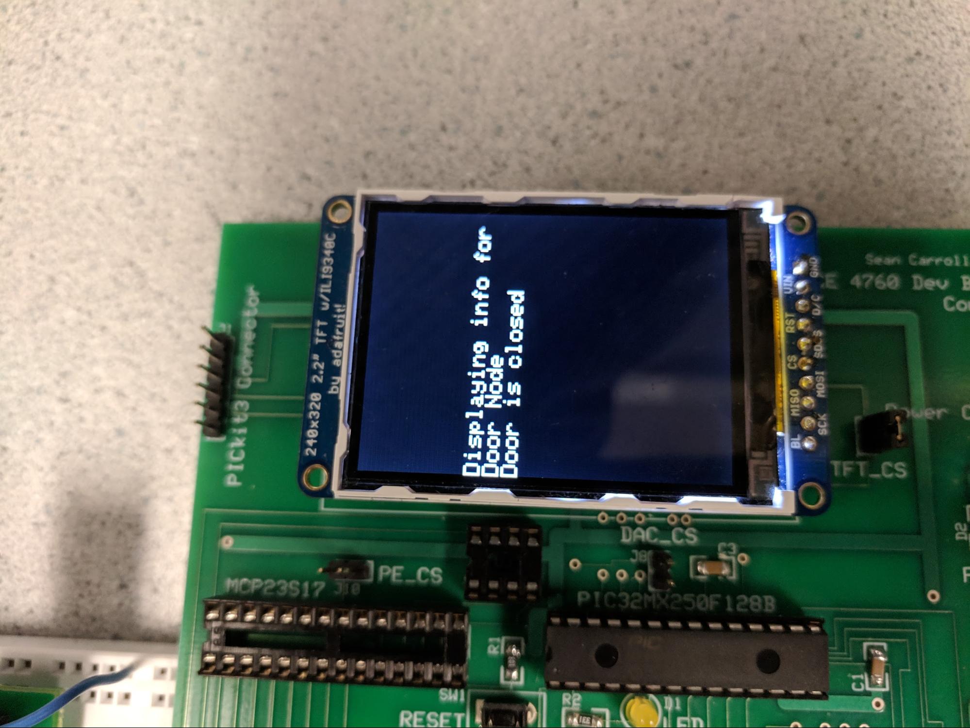
In the last mode, the PIC is focused on the door node. It displays whether the most recently received door node message indicated that the door was open or closed. Pressing button 2 sent a command to the door node: the door should open if button 1 was also pressed, and close otherwise.
Data parse searches the buffer in which data received from UART is written to, checking for colon placement and using the received message to determine the origin of the message. If a valid message is received, the relevant data fields are then updated to be used in protothread_update(), and the corresponding node is marked as having recently connected.
For more details about the message format, see below.
This thread reads in the switch digital input, which increments which display mode the TFT is currently.
A header file containing configuration parameters for the PIC32 provided by course instructor Bruce Land. The baud rate was changed to the required 9600 bit/s
A header file containing a PIC32 compatible implementation of protothreads provided by course instructor Bruce Land. PT_GetMachineBuffer was edited to clear UART errors. Note that there are several other edits to this file, although those should not affect functionality. These edits were in an attempt to be able to include this header file from multiple other files, since pt_cornell_1_2_3.h initializes some of its global variables on declaration. However, C does not allow such behavior, even if hidden inside of #ifndef directives.
A rewrite of the Adafruit TFT library, mostly for the simple graphics functions. Provided by course instructor Bruce Land
A rewrite of the Adafruit TFT library, containing mostly more advanced functions such as circles and triangles. Provided by course instructor Bruce Land
To communicate between our hub arduino and the PIC32 we chose to use UART since it is a simple and relatively reliable 2 wire communication system. On the PIC32 side we used the hardware UART2 while choosing to use the Software Serial library on the Arduino side (see Appendix B). This library allowed us to have UART communications while using the non-standard UART pins on the arduino. This allowed us to both communicate with the PIC and have a separate debug output to a computer display, as well as remove the need to unplug the wire connecting to the Arduino’s RX pin everytime we wished to reprogram to Arduino, since Arduinos program over the serial pins.
Something important to note on the PIC32 side is that for our specific variant there is a major flaw in the RX buffer. This flaw is documented in the errata and states that if the RX buffer overflows then the UART will become unsynchronized effectively breaking the UART until it becomes synchronized again. To avoid this we made sure to constantly clear all errors resulting from the UART and decreased our baud rate to 1200 to ensure we were reading the data from the buffer quickly enough. This is reflected in the edit to the UART reading implementation found in pt_cornell_1_2_3.h.
To help increase the reliability of our UART communication we also added in framing for our data. We chose to add an ‘@’ and a ‘#’ character before and after every message sent respectively. This allowed the receiving device to determine when to begin and end reading a message. While a single end character did work we found that we were able to drastically reduce the number of incorrect messages by also adding a start character. Furthermore, as mentioned we chose to reduce the baud rate of our communication to further increase reliability as we were seeing a large number of framing errors when the PIC32 was receiving data at 9600 baud.
Each of our nodes were designed to communicate wirelessly. To accomplish this they each made use of the nrf2401+ 2.4Ghz radio. The Arduinos used SPI (Serial Peripheral Interface) to communicate with each radio. To increase reliability in our wireless communication we initialized each radio to use a payload size of 12 bytes (rather than the original 32) and also configured each to use the minimal power setting since we were using the radios at a close distance.
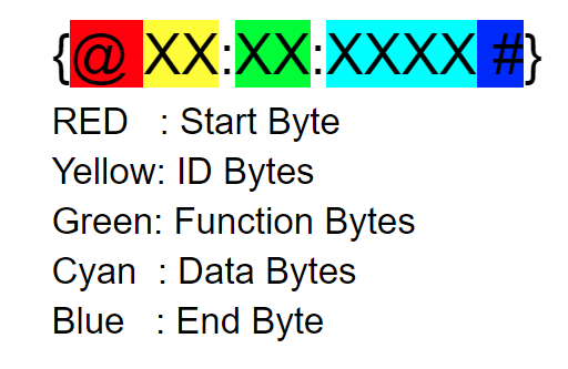
When designing our network we decided to standardize the messages being sent. One of the main reasons for this is that we wanted a standardardized message length which allowed us to minimize our payload size to help improve reliability. Furthemore, by standardizing our message encodings we were able to quickly develop parsers for each node which were used for determining the type of message and the requested action. Also, this allowed our PIC32 to easily determine which node the message came from and what kind of data it was. This means that our network has a factor of expandability since as we continue to add more nodes to the network each node will have its own unique ID. Based on our case-sensitive message encoding format(see figure 2) we could have a total of 1352 unique devices with over 450,000 functions per device. Note that most devices would never need close to that many but the possibility is there. The way the encoding works is simple but effective. As mentioned the first two bytes store the unique ID of each node. This is used to determine which node is meant to receive a message. Following this is a colon to help with parsing and error checking. The function bytes can then be seen in green. Typically these are used to tell the node if it should be expecting to send data or receive it. Finally, in the cyan bytes will be data for processing and action.
Figure 2: UART Payload Encoding
The arduino connected to the PIC32 acts as the networks hub, relaying information back and forth from the wireless network to the PIC and vice versa. To accomplish this the arduino makes use of the RF24 arduino library and the Software serial library as mentioned. The code of the arduino is designed in such a way that it will first expect a message from the PIC32 on the software serial lines, and will wait accordingly. Once a message has been received it will then handle the message based on the start and end bytes. Once the message has been properly received it will broadcast this message to the network and then wait for a response. To avoid an infinite while loop in the event that the destination node misses the message, we added a timeout function which will cause the hub to exit the loop and wait for the PIC to send a new message to be transmitted. In the event that a message is properly received from a node, the arduino will then send this information back to both the PIC32 via software serial and the GUI via the built in USB connector. It should be noted that the data sent to the GUI and the data sent to the PIC32 is the same minus the bytes used for framing. The differences in the bytes used for framing are simply a coding choice to differentiate between the two receiving devices.
In the process of designing this code we ran into a few issues. One of the major issues we saw was data being sent from the UART to the arduino becoming unsychnozied and resulting in messages the nodes on the network didn’t know how to handle. Shortening the length of our wires from the arduino to the PIC32 seemed to help rectify this issue which lead us to believe there was a significant amount of noise interfering in the original setup.. Additionally, the use of start and end bytes also helped to fix this issue. While testing our individual nodes we also ran into the issue of some of our nodes messages not being received by the hub. Through some experimentation we realized this issue was due to a “spamming” of the network itself by other nodes which was caused by the hub sending out multiple messages across the network at once. Adding the wait after sending data as mentioned above helped to resolve this issue.
In general each of the nodes functions similarly with the key differences being the functions unique to each. Overall, the nodes each start by waiting to receive a message via the wireless network. Once data has been detected within the rx buffer of the radio, the message is read in and stored into a buffer on the arduino. Once stored the node then parses the data to determine if the message was meant for it by comparing its own ID to the ID stored in the first two bytes of the message. If the IDs match then a handling function is called which varies for each node. For debugging purposes the received message and the message eventually broadcasted are written to the serial monitor to ensure correct functionality. Each node determines which function is being requested of it by parsing the 2 and 3rd set of bytes in the message and comparing the results to known function types.
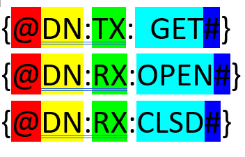
Figure 3: The Get Door State, Open Door, and Close Door Commands
The door node serves as an example of how the network can be used to open and close doors. The door node is equipped with three functionalities, status, open, and close. When the status message is received by the door node, it responds with whether or not the door is open or closed. When the open message is received, the door node uses PWM signals to drive the servo motor and open the door. This disengages the magnetic sensor resulting in an open status. Finally, when the close message is received, the door node drives the servo until the sensor detects the door has closed. Each of the individual functions have their own unique encoding which is encoded in the cyan colored bytes seen in figure 3.
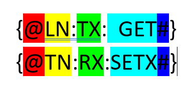
Figure 4: The Get Light Level and Set Light Threshold Commands
The light node uses the I2C protocol to communicate with an Adafruit lux sensor. The node itself is fairly simple and currently two functions, a set and a status function. The light node continuously polls the lux sensor for data using a blocking function, and then writes to an LED to turn the LED brighter when the lux sensor detects low light and vice versa. The light node utilizes the provided Adafruit library for reading from the lux sensor. Note that the I2C address for the light sensor is 0x29.
When a status request is received by the light node, the most recent lux sensor data is then sent back to the hub arduino and processed by the PIC32. When a set command is received, the threshold for the LED output brightness is adjusted either to a fixed pre-set level ('1'-'9' correspond to 10-90, and 0 for LED always on), or to the current light level ('S') based on the last command data byte. Future improvements to this node would distinguish requests commands between returning the light level, and checking on the status of the LED by returning the already-measured voltage between the LED and its series resistor, in order to return whether or not the LED is still present and turned on.
One special feature for the light node is that we sometimes had issues receiving radio data. Frequently, the radio would receive the first message after reset, and then never receive any more messages, valid or invalid. To mitigate this issue, the light node powers down the radio and re-writes all of the initialization register after each loop iteration that no message is received. Note that this occurs approximately once every 100ms, the length of the light integration time of the lux sensor. Although this only seemed to be necessary a fraction of the time, it never appeared to have a negative impact on performance and so would be recommended to be used on all nodes in the future.
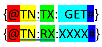
Figure 5: Temperature Get and Desired Temperature Set Commands
The temperature node is very similar to the light node in its operation, although it does not reset its radio in the same way. The temperature is read from a small analog temperature sensor, the LM35, and thus requires no extra communication. When a message asking for data is received the node simply responds with the most recently read data on the analog input pin, converts it into degrees Fahrenheit, and sends it back to the hub. The temperature node also can receive a set command which sets a desired temperature internal variable, although this variable's value is not currently used.
The PC GUI is a gui made in python using the tkinter library. For ease of use and creation we wrote a custom GUI class which wraps most of the tkinter functions in generic methods. These methods allow for the same call back function to be assigned to multiple buttons. Additionally, they also allow for one line creation of GUI components. The GUI works by reading in data sent by the arduino over UART to the PCs usb port. The data sent is framed with a ‘\x12’ to begin a message and a ‘\x13’ to end a message. This framing has proven to reduce errors in transmission and in our testing we experienced close to zero errors. As such the GUI reads in data until the ‘\x12’ character is found. Once found it then stores every byte read into a buffer until the ‘\x13’ character is reached. Similar to the PIC32, once the data has been read into the buffer, the data is then parsed to determine which node the data comes from by comparing the values in the second set of bytes to the IDs of each node on the network. The parser uses the semi-colons in the encoding format to determine when one section of the message ends and another begins. When data corresponding to a certain node is received the online status for that particular node is also set to allow the user to know that node is functioning. The GUI was designed to display the same information as the PIC32 and thus can be used interchangeably in the event that one does not have a TFT.
A video demonstration of the final result can be seen here:
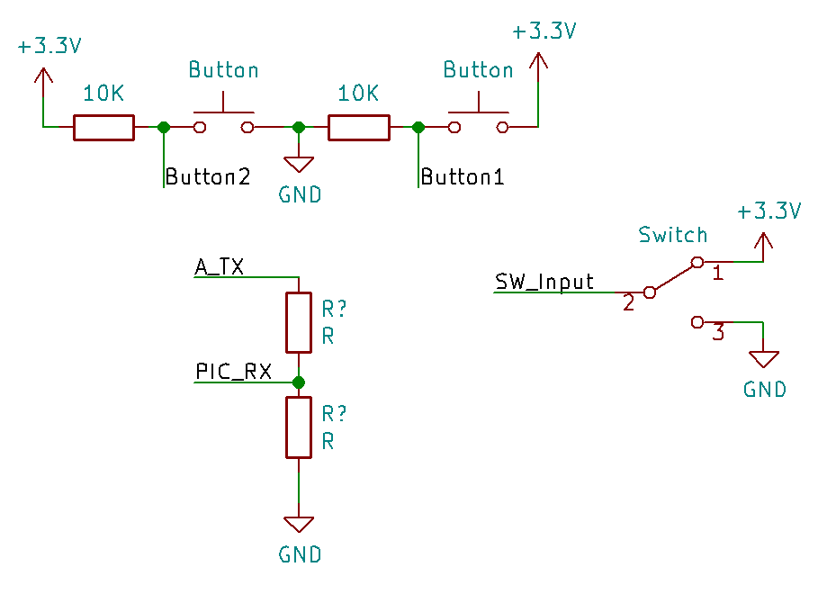
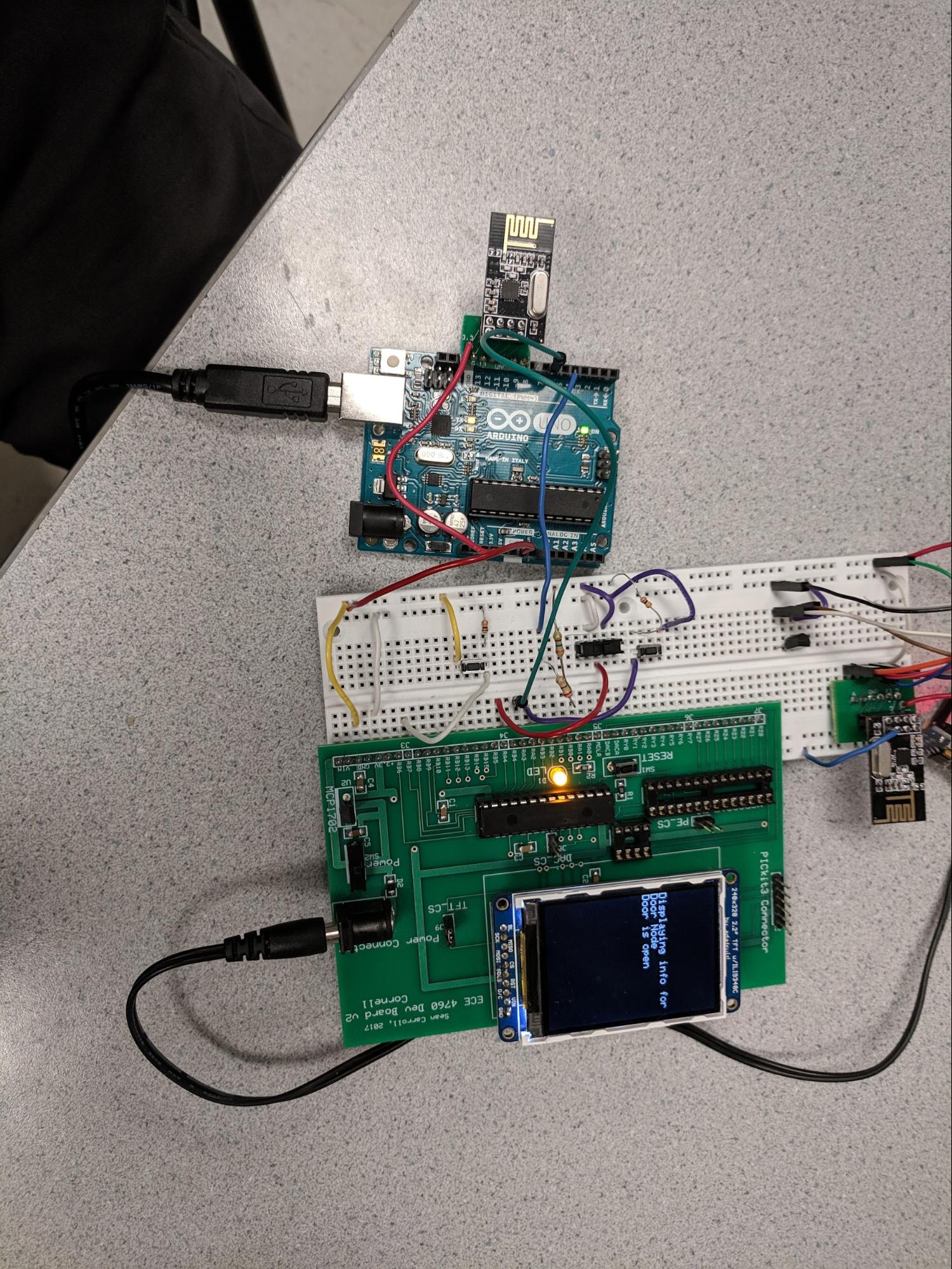
As seen in our demonstration video, we were able to communicate fairly reliably and wirelessly between the hub and the three nodes, with each node reporting its data accurately, and the door node closed the door after a door closing command was sent from the main hub. For still photographs of our project, see Appendix B. Some drawbacks include an extremely large latency on the order of 1 to 3 seconds, as well as occasional screen flickering on the TFT when new UART packets were sent and received. In addition, approximately one in five radio packets were dropped or mis-written over UART, forcing our code to repeat transactions multiple times. Since our code needed to accommodate some imperfection, the offline detection functionality on the hub's node overview display screen sometimes took over 20 seconds to report that a node had gone offline, depending on the timing of the node disappearance. The most obvious area for improvement is in better hardware integration, specifically relating to the build quality of the door demonstration, as well as moving some of our built circuitry from breadboards and jumpers toward soldered protoboard circuits for increased permanence, since our product is meant to be able to last, untouched, for months or years. Overall our project mostly met the expectations we had when we began. Originally we had planned to use the PIC32 as the main processor for each node; however, as we struggled to get the nrf2401+ modules to function correctly we ultimately had to abandon the use of the PIC32s except for the main hub. However, despite that we managed to successfully create a IoT home monitoring system consisting of a main hub and three nodes, each of which are able to send and receive data from the hub with a fair amount of reliability. Ultimately we would like to expand the capability of our network from a star network to a mesh-network. Accomplishing this goal would allow us to have nodes that are not in the wireless range of the main hub by instead passing along messages through other nodes. However, several things would need to be done in order to accomplish this. Our project adheres to the IEEE code of Ethics. The system itself is designed so the only real interaction any person would have with the system is through a PC or the built in display and hardware buttons and switches. As such there should be no risk of direct harm to a person through the use of our project, although future designs should make use of more accessible inputs, such as larger text on the GUI and more easily toggle-able switches. It would also be useful to have a feature targeting the vision impaired which would allow the currently displayed elements to be read aloud. Another thing to consider moving forward would be how to ensure that our system is secure. As we move forward with this project one of the likely next steps would be to add internet access so that one can manage their home when they are away. However, this comes with the added risk of outside attacks. To prevent this we would most likely disable certain functionality such as turning on the oven, or opening the garage door unless a specific pass code/2-factor authentication is given. One of the larger components of this project is the wireless communication between our central hub and the various nodes. Today there are many rules and regulations which govern broadcasting and wireless comms. For our wireless communications we used a nRF24L01+ 2.4GHz wireless transceiver module. According to the Federal Communications Commission (47 CFR 15) our module classifies as a Class B transceiver meaning that it is intended for residential use only. Our modules are also limited by FCC regulations to have a peak transmit power that shall not exceed 100 microwatts multiplied by the square root of the emission bandwidth in hertz. As our module operates in the 2.4 -2.5GHz range this means that it must have a peak transmit power of less than 3 watts which is the case as each radio draws less than 15mA on transmit. The group approves the video for inclusion on the course youtube channel The group approves this report for inclusion on the course website Note that the connections on the Sean Caroll Big Board are not shown for clarity, including the on-board LED connected to Pin RA0. Assume that power is supplied to the PIC32 through a wall adaptor to 4.5Vdc, and to the Arduino Uno through a USB A to USB B cable connecting to the GUI-enabled laptop. Also, note that the Arduino Uno's logic level is 5V, whereas the PIC32 is at 3.3V! Therefore, we require a voltage divider between the Uno TX and PIC32 RX. Figure 6: PIC32 Surrounding Circuitry Figure 7: Additional PIC32 Supporting Circuitry For each Arduino Nano, power is supplied through a USB A to USB Mini-B cable connected to an external power bank. Note that the Arduino Nano pins are chosen such that a single Nano could read from all three input sensors. Figure 8: Door Node Schematic Figure 9: Temperature Node Schematic Figure 10: Light Node Schematic Figure 11: Main Hub Figure 12: Progression of Hub Node Overview Display as Light Node Disconnects Figure 13: Light Node Figure 14: Door Node Figure 15: Temperature Node (Temperature sensor is black triangle in breadboard) Figure 16: TFT Display on Temperature, Light, Door Display Modes Item Vendor Total Cost PIC32MX250F128B Lab rental $5 Big Board Lab rental $10 TFT LCD Lab rental $10 Breadboard x2 Lab rental $12 Wall power supply Lab rental $5 Arduino Uno Rev. 3 Arduino.cc (previously owned) $22 Arduino Nano x3 Amazon.com $12 Makerfire NRF2401+ modules x4 Amazon.com $4.80 TSL2591 Lux Sensor Adafruit Product 1980 $6.95 Magnetic Contact Sensor Adafruit Product 375 $3.95 Parallax Continuous Rotation Servo Lab rental $15.00 LM35 Temperature sensor Lab rental $0.56 Jumper Cables x35 Lab rental $3.50 Various wires, cardboard Lab rental, Miscellaneous Free Total Cost $110.76 Anthony Viego Kevin Ying
Conclusion
Expectation vs Results
Future Work
Ethics and Safety
Legal
Appendix A
Appendix B
Schematics
Photographs
Bill of Materials
Code
Work Distribution
References: