For our final project, we built a 2 axis robot arm with a capacitive sensor on the final member, which will
allow the robot to detect a person near the robot. When there is an object detected, the arm will
stop depending on the measured capacitance. The purpose of this
type of sensor is to allow robots and humans to work in the environment safely.
Functionally, this product will allow a user to move around the robot arm with
potentiometers to complete a task as desired. In addition to that, the user can
work alongside the robot with the risk of injury mitigated by the capacitance sensor
on the robot.
High level Design
The overall design of this project is broken up into three interconnected parts: the mechanical robot
arm, electrical hardware including the capacitive sensor, and the software which runs on the PIC32.
The robot design is based on using servo motors connected directly together via 3d printed parts.
Each of the servois controlled by a PWM signal from the PIC32 processor. Each joint has a corresponding
potentiometer with a current-limiting resistor that the user can use to control the position of the arm.
To do this, we used the on-board ADC to determine the current potential of the potentiometer. From there
we converted it to a % duty cycle to control the servo motor position.
For the capacitive sensor portion, we used copper foil surrounding the arm (a rod) that acts as a very
simple
capacitor. We have a function to measure the capacitance of the foil by charging it and measuring the
voltage
through ADC. The CTMU charges the foil for certain amount of time with pre-set current so we have the
charge.
Then we can calculate the Capacitance using the formula C = q/v. After reading the capacitance, we use a
software
low pass filter to give us a steady and accurate reading with minimal gitter. If the change in
capacitance is over
a certain threshold, that indicates a person has gotten very close to the robot. Once this occurs, the
robot arm stops
all movement until the user has moved away and the capacitance reading is back to its original reading.
One of the
difficulties in this process is that different environments and robot positions lead to a different
nominal capacitance
which makes tuning of our system difficult but vital to our project’s success.
On the hardware side, one of the biggest trade offs we made was due to our limited time and budget
constraints.
The robot arm is less aesthetically pleasing than we would have liked, but we wanted to focus our
efforts on the novelty
of using capacitance on a robot arm to sense a person. Additionally we used cheap servo motors, which
worked well for our
application, but do not have as smooth operation as it would be for a final product.
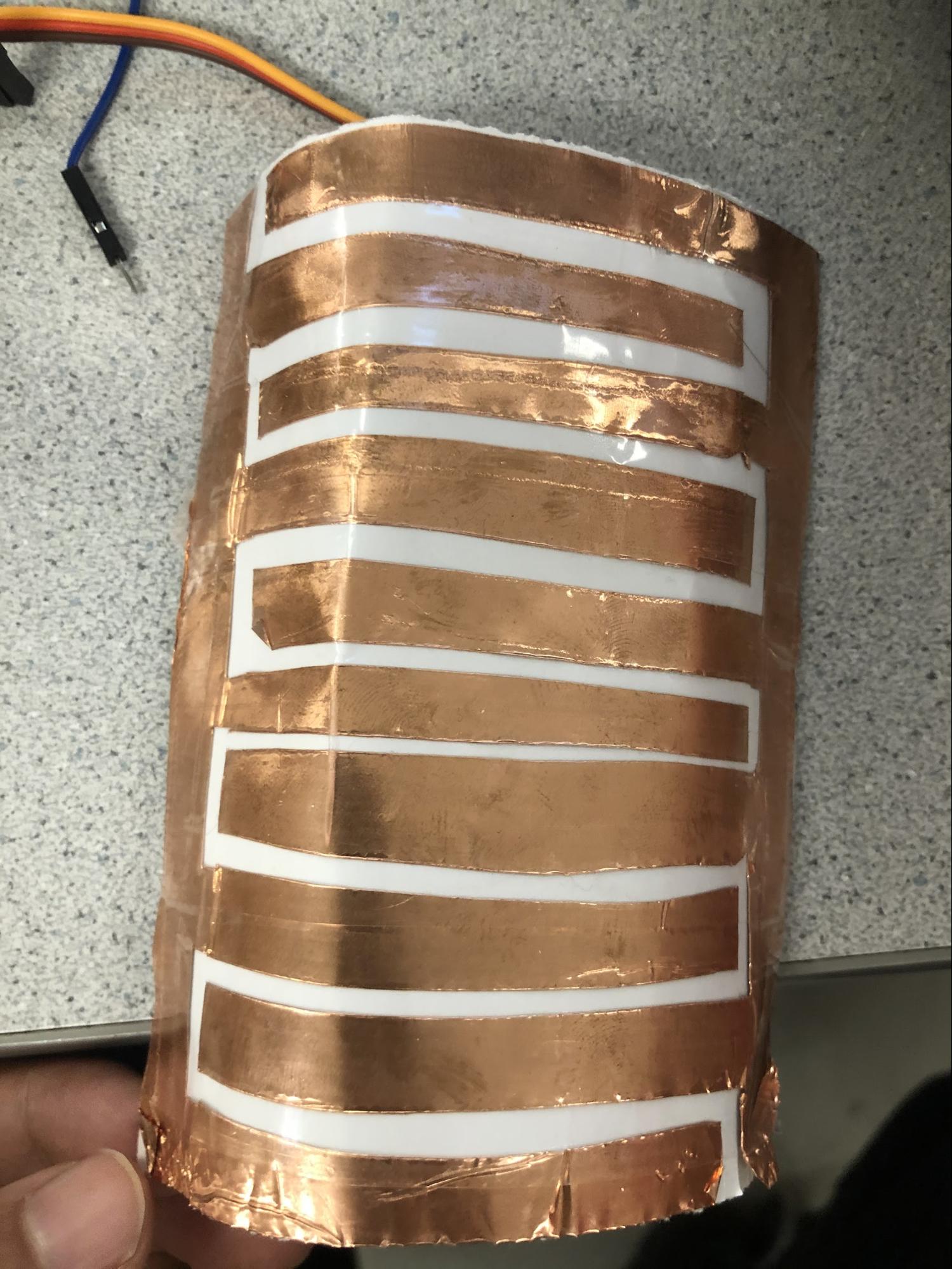
In designing the capacitive sensor, we brainstormed a few ideas and made various prototypes. The first
full-scale prototype
we created involved a network of intertwining lines that were separated by a small gap to keep the two
circuits separate. In this
design, we would use a more traditional-looking capacitor where one end is the anode and the other the
cathode as seen below.
Fig.1 - copper foil with pattern
We had great success with this prototype where we were able to get clear and consistent readings. Below is a
table of our test on this design.
Distance
ADC Reading(low pass version)
from 0 to 1023
Far Away
124-128
touching(cupping)
26-30
1cm flat
108-111
2cm flat
111-115
3cm flat
114-119
0.5cm flat
102-104
0.1 flat
94-99
1cm cupping
101-102
2cm cupping
104-107
3cm cupping
111-115
0.5cm cupping
93-97
0.1cm cupping
79-83
Although we were able to clearly read the capacitance change, we thought we could
do better. Our final design was ironically
our first idea and also the simplest of all the designs. This design consists of a single strip of
copper foil wrapped around the arm as seen below.
We believe this is the best design due to its large surface area since capacitance is linearly
proportional to surface area.
Fig.2 - Plain copper foil
We again tested this with the same type of tests with the following
results:
Distance
ADC Reading (low passed version)
from 0 to 1023
Far Away
101- 105
Touching (cupping)
43 - 46
1cm
91-95
2cm
96-100
3
99-102
.5
90-92
.1
80-83
1cm cupping
88-90
2cm cuping
93-96
3cm cup
94-99
.5 cup
82-85
.1 cup
78-82
When comparing the two final designs, it is clear that the single copper foil
design has a greater change in
capacitance with a hand near it. With this knowledge in hand, we were able to focus on the software
component of this project.
Hardware Design
3d printed parts
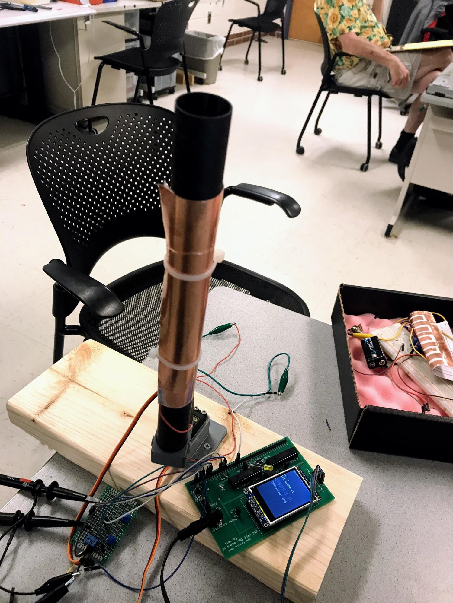
Our physical design consists of two servo motors with 180 degrees of rotation connected together
to make a simple arm with two degrees of freedom. The base motor is mounted with a 3D printed part
onto a piece of 2x6 wood which serves as a base to keep the arm in place. Connected to the base servo
is another 3D printed mount which connects to the second servo motor. Finally, a final mount connects
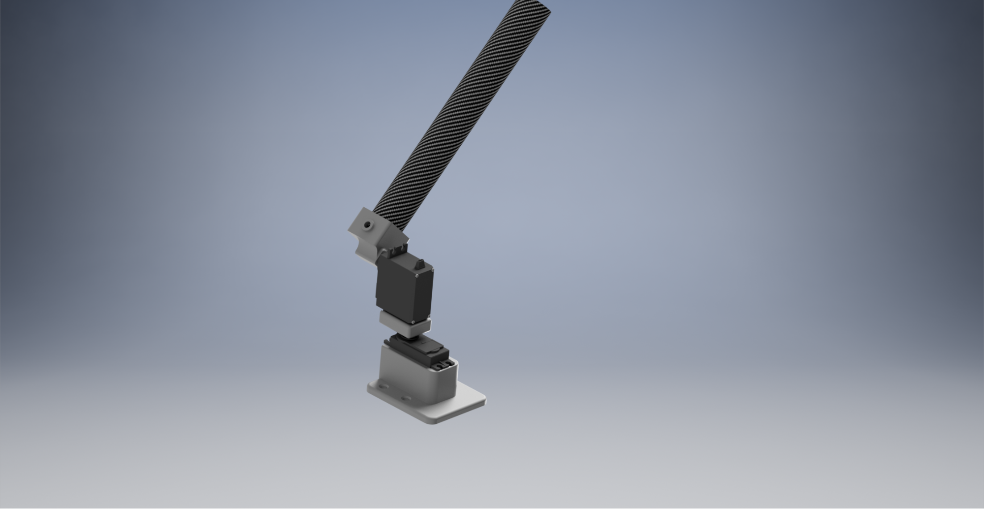
the second servo to the arm which is simply a piece of carbon fiber tubing. Below is a diagram of the
robot arm made.
Fig.3 - Rendered Image of 2 Axis Robot Arm in Autodesk Inventor
Each of the pieces that were 3D printed were made using Autodesk Inventor. The design for this was to
be as simple and effective as possible while using minimal material. The bottom piece has four slots
for wood screws to mount the piece to the wood base in addition to 2 5mm holes to place threaded heat
set inserts for M3 screws. Each part made has these slots which allows us to easily attach the pieces
to the motors and the carbon tube.The image above shows the design as rendered which we did before
building the prototype.
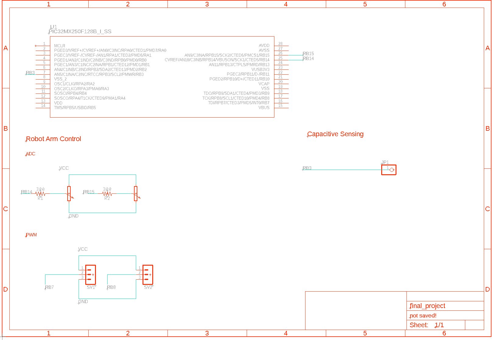
Hardware Components Overview
Prototyping Board
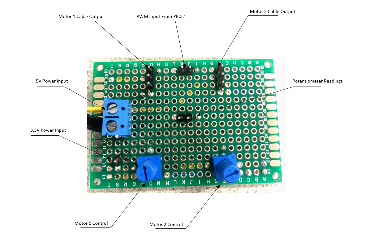
In addition to the robot arm hardware, we also designed a simple soldered prototyping board
which allows us to easily connect and disconnect the PIC32, motors, and power supply.
Additionally, it made the control of the robot very clean and consistent without any
possible loose wires.
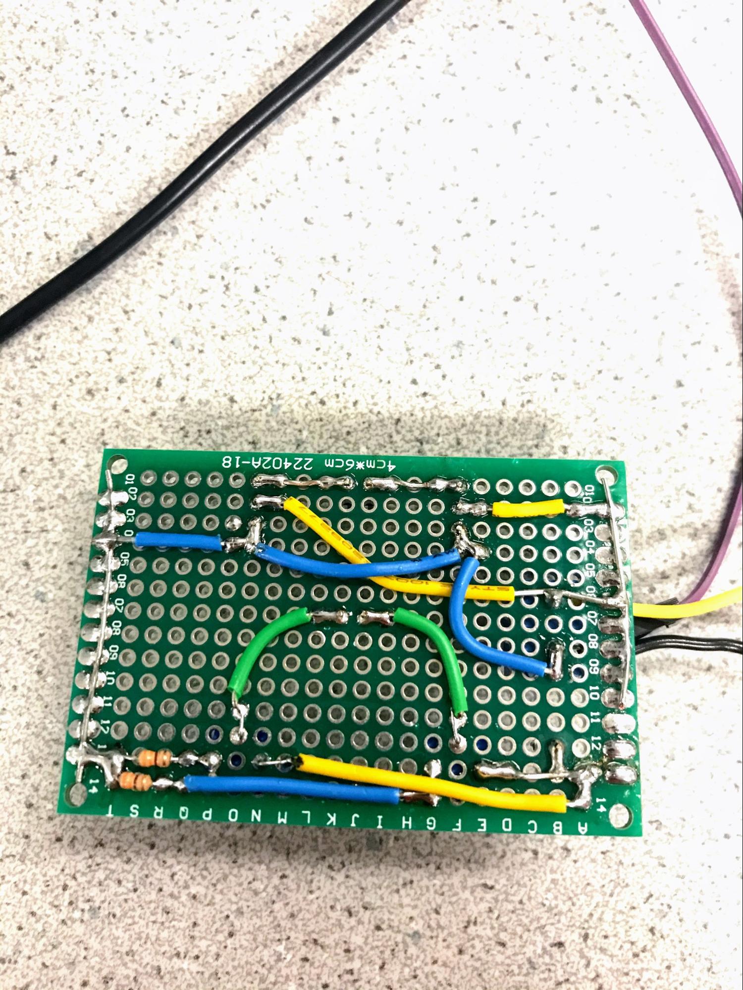
Fig.4 - prototyping board
As shown in the diagram, the user uses the two potentiometers on the bottom to control the position
of each joint of the robot. The power to the system is provided by a power supply connected by the
screw terminals on the right side. Additionally, a 3.3V power line is attached near the potentiometers
to allow the ADC to read the potentiometers as seen in the center of the board. The user connects the
two PWM outputs from the PIC32 to the board directly. Finally each motor connects easily to this board
completing all of the circuitry.
Fig.5 - Image of wiring of the protoboard
The figure above depicts the wiring of the protoboard described earlier. Each of the potentiometer
are connected to the 3.3V line and ground via a 330 Ohm pull down resistor to ensure there are no
current spikes which could damage the PIC32 board. Aside from this, the rest of the wires are just
basic connectors making sure all of the headers have power as needed.
Software Design
Software Low Pass Filter
We defined alpha = 0.98 at the start of our program to filter out high frequency
noise of two ADCs. Another reason of such high ratio would be explained in the CTMU section. Using the
formula signal = alpha * oldsignal + (1- alpha ) * newsignal, any signal can be effectively low-passed using
software. We use the same low pass formula to low pass CTMU but with alpha set to 0.9 since we want a faster
response to the proximity.
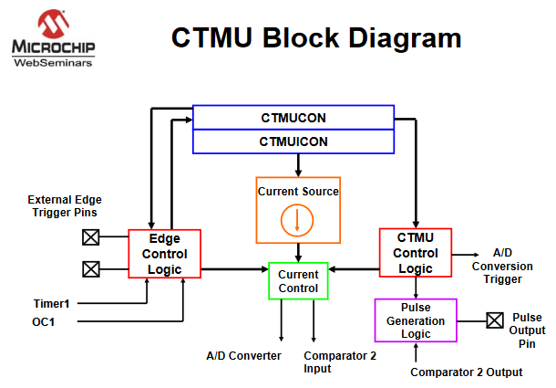
CTMU
The CTMU(charge time measuring unit) module is the heart of our project. The CTMU act
as a current source: it would first discharge the foil, then charge the copper foil for 2 microseconds with
5.5uA. And finally measure the voltage on the foil. The CTMU offers four options of current: 0.55uA, 5.5uA,
55uA and 550uA. By experimenting with our copper foil and referring from the final ADC value, we found that
0.55uA would be too small: the final ADC reading is around minimum. 55uA and 550uA would be too large: they
always gave us a reading of maximum. To approximate the 2 uS charging time, we used the code from captain
Bruce.
CTMU would work with only one analog pin connected to the foil. We don’t have
many analog pin available to use because of the TFT screen. The analog pin we chose was AN5,
corresponding to the RPB3 on the big board.
Now with ADC value, we can calculate the final capacitance.
However, when we were writing the code to detect human proximity, we found that using
capacitance for proximity detection was redundant since capacitance was derived from ADC reading. Working on
ADC directly would be more efficient.
We tried different approaches for detecting human proximity. The most naive way of
doing it would be setting a threshold: under which would be a catch. Then we just stopped reading ADCs
values from potentiometers and it would stop the arm. This method face one problem: the capacitance of the
foil was unstable even after low passing. We also observed that we achieve the highest ADC reading when the
arm was vertical to the table (around 100) and lowest when the arm was parallel to the table(around 90). The
problem may come from the distance between arm and table would alter the capacitance. If we set the
threshold too high, moving toward table would stop the arm. If we set the threshold too low, it might be too
late for the arm to stop.
To avoid the above problem, we tried detecting the proximity with a derivative term.
By recording differences of a series of low passed ADC readings. If several consecutive negative results
were detected, it mean human proximity. However we never got this method to work by tweaking around the
parameters. The problem may come from the fact that the thread was running so quickly that the number of
readings we recorded was too small.
But then we realized that the biggest problem we need to solve was that the arm was
moving too quick and it might be the reason that we couldn’t stop it before. After a discussion of how
to make arm move slower, we came up with different ideas like moving the arm to destination in steps but
eventually we found that we can slow the motion of the arm just by simply low pass ADC readings with high
alpha value.
After slowing down the motion by setting alpha from 0.8 to 0.98, the problem we had
that the capacitance of the robot arm was changing with its position also disappeared. It might be due to
the reason that the speed of the arm slowed from an instant moving to a several seconds process. Then we
tested the arm with naive threshold approach and it worked with both of our hands. When the CTMU get
an ADC reading below the threshold, we set a variable ‘prox’ to 1 which mean human proximity
detected. Two ADC readings for PWM controls would always check ‘prox’ value first and proceed if
its 0.
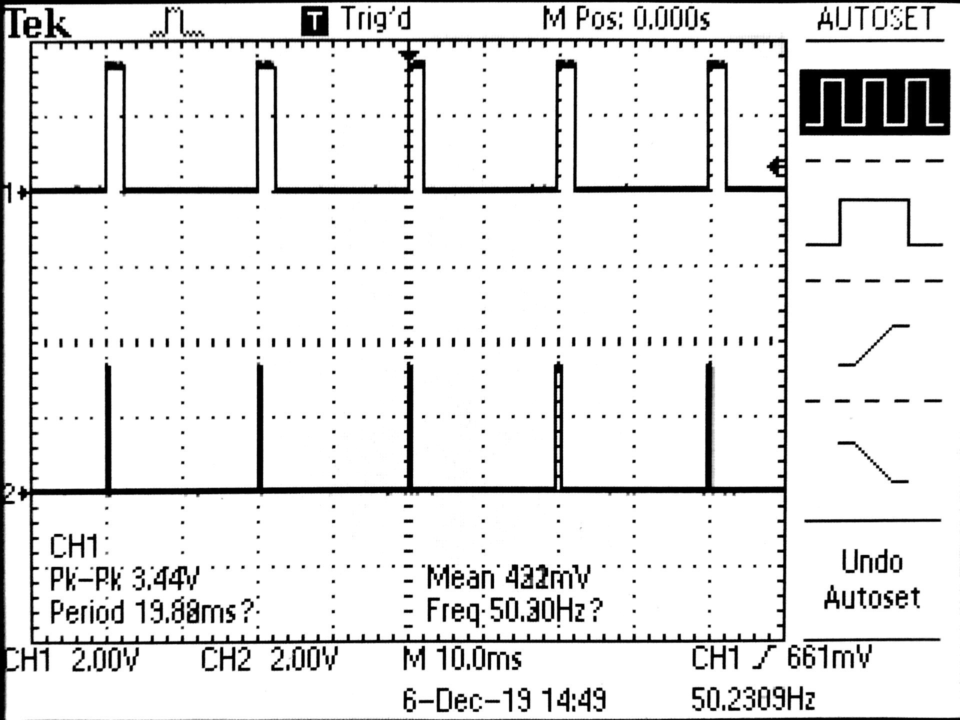
PWM
We used pulse width modululus to control the position and speed of the servo motors
in our system. The motor we used in the project has a pulse period of 20ms. And duty ratio from 0.5ms to
2.5ms. We had the timer2 running at 40Mhz. In order to get a pulse period of 20ms, we need 800000 counts for
each period. By setting prescaler to 256, we got a range of 800000/256 = 3125 range of duty cycle. Since the
duty ratio should be 0.5ms to 2.5ms. The corresponding duty we should set should be from lowest: 3125/40 ~=
78 to highest 3125/8 ~= 390. The formula we used in the code was:
The image above shows the two PWM signals running simultaneously with the top signal being at
2.5ms and the lower at .5ms. Both of the pulse widths are significantly smaller than the major period of
20ms.
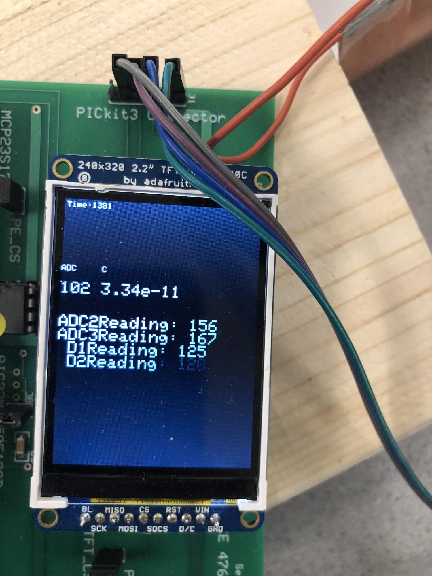
TFT
We displayed all the ADC readings and calculated capacitance to the TFT screen.
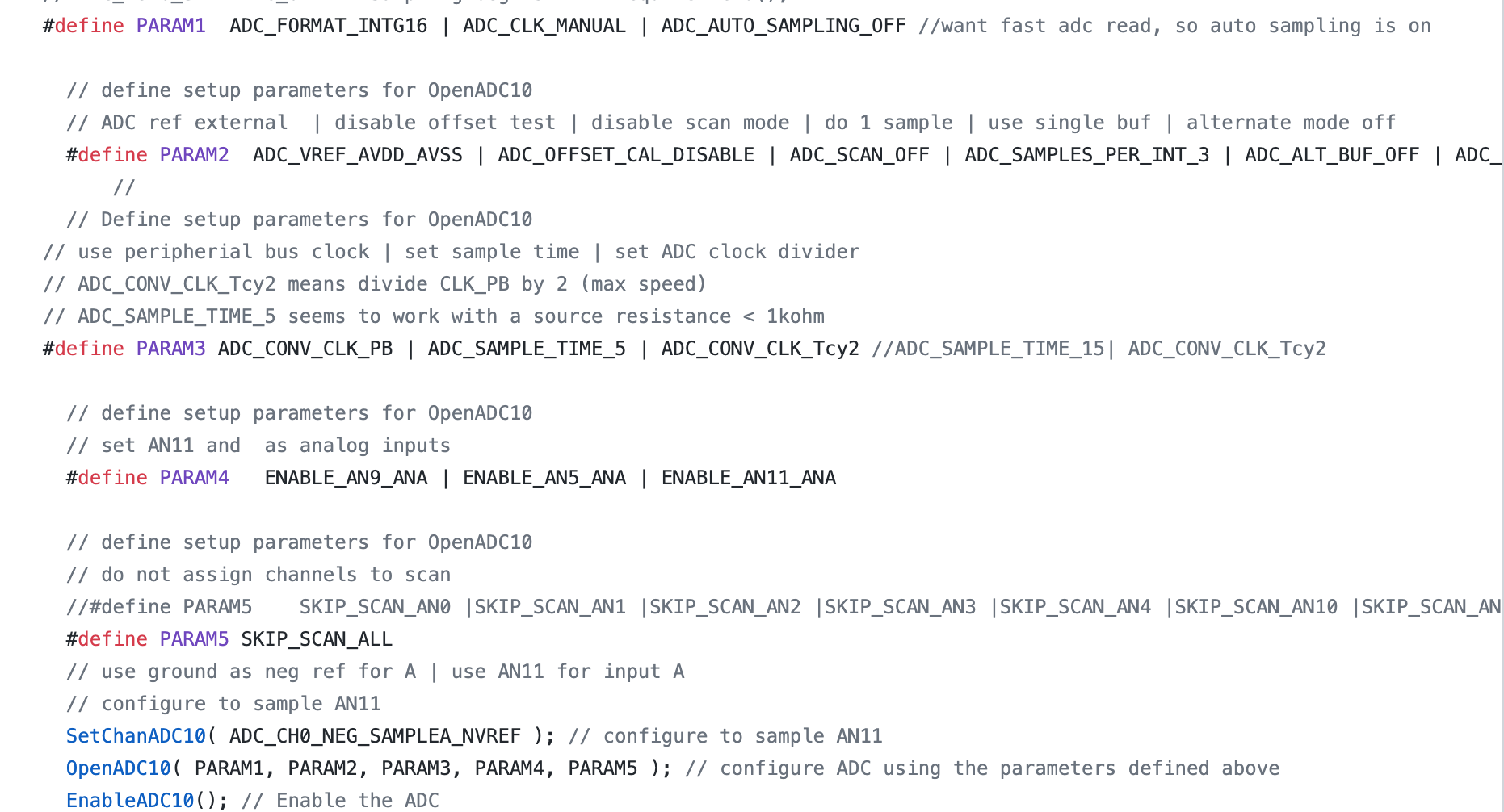
ADC
Initially we were trying to make 3 motors work at the same time but we found out that
we only have 3 analog pins left that we can use on the big board since we were using TFT screen. One is
needed for CTMU so we can only have 2 analog pins left for PWM control. Two analog pins we chose for ADC
readings were AN9 and AN11, corresponding to RPB13 and RPB 15. Since we have 3 ADCs, we could not do it with
sampleA and sample B. We also tried scan mode and it didn’t work either. We chose manual mode
eventually, for every ADC reading, we set the channel to that pin, acquire, convert, and read. The final
parameters for enabling ADC was like this:
Note that we might make a mistake that we were doing 3 samples instead of 1 by
setting ADC_SAMPLES_PER_INT_3. Which may lead to the biggest problem in our project.
Compiling it Together
We wrote everything in one thread in the final version of the project. However, we
wrote two ADC readings and CTMU in 3 different threads. For this version, we have many yield through out
each thread. It worked fine initially and displayed 3 ADC values correctly but when we tried to make
any change to the code, for example: changing how many ms to yield in any yield command, or changing the
size of text to print on TFT, would make the ADC reading for CTMU not valid at all. The ADC reading went
from 0 to 1023 randomly. However, the ADC readings for PWM controls worked well as usual. Due to that
factor, we believe that the charging time of the CTMU might be different due to yielding to the other
threads. But since the thread was not pre-emptive,we questioned how the scheduler was involved during the
charging. We tried many different approaches and spent days to solve this issue. But we
couldn’t find a solution while using multithread. Then we consulted with Captain Bruce who gave us the
advice that we might want to remove all the yield and write everything in one thread to solve this issue. We
rewrote everything in one thread and it worked.
The final version consists of 2 functioning thread: One timer thread that only
updates the time on TFT. Another main thread that do all the work: First, check the variable
‘prox’, if 0, then perform two ADC readings and convert to PWM signals. If 1, then skip this
step. Then we discharge the foil, charge it and measure the ADC. From there we can set the
‘prox’ and calculate capacitance. Finally we printed all information on TFT screen.
Design Result
See our project on youtube!
The motion of the robot is very smooth after our extensive low passing of the ADC
value to control the speed. Additionally, since we have all of the calculations in one thread, the reading
of the capacitance is extremely fast. We sadly were not able to get an exact number on the speed of the
readings, but imagine it is in the range of 300-1000 readings per second. We noticed that after our
extensive tuning, when we move the robot near our body, the arm constantly is able to stop before
hitting our hand! We tested this out at two seperate locations and with the arm at different positions and
our product continued to work. The only time where we noticed an issue is if we move just a finger in front
of the arm. Occasionally the robot would bump into our finger, but once it makes contact, it halts. This is
due to the low surface area of our finger compared to an arm or hand.
Interference Concerns
Our design only contains ADC, PWM and CTMU; Since none of those functions cause any
high frequency noise, our system will be interference free for other people and devices in the area.
Conclusion
Overall we were able to meet all of our major objectives in creating this robot arm
which has fairly fluid motion while detecting and stopping when there is a human in the way of its movement.
We were very happy with how we were able to create the sensing part of this even though neither of us had
used the CTMU or implemented capativie sensing before. Although we were not able to build the system using
three joints, the main outcome was to get the sensing working well and in the future we or others can join
this technology with a higher DOF robot arm or system.
If we had to complete this project again knowing what we know now, we would make a
few changes with the system. The first would be to take more time with the design of the arm and it’s
housing. Although the arm works as expected, it is not aesthetically pleasing to look at or watch move
around. We focused a lot on the capacitive sensing and were worried that we might run out of time if we were
to design a good-looking arm. Additionally, another thing we would have liked to add is a joystick-like
controller instead of an open PCB board with a bunch of wires coming off of them.
There are many more possibilities that we haven’t explored yet. Such as by
calculating the direction of the human proximity, the robot can either follow the object, or move away from
the object. To do this, we might need multiple foils on different robot locations while keeping tracking
which direction the robot is moving.
On the software side we wrote all of our own code besides some setup code taken from
Bruce Land’s headers and from previous labs which we completed. Although the idea of capacitive
sensing is not a new or novel idea, with a little more work on the tuning of the system, it would be
possible for us to publish our work. Currently, we do not have plans to do so, but are both open to it if we
have time early next semester.
Safety Considerations
Since safety was the primary objective in creating an active sensing arm, we were
sure that the construction and operation of the arm is safe. Each component runs on 5V which is safe to
handle by any user. Additionally since the robot arm is able to sense if a person is near, our product is
able to avoid any major collisions that could cause any harm to anyone.
Ethical Considerations
To our knowledge, our project is consistent with the IEEE code of ethics and have
satisfied all 10 articles as detailed on the IEEE website.
Appendix
Appendix A
The group approves this report for inclusion on the course website.
The group approves the video for inclusion on the course youtube channel.
Appendix B
/*
* File: Final Project 12/2/2019
* Capacitive sensing Robot Arm
* Author: Bruce Land modified by Ximeng Zhang & Matt Daniel
* Adapted from:
* main.c by
* Author: Syed Tahmid Mahbub
* Target PIC: PIC32MX250F128B
*/
// graphics libraries
//#include "config.h" // new one is config_1_3_2.h as seen line 21
#include "tft_master.h"
#include "tft_gfx.h"
// need for rand function
#include
// threading librar
#include
// config.h sets 40 MHz
#define SYS_FREQ 40000000
#include "config_1_3_2.h"
// threading library
//#include "pt_cornell_1_2_3.h"
#include "pt_cornell_1_3_2.h"
// yup, the expander
#include "port_expander_brl4.h"
//#include "pt_cornell_TFT.h"
///////////////////////////////////
// lock out timer interrupt during spi comm to port expander
// This is necessary if you use the SPI2 channel in an ISR
#define start_spi2_critical_section INTEnable(INT_T2, 0);
#define end_spi2_critical_section INTEnable(INT_T2, 1);
// string buffer
char buffer[60];
//initialize control signals
static double alpha = 0.98;
int adc_val2 = 0;
int old_val2 = 0;
int adc_val3 = 0;
int old_val3 = 0;
int raw_adc = 0;
int old_raw = 0;
static float I[4]={550e-6, 0.55e-6, 5.5e-6, 55e-6} ; // current settings in amps
static float I_set;
float C;
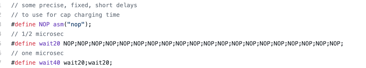
// some precise, fixed, short delays
// to use for cap charging time
#define NOP asm("nop");
// 1/2 microsec
#define wait20 NOP;NOP;NOP;NOP;NOP;NOP;NOP;NOP;NOP;NOP;NOP;NOP;NOP;NOP;NOP;NOP;NOP;NOP;NOP;NOP;
// one microsec
#define wait40 wait20;wait20;
#define Vdd 3.3
#define ADC_max 1023.0
// ==============PWM SETUP Vars / Defines//
// defines PWM
#define clockspeed 40000000 //40MHz clock
#define PWM_Pulse_Width_Ms 20
#define PWM_Pulse_Width_Cycles (int)800000/256 // 20ms clock timer
//== Timer 2 interrupt handler ===========================================
volatile SpiChannel spiChn = SPI_CHANNEL2 ; // the SPI channel to use
volatile int spiClkDiv = 4 ; // 10 MHz max speed for port expander!!
// human proximity
int prox =0;
// dutycycles for motor 1 and motor 2
int dutycycle1;
int dutycycle2;
// ==============END PWM SETUP Vars;
// ISR to clear interrupt flag for PWM
void __ISR(_TIMER_2_VECTOR, ipl2) Timer2Handler(void){
mT2ClearIntFlag(); // clear interrupt flag
}
// === thread structures ============================================
// thread control structs
// note that UART input and output are threads
static struct pt pt_timer, pt_control, pt_ctmu,pt_screen;
int sys_time_seconds ;
// === Timer Thread =================================================
// update a 1 second tick counter
static PT_THREAD (protothread_timer(struct pt *pt)){
PT_BEGIN(pt);
while(1) {
// yield time 1 second
PT_YIELD_TIME_msec(1000) ;
sys_time_seconds++;
tft_setCursor(3, 3);
tft_setTextColor(ILI9340_WHITE); tft_setTextSize(1);
tft_fillRoundRect(3,3, 180, 24, 1, ILI9340_BLACK);// x,y,w,h,radius,color
sprintf(buffer,"Time:%d \n",sys_time_seconds);
tft_writeString(buffer);
// NEVER exit while
} // END WHILE(1)
PT_END(pt);
} // timer thread
// === Screen Update Thread =============================================
static PT_THREAD (protothread_screen(struct pt *pt))
{
PT_BEGIN(pt);
while(1) {
// yield time 100 millisecond
// display varibles / warnings here at 5Hz
PT_YIELD_TIME_msec(200);
//update the screen at 5 times a second
} // END WHILE(1)
PT_END(pt);
} // screen update thread
// === Control Thread =================================================
// read 3 ADC values
static PT_THREAD (protothread_control(struct pt *pt))
{
PT_BEGIN(pt);
tft_setCursor(0, 80);
tft_setTextColor(ILI9340_WHITE); tft_setTextSize(1);
tft_writeString("ADC C\n");
CTMUCONbits.ON = 1; // Turn on CTMU
while(1) {
if(!prox){
//===============Getting the first Control ADC value ==========================
//adc_val1 = ReadADC10(0);
// adc_val1 is now CTMU
SetChanADC10(ADC_CH0_POS_SAMPLEA_AN9 | ADC_CH0_NEG_SAMPLEA_NVREF);
// PT_YIELD_TIME_msec(1); // wait
wait40;wait40;
AcquireADC10(); // start ADC sampling -- connects ADC sample cap to circuit
ConvertADC10(); // end sampling & start conversion
// wait for complete
while (!AD1CON1bits.DONE){}; // Wait for ADC conversion
adc_val2 = ReadADC10(0); // get the value for 1st control
adc_val2 = (int)(old_val2 * alpha + (1-alpha)*adc_val2);// low pass the result
dutycycle1= (int)((int)(adc_val2 * (390 - 78))/1023 + 78);// This code converts adc value to duty cycle.
// the smallest duty cycle is 78, highest is 390
// by calculating 800000 / 256 = 3125 ===> full duty cycle
// our Motor :
// Pulse Width: 500-2500
// Duty Ratio: 0.5ms-2.5ms
// Pulse Period: 20ms
// Thus, 3125/40 ~= 78, 3125/8 ~= 390
SetDCOC1PWM(dutycycle1);
old_val2 = adc_val2;
//===============Getting the second Control ADC value ==========================
SetChanADC10(ADC_CH0_POS_SAMPLEA_AN11 | ADC_CH0_NEG_SAMPLEA_NVREF);
//PT_YIELD_TIME_msec(3); // wait
wait40;wait40;
AcquireADC10(); // start ADC sampling -- connects ADC sample cap to circuit
ConvertADC10(); // end sampling & start conversion
// wait for complete
while (!AD1CON1bits.DONE){}; // Wait for ADC conversion
adc_val3 = ReadADC10(0);
adc_val3 = (int)(old_val3 * alpha + (1-alpha)*adc_val3);// low pass the result
dutycycle2= (int)((int)(adc_val3 * (390 - 78))/1023 + 78);
SetDCOC2PWM(dutycycle2);
old_val3 = adc_val3;
}// end of proximity checking
//===============Getting the CTMU ADC value ==========================
//PT_YIELD_TIME_msec(100);
// choose a current level
// using 55e-6 current
I_set = I[2];
CTMUCONbits.IRNG = 2;
SetChanADC10(ADC_CH0_POS_SAMPLEA_AN5 | ADC_CH0_NEG_SAMPLEA_NVREF);
// dischrge the cap
AcquireADC10(); // start ADC sampling -- connects ADC sample cap to circuit
// and discharge
CTMUCONbits.IDISSEN = 1; // start drain of circuit
PT_YIELD_TIME_msec(1); // wait for discharge
CTMUCONbits.IDISSEN = 0; // End drain of circuit
// start charging and wait 2 microsecs
CTMUCONbits.EDG1STAT = 1;
wait40;wait40;
// end charging
CTMUCONbits.EDG1STAT = 0;
// stop samping and start conversion
// note that in:
//#define PARAM1 ADC_FORMAT_INTG16 | ADC_CLK_MANUAL | ADC_AUTO_SAMPLING_OFF
// clock is manual and auto sampling is off
ConvertADC10(); // end sampling & start conversion
// wait for complete
while (!AD1CON1bits.DONE){}; // Wait for ADC conversion
// read the result of channel from the idle buffer
//==== checking for proximity ========================
raw_adc = ReadADC10(0) ;
// cannot be here since the noise, need low pass it first
// set to 0.6 for a faster response.
raw_adc = (int)(old_raw * 0.9 + (0.1)*raw_adc);// low pass the result
if(raw_adc < 96){ // check for human proximity
prox = 1; // if there is, set prox and stop reading ADC
}
else prox = 0; // if there is no one, resume operation
old_raw = raw_adc;
// convert raw to resistance ADC reads 11 at zero resistance
// Vref = Vdd = 3.3 ; 2 microsec charge pulse
C = (I_set * 2e-6) / ((float)(raw_adc)/ADC_max * Vdd) ; // c = q/v
// draw capacitance results
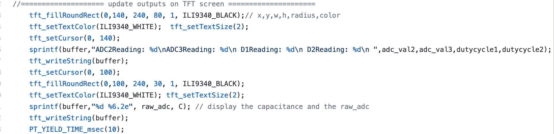
//==================== update outputs on TFT screen =====================
tft_fillRoundRect(0,140, 240, 80, 1, ILI9340_BLACK);// x,y,w,h,radius,color
tft_setTextColor(ILI9340_WHITE); tft_setTextSize(2);
tft_setCursor(0, 140);
sprintf(buffer,"ADC2Reading: %d\nADC3Reading: %d\n D1Reading: %d\n D2Reading: %d\n ",adc_val2,adc_val3,dutycycle1,dutycycle2);
tft_writeString(buffer);
tft_setCursor(0, 100);
tft_fillRoundRect(0,100, 240, 30, 1, ILI9340_BLACK);
tft_setTextColor(ILI9340_WHITE); tft_setTextSize(2);
sprintf(buffer,"%d %6.2e", raw_adc, C); // display the capacitance and the raw_adc
tft_writeString(buffer);
PT_YIELD_TIME_msec(10);
}
PT_END(pt);
}
void main() {
//SYSTEMConfigPerformance(PBCLK);
ANSELA = 0; ANSELB = 0;
// === config threads ==========
// turns OFF UART support and debugger pin, unless defines are set
PT_setup();
// === setup system wide interrupts ========
INTEnableSystemMultiVectoredInt();
// ==========the ADC===========
// configure and enable the ADC
CloseADC10(); // ensure the ADC is off before setting the configuration
// define setup parameters for OpenADC10
// Turn module on | ouput in integer | trigger mode auto | enable autosample
// ADC_CLK_AUTO -- Internal counter ends sampling and starts conversion (Auto convert)
// ADC_AUTO_SAMPLING_ON -- Sampling begins immediately after last conversion completes; SAMP bit is automatically set
// ADC_AUTO_SAMPLING_OFF -- Sampling begins with AcquireADC10();
#define PARAM1 ADC_FORMAT_INTG16 | ADC_CLK_MANUAL | ADC_AUTO_SAMPLING_OFF //want fast adc read, so auto sampling is on
// define setup parameters for OpenADC10
// ADC ref external | disable offset test | disable scan mode | do 1 sample | use single buf | alternate mode off
#define PARAM2 ADC_VREF_AVDD_AVSS | ADC_OFFSET_CAL_DISABLE | ADC_SCAN_OFF | ADC_SAMPLES_PER_INT_3 | ADC_ALT_BUF_OFF | ADC_ALT_INPUT_OFF
//
// Define setup parameters for OpenADC10
// use peripherial bus clock | set sample time | set ADC clock divider
// ADC_CONV_CLK_Tcy2 means divide CLK_PB by 2 (max speed)
// ADC_SAMPLE_TIME_5 seems to work with a source resistance < 1kohm
#define PARAM3 ADC_CONV_CLK_PB | ADC_SAMPLE_TIME_5 | ADC_CONV_CLK_Tcy2 //ADC_SAMPLE_TIME_15| ADC_CONV_CLK_Tcy2
// define setup parameters for OpenADC10
// set AN11 and as analog inputs
#define PARAM4 ENABLE_AN9_ANA | ENABLE_AN5_ANA | ENABLE_AN11_ANA
// define setup parameters for OpenADC10
// do not assign channels to scan
//#define PARAM5 SKIP_SCAN_AN0 |SKIP_SCAN_AN1 |SKIP_SCAN_AN2 |SKIP_SCAN_AN3 |SKIP_SCAN_AN4 |SKIP_SCAN_AN10 |SKIP_SCAN_AN6 |SKIP_SCAN_AN7 |SKIP_SCAN_AN8
#define PARAM5 SKIP_SCAN_ALL
// use ground as neg ref for A | use AN11 for input A
// configure to sample AN11
SetChanADC10( ADC_CH0_NEG_SAMPLEA_NVREF ); // configure to sample AN11
OpenADC10( PARAM1, PARAM2, PARAM3, PARAM4, PARAM5 ); // configure ADC using the parameters defined above
EnableADC10(); // Enable the ADC
// ========PWM Setup ==========
// turn on TIMER2
OpenTimer2(T2_ON | T2_SOURCE_INT | T2_PS_1_256, PWM_Pulse_Width_Cycles);
// Need ISR to compute PID controller
ConfigIntTimer2(T2_INT_ON | T2_INT_PRIOR_2);
// set up compare1 for PWM mode
OpenOC1(OC_ON | OC_TIMER2_SRC | OC_PWM_FAULT_PIN_DISABLE, 0,0); //
// OC1 is PPS group 1, map to RPB7
PPSOutput(1, RPB7, OC1);
// OC2 is in group 2
// allowed to output to : RPA1 RPB5 RPB1 RPB11
// RPB8 RPA9 RPC8 RPA9
OpenOC2(OC_ON|OC_TIMER2_SRC | OC_PWM_FAULT_PIN_DISABLE,0,0);
// GROUP 2, output TO RPB 8
PPSOutput(2, RPB8, OC2);
// set dutycycles for testing
//SetDCOC2PWM(2000);
//SetDCOC1PWM(2000); //for testing
// clear flag to let run
mT2ClearIntFlag();
// ========end PWM Setup ==========
PT_INIT(&pt_timer);
PT_INIT(&pt_control);
PT_INIT(&pt_screen);
// init the display
tft_init_hw();
tft_begin();
tft_fillScreen(ILI9340_BLACK);
//240x320 vertical display
tft_setRotation(0); // Use tft_setRotation(1) for 320x240
while (1){
PT_SCHEDULE(protothread_timer(&pt_timer));
PT_SCHEDULE(protothread_control(&pt_control));
PT_SCHEDULE(protothread_screen(&pt_screen));
//PT_SCHEDULE(protothread_control(&pt_ctmu));
}
}// main
// === end ======================================================