Overview
Our project consists of a 2m DotStar LED strip with 120 individually addressable LEDs and seven accelerometers with the Big Board to depict three different rides that are typically found in an amusement park: the roller coaster, the drop tower, and the bouncer. We implement 1D kinematic equations iteratively to approximate the real-world physics motion on the LED strip. We use multithreading to program the PIC32 processor on the Big Board and use SPI and I2C communication protocols to communicate with the LED strip and accelerometers, respectively. We also created a user interface in Python to easily change various settings of the rides and debugged the system using an oscilloscope and a TFT display.
Design
High Level Design
Rationale and Sources of Project Idea
Due to COVID-19, it is not safe for anyone to go anywhere that is crowded. One of the most densely crowded places is an amusement park. We wanted to bring in some of the excitement that we feel at the amusement parks into our lab. Instead of mechanically building a ride, as electrical engineers, we decided to take a more electrical approach to this: LEDs. We thought this would be a creative yet still exciting way to simulate a small amusement park.
All the amusement park rides are thoroughly calculated and calibrated to be safe and bring excitement to people. Since our rides are on a LED strip and most of the excitement comes from viewing the ride instead of riding it, we were able to simplify the physics that were involved with the rides and put more emphasis on making it look more interesting.
Logical Structure and Background Math
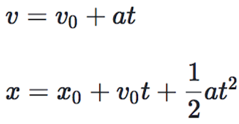
The LED strip represents an amusement park ride, and the light that travels through the LED strip represents the riders. The accelerometers are attached to the back side of the LED strip at a regular interval. The accelerometers return the angular velocities and linear accelerations in the 3-dimensional space. We first tried to calculate for the absolute position and shape of the LED strip in the 3-dimensional space from the accelerometer readings, but we soon found that this is very difficult to do. One way to do this is by iteratively calculating the updated position of each accelerometer from the initial position of the LED strip through the readings of the accelerometers. This can be done by first calibrating the LED strip at a known initial position, e.g. flat on the table, and slowly moving to the desired shape. Meanwhile, the angular velocities are converted to linear velocities through approximations and the 3D accelerations are used in the 3D kinematics equation to iteratively calculate for the final position and shape of the LED strip. However, we concluded that this approach is not preferable because these calculations involve many approximations, e.g. the radius when converting from the angular velocity to the linear velocity, and the accelerometer readings are very noisy. The approach we took was to use only the y-acceleration reading from the accelerometer that is closest to the current position of the riders, i.e. the LEDs that are on. The LED strip reduces the dimensionality that we need to take into account to 2D because the riders can only move in 1D motion along the LED strip and gravity adds another dimension to the system. There is also friction, but this is along the LED strip, so it doesn't affect the dimensionality of the system. Essentially, we only need to calculate the next LED position to turn on, which could be done with the 1D kinematics equation given the initial velocity and position along with the y-acceleration. The value of y-acceleration returned from the accelerometer depends on the slope of the LED strip. (Note that when the IMU is sitting flat on a table, only its z-acceleration should be non-zero, and more specifically should be the force of gravity). We iteratively update the y-acceleration from the closest accelerometer, current velocity of the cart using the velocity of the previous time frame along with the closest y-acceleration reading, and position from the position and velocity from the previous time frame, all using the basic kinematic equations below. Doing this meant that we did not need to calculate the absolute shape and position of the LED strip.
We believe this method allows us to achieve better performance in terms of how smoothly the riders move through the LED strip when we change the position and shape of the LED strip in real-time, because updating the entire position and shape of the ride is more expensive than updating for the new position of the riders from the previous values.
Hardware/Software Tradeoff
One step we took to get less noise in the readings of the IMUs is pass them through a low pass filter. Instead of using a physical RC filter which would add to the space and budget requirements of the project and still be noisy due to imperfect components, we neglected the four least significant bits in the readings in software. This was a simple, single line of code, but it allowed us to receive much more consistent readings in the IMUs, and hence update the LED cart's position in a more pleasing manner.
Software Design
There are three main types of threads: a thread for reading the IMU, a thread for calculating and updating the LEDs to light up in the next time frame, and threads for the Python user interface.
The IMU makes use of the IMU library inspired from the one we cited in the References section of this report. Using this IMU library, we read the values from each of the seven accelerometers on the LED strip. By assigning to global variables, we can use these values to update the next LED positions to light up in the LED thread. This way, we can dynamically change the position and shape of the LED strip and the movement of the riders will change accordingly in real-time. Also, it is important that we use the bit-shifted IMU readings rather than the raw values from the accelerometers, since the accelerometers are very noisy. Using raw values can lead to abrupt jumps in the LED positions, which leads to unnatural-looking behaviors of the riders through the LED strip. We right-shifted then left-shifted by 4 bits, and this seems to sufficiently reduce the noise, leading to natural-looking behavior of the ride. We yield this thread for 50 ms, i.e. we read from the accelerometers around 20 times a second.
The LED thread is where most of the calculation happens. In this thread, we first check the current position of the traveling light (the position of the LED that is turned on to denote where the riders are in the current time frame) on the LED strip, and use the reading of the accelerometer that is closest on the LED strip as the acceleration value. Note that the imu_reading array has length equal to the number of the accelerometers (currently 7) and has the values updated by the IMU thread explained above. Then, we check the current mode, which indicates whether it is in the roller coaster, the drop tower, or the bouncer mode. For each of the modes, a different kinematic equation is used to update the position of the traveling light in the next time frame. For the roller coaster mode, we used the equation indicated in the High Level Design section. For the drop tower mode, we use the same equation but we added an upward movement at the beginning of the ride, which travels at a constant speed, to mimic the behavior of the ride more closely. We also wait at the top of the ride for a random amount of time to increase suspense. For the bouncer mode, we use the two different equations: the same equation as the roller coaster mode when it is moving downward and the equation with the negative speed once it reaches the end of the strip and travels back up the LED strip. Because each mode behaves slightly differently even with the same equation, we controlled this through the amount of time to yield the thread until the next update to the traveling light position. For example, the drop tower drops at the same speed as the speed at which a real object is dropped, whereas we controlled the speed of the roller coaster so that we can visually examine that its behavior is clearly affected by the physics and the shape of the roller coaster. We used the Dotstar example code from the course website to send the updated values for each pixel on the LED strip (cited in the References section of this report).
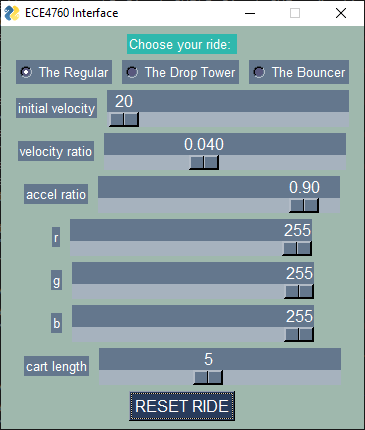
The Python user interface was created so that the amusement park could be more interactive. Users can choose the ride that they want to go on, the initial velocity of the ride, numbers to simulate friction, and even what color and how long the ride train should be. It also includes a reset button to restart the ride with the parameters that are set. An image of the interface is shown below. We use radio buttons to choose the ride, a normal button for the reset, and sliders for the remaining settings, so we include threads to support those functions in our code. These threads yield until an event happens on the interface. We used the sample code provided on the course website to help us with that (cited in the References section of this report).
The main() function handles all of the initialization, including initializing and scheduling the threads, opening an I2C channel for the IMUs, setting up each IMU (by assigning each of them a separate GPIO address pin, taking them out of sleep, and setting the accelerometer range to +-2g), opening a SPI channel for the LED strip, and turning off all of the LEDs on the strip.
Hardware Design
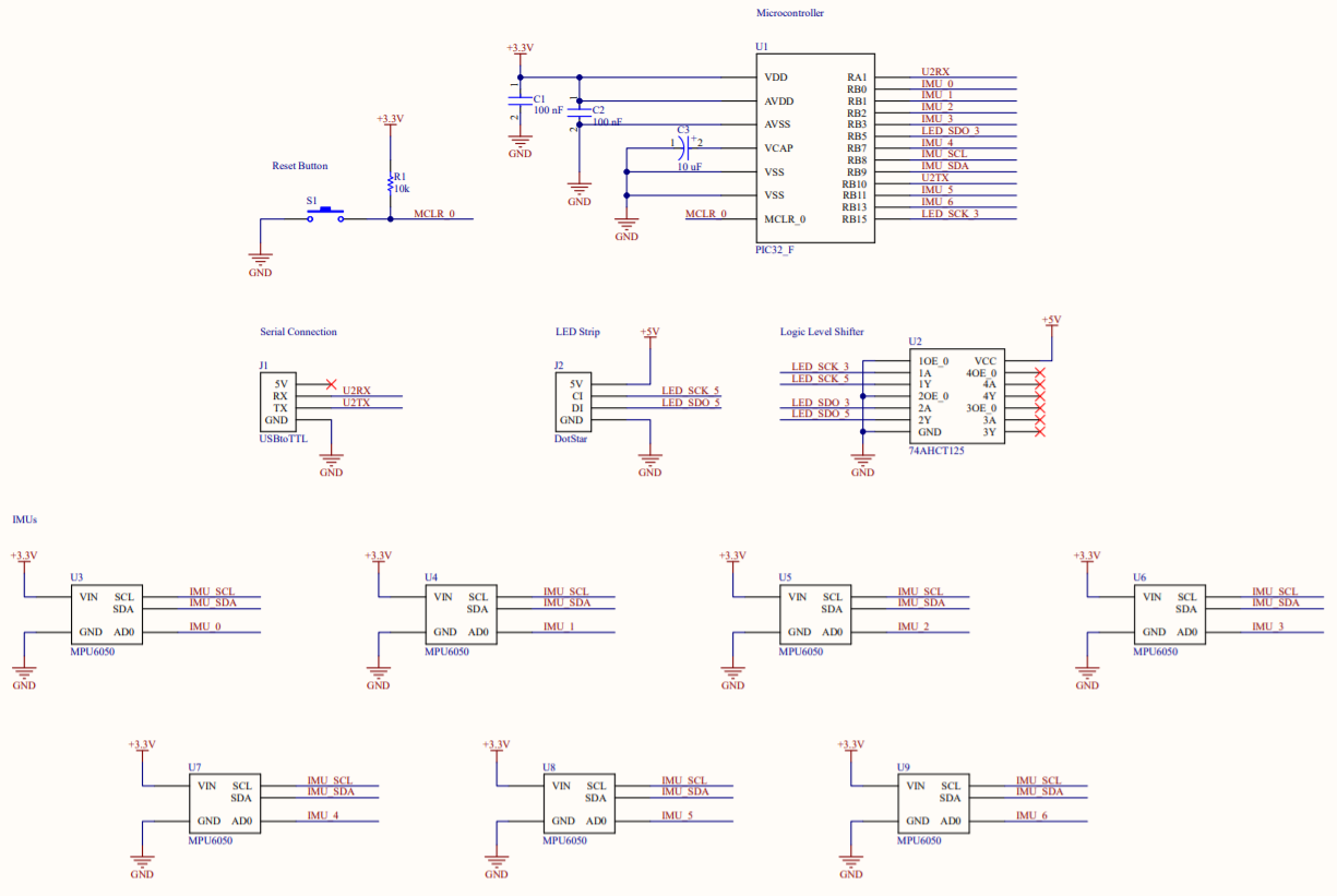
The main components in our project are the PIC32MX250F128B microcontroller, an Adafruit DotStar LED strip, seven MPU6050 IMUs, and a USB to TTL serial cable for our Python interface. A full hardware schematic can be found in Appendix C.
DotStar LED strip
The LED strip we use communicates with the PIC32 using 2-wire SPI. Because the LED strip is a 5V device while the PIC32 is a 3.3V device, we use the 74AHCT125 level shifter to translate the clock line and the data line from 3.3V to 5V in order for the microcontroller to be able to communicate with the LED strip.
IMUs
The IMUs we use are MPU 6050 chips on individual breakout boards that each communicate with the PIC32 using I2C. Each IMU has two address options, 0b1101000 and 0b1101001. One pin on the breakout board is used to toggle the last bit of its address. We are able to connect more than two IMUs by dynamically changing each sensor's addresses when we wanted to read to or write from it. We use the 0b1101000 address to communicate with the sensor. This means that when we want to talk to a specific IMU, we clear that chip's address pin and set all the others' address pins. Each sensor's address pin needed to be individually mapped to a GPIO pin on the PIC32 in order to be able to be independently manipulated. This was a pin-intensive undertaking, and we had to carefully avoid pins that were already being used by other parts of the project, such as those for the UART connection for the Python interface and the SPI connection to the LED strip.
Before we set up all of the sensors in our system, we tested them individually to make sure that they all worked. From our testing, we realized that the readings were quite noisy even when the sensor was sitting still on a surface. To reduce the jitter, we low-pass filtered the readings in software by shifting the four least significant bits of the readings out, and shifting zeros in. This reduced noise and allowed for a more smooth ride.
USB to TTL
To make our project interactive, we set up a USB to UART connection so that the user could manipulate variables in the user interface (a Python program) and the changes would be reflected in the running C program immediately, ensuring that the baud rate matches between the C program and the Python program.
Squashed Bugs, Failed Attempts, and Other Notes
One problem we came across with the LED strip was its direction. Because each LED is essentially daisy-chained in the strip, one side of the LED strip counts as the input and one as the output. Initially we were not receiving any response from the LED strip because the I2C signals from the microcontroller were not being sent to the correct side of the LED strip. After looking closer, we realized it was important to pay attention to orientation.
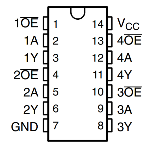
One important issue we had with our design was the PIC32 only outputting a peak to peak voltage of 3.3 volts. The LED strip required a voltage of 5 volts for both the data and clock line. After several attempts of connecting the LED strip to the PIC32 and not seeing any response, we realized that we needed to use a level shifter. The pinout of the level shifter we used (74AHCT125) is shown below. The "A" pins are the 3.3 volt pk-pk inputs from the microcontroller, and the "Y" pins are the 5 Volt outputs to the LED strip. The "OE" pins had to be grounded in order for the outputs to be enabled. Note that we only used two out of the four channels available on the chip: one for clock, and one for data.
The amount of wires we used to connect each of the sensors to the PIC and the LED strip oftentimes became overwhelming to keep track of. We tried our best to color code the wires so that we could easily tell which wire goes to which pin. We also made sure to add tape to wire openings, so they would not short. For example, the ground and power pins for the power of the LED strip were left floating since they were internally connected to the Dotstar MCU inside of the LED strip. We taped the ends of these wires so the power and ground would not accidentally touch each other and short. If there were any other wires which were stripped and we noticed they may easily touch, we taped these wires so that there was no possibility of shorting and destroying the IMUs or the PIC.
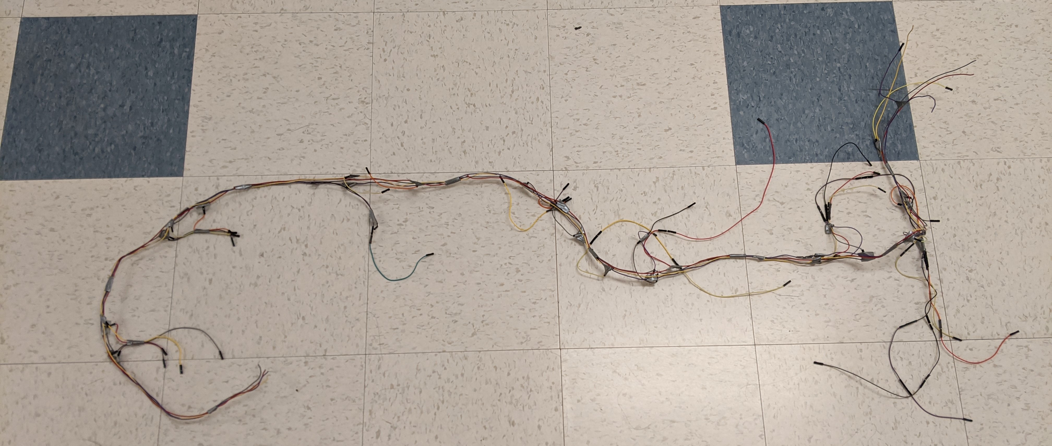
As a side note, we tried to use less wires by creating the wire harness shown below, but it ended up being even more problematic when we were trying to debug our project because of the poor connections.
One frustrating bug we encountered was not properly taking the sensors out of sleep mode. This happened as an artifact from when we had done IMU testing one by one. When we were adding sensors by mapping a new GPIO pin to each, we neglected to also initialize each of the sensors we were adding. The way the code was initially formatted caused us to only be initializing the last sensor we added, which resulted in a confusing false positive where they all seemed to be working when we added each sensor one by one (since they would all retain their state of having been taken out of sleep mode) but all of a sudden wouldn't work when we ran the same exact code again the next day and/or power cycled the big board. This problem was only exacerbated by the fact that we didn't know whether it was a hardware issue with wiring, or a software issue.
Another interesting thing to note is that the I2C protocol was intended to only be used for intra-board communication, but could be pushed to longer distances with a lower clock frequency. With a peripheral clock frequency of 40 MHz, we set our I2C clock frequency to be 100 kHz by setting the I2CxBRG register value to be 0xC2.
Results
Our project successfully was able to demonstrate three different amusement park rides with our LED strip. Our design focussed on making the entire “roller coaster” and other rides look as natural as possible. In order to achieve this, we made sure to choose yield times that were small enough so that the LED carts' positions could update as soon as possible, and the sensor readings would be read as soon as possible. We tried to eliminate any additional threads that were not needed during our final design. For example, one of the print threads, which was printing the sensor readings of each IMU to the python interface, took a long time to execute. Hence, we noticed pasues in our LED roller coaster, probably due to it waiting for everything to print out before continuing onto the other threads. After removing this, we were able to see a much smoother execution.
In order to demonstrate the "realistic" movements of our roller coaster, we tried several different configurations during the demo. We had the LED strip in the shape of a parabola, so that it would settle down close to the minimum of the parabola. We tried a loop, so that we could see that the LED cart would slow down at the very top of the loop, and then speed up on the way down.
Another important result we wanted to highlight was our free fall "drop tower" ride. This was a simple drop tower, composed of the LEDs climbing to the top of the strip, and then waiting for a random amount of time, and then falling down at nearly exactly the acceleration of gravity. We were able to demonstrate the accuracy of this by dropping a pen right as the LED cart fell down, and they dropped at nearly identical speeds.
One result of our design that slightly brings down the "natural" quality of the roller coaster is the lack of additional sensors. Since our algorithm works based on the acceleration detected by the closest IMU to the LED cart, the behavior of the LEDs in the middle of two IMUs is erratic. Hence, if we were able to use more sensors, we would have less of this behavior, since there would be less space between the sensors.
Demo
Conclusions
We believe our design accurately replicates the movement of rides at an amusement park, and we were able to demonstrate three different rides. Our final product exceeds our expectations, and we were able to create a project that could dynamically respond to our movements and orientation of the LED strip, which we had envisioned from the beginning.
As mentioned earlier, one thing we would like to improve on is adding more sensors to our design. More sensors would give our LED cart more accuracy whenever it updates its position, and it wouldn't awkwardly stop in the middle of two sensors if one is at a horizontal position. The addition of more sensors would be a simple task, but we decided to remain within a more reasonable budget for the purpose of this project.
In order to make this project also much more aesthetically pleasing, we could include additional colors while the LED cart is moving throughout the LED strip. For example, if the cart is moving faster, it can be changing colors more rapidly, and while it is moving slower it can gradually change colors to offer a visually pleasing experience for the user.
The use of sensors to get data was a great way to get more experience in using I2C devices. However, after thinking about it more and getting feedback from the professors, another way we could also get a similar effect is if we were able to use computer vision on the LED strip, and based on how it was oriented, change the velocities of the LED cart. This would require a much more software-focused approach, but could be an interesting improvement for the future.
Our design used several important concepts that we learned in class. The communication with the LED strip was through SPI, and communication with each of the IMUs were through I2C. We also interfaced with an external Python GUI through UART, which could control the color, initial velocity, and length of the cart, and the mode of the ride. We made sure to properly configure each of the threads, and were cautious to make sure that the threads did not interfere with each other when yielding between them.
We believe we meet all ethical, safety, and legal standards.
Appendices
Appendix A: Permissions
The group approves this report for inclusion on the course website.
The group approves the video for inclusion on the course YouTube channel.
Appendix B: Code
main.c
i2c_helper.h
python_interface.py
zipped code
Appendix C: Hardware Schematic
Appendix D: Budget
| Part | Unit Cost | Quantity | Parts Total |
|---|---|---|---|
| Big Board | $10 | 1 | $10 |
| PIC32MX250F128B Microcontroller | $5 | 1 | $5 |
| Header Socket | $1.40 | 1 | $1.40 |
| 5V Power Supply | $5 | 1 | $5 |
| Female Power Connector | $2 | 1 | $2 |
| Jumper Cables | $0.10 | 50 | $5 |
| DotStar LED Strip [1] | $59.90 | 1 | $59.90 |
| MPU6050 IMU Breakout Board [2] | $3.33 | 7 | $23.31 |
| 74AHCT125 Level Shifter | $1.50 | 1 | $1.50 |
| USB to TTL Serial Cable | $9.95 | 1 | $9.95 |
Grand Total: $123.06
Appendix E: Team Tasks
| Jasmin | Jenny | Aratrika |
|---|---|---|
|
|
|
References
MPU6050 Datasheet
MPU6050 Register Map
PIC32 I2C Documentation
74AHCT125 Datasheet
DotStar library
I2C library inspiration
Python interface inspiration