Introduction
Audio effects are used in nearly every recorded and live song across genres, whether its reverb being added to a vocalist or noise being filtered from a drum track. When used with guitars, they’re so ubiquitous that the interesting tones they create are often already associated with the instrument (like distortion), although they can also create weirder sounds that seem like a different instrument entirely. Guitar pedals create a lot of these effects by intercepting the input audio, usually a clean input from an electric guitar, and manipulating it into a different, often much more complex sound.
Our guitar pedal was an opportunity to utilize concepts of digital signal processing on a PIC32 microcontroller. Earlier in the semester, we worked on a sound synthesis lab to artificially simulate bird songs, and another where we read input from analog sources into our microcontroller. This project allowed us to combine what we learned from these projects by both manipulating sound and by reading external input (including audio and user input), while also letting us understand what happens under the hood when a simple guitar sound becomes a harsh distortion.
This project builds on a number of different Electrical and Computer Engineering concepts that we’ve focused on throughout the semester. On the computer engineering side, we are of course using the C programming language, interfacing with I/O devices, performing digital signal processing, and scheduling various interrupts to sample and process audio at high speeds; on the analog side, we connected numerous additional inputs and outputs including audio, potentiometers (knobs), buttons, and LEDs, and added analog circuitry necessary (specifically, a high pass biased filter) to make the signal readable by the digital side. We soldered components together and drilled into a physical container so we could house the microcontroller, breadboard, and wires in a single box.
The PIC32 microcontroller was used entirely in this lab and programmed in C using MPLAB IDE software. Testing was done using a guitar and a quarter-inch jack connected directly to our pedal, with the output connected to an audio amplifier to broadcast the manipulated sound. In the end, our guitar pedal worked as expected to successful completion of our final demo. A video of the pedal in use can be found in Appendix H.
High Level Design
For our final project, we designed and built a guitar pedal. A pedal is an electronic device that manipulates input audio signals in real time using various signal processing techniques. This can occur either in software, as a digital pedal, or in circuitry, as an analog pedal; our pedal is a digital one, which means that the audio is sampled and quantized, manipulated in software, and then converted back to an analog signal afterwards. Our final design consists of three effects that users can activate— distortion, flanger, delay, each of which is controlled by three parameters such as delay time, modulation depth, amount of distortion clipping, and so on. When a user turns on an effect, by pressing the corresponding button, the sound immediately changes, and the LED associated with that button turns on to indicate which effect (if any) is in use.
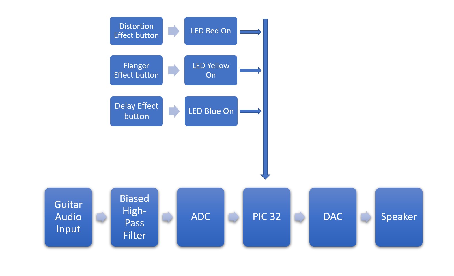
When the input signal of a guitar enters the pedal, the input signal is biased and sent to the ADC to be processed with the PIC32. After processing, the signal is sent to the DAC and a cable can connect it to an amplifier speaker. When no effect is in use, the output signal is (nearly) the same as the input one. The magic happens when the user pushes a button on the box, and the respective LED turns on. The effect is applied digitally to the signal in software within the PIC32 before being sent to the DAC, and radically alters the sound that is played from the output. Note that only one effect can be active at a time.
Our project was partially inspired by the designs of existing pedals; when determining which audio effects we wanted to implement in our design, we looked at a range of existing guitar pedals to learn which effects are commonly used by guitarists (i.e., the target market for this device). We did not model our pedal on one specific existing pedal or groups of pedals (so there are no particular copyright or patents relevant to our specific design), and there are no apparent IEEE or related standards that relate to guitar pedals. Each of the three effects that we decided to implement on our own pedal is described below:
Summary of Effects
For a more detailed description of the implementation of these effects in software, please see the Software Design section further below.
Each effect also has various parameters that can be changed using the three knobs on the pedal. The middle knob sets the mix parameter for all three effects; this value determines how much effect is applied to the input signal. A low mix means that the clean “dry” signal would be much louder in the output relative to the altered “wet” signal, and vice versa for a high mix value. The other two knobs are effect specific.
Distortion
Distortion, which gives the sound a harsh or dirty tone and is often found in rock music, is created as a result of clipping an audio signal when its magnitude goes above a fixed threshold. Compared to the clean sound, the altered audio has more aggression and bite, as a result of the higher pitched harmonics that are generated by flattening the top of the waveform.
Hard clipping is where the signal is completely pushed against the threshold and flattened entirely; it has an extremely distorted tone where the original signal may be barely recognizable. Soft clipping, meanwhile, gives a much warmer and less harsh tone with fewer high pitched harmonics, and occurs when the signal above the threshold is slightly reduced but not completely limited; this effect is called Overdrive. Our signal is pushed against the cap, but when a low pass is applied, the front of the waveform is smoothed slightly, so it doesn’t fully reach the threshold at first; rather, once near the threshold, the waveform appears to asymptote towards it (see the videos in the results section below for examples). When no low pass is applied (with the tone knob set high), we have regular hard clipping.
Our distortion effect is activated when the user presses the red button on the pedal, and the red LED will be on to indicate this. In addition to the mix knob, this effect also is controlled by the Gain and Tone knobs.
- Gain: The left knob controls how distorted the sound is. It works by changing how much the input signal’s volume is increased, or internally, by what factor greater than or equal to one by which the amplitude is multiplied. Because the clipping limit stays constant, increasing the amplitude of the input signal means that more of the signal gets clipped, making an even more distorted sound.
- Tone: The right knob allows for users to roll off some of the piercing high frequencies that are created as a result of the distortion. Especially with high gain, a lot of high frequencies are created, and these can make for an unpleasant sound, so this knob adjusts the cutoff frequency of a low pass filter that can be used to reduce these loud harmonics.
Delay
The delay effect is activated when the blue button is pressed. The blue LED turns on to signal to the user that the effect is in use. This effect plays back the delayed version of the original signal. It may sound like an echo but the idea behind this is using the output as an input. You can control this by adjusting the feedback knob to determine how much output is fed back as input. When adjusted to the max can create close to infinite sound produced with a delay. The delay time knob lets the user determine how far back in time you want to sample.
A delay is a relatively simple effect, in which a delayed copy of the signal is played back alongside the original. Generally, this creates an echo, but as the delay time decreases, the resulting sound also changes. A very short yet still audible delay, sometimes referred to as a slapback delay, can help give instruments a more complex sound in which the copy causes the original sound to almost bounce as it fades. With even shorter delay times, the duplicate sound is hard to distinguish from the original, so instead of creating a noticeable echo, the timbre of the sound changes. This can be used, for example, to help vocals sound fuller (this essentially duplicates the vocals with a copy that is playing a brief moment delayed).
Our delay effect is activated when the user presses the blue button on the pedal, and the blue LED will be on to indicate this. This effect is controlled by two knobs besides the mix: delay feedback and time.
- Feedback: Sometimes, echoes will have an echo that repeats and slowly fades away, instead of just a single echo. This is the result of feeding the echo back into the effect instead of just storing the new input signal. The feedback knob on the left adjusts how much of the echo is saved alongside the input signal. Theoretically, a feedback multiplier of 1 would mean that every input sound is added to the delay and never decreases in volume, which will often quickly turn the output into messy indistinguishable noise. Our feedback knob doesn’t allow the user to have this infinitely repeating ability, and instead will ensure the echo always is decreasing.
- Delay Time: The right knob adjusts how long after the original signal is played should the delayed signal be played. When this knob is turned up, the echo may come after a more noticeable delay (still around a quarter second), but when this knob is turned down, the delay will be so quick that it almost blends with the original signal and changes the tone. Then, by setting the knob low but not at the minimum, users can create very short yet audible delays like a “slapback” delay.
Flanger
Modulation effects are where a periodic “low frequency oscillator,” or LFO (typically a sine wave) is used to slowly and subtly adjust an input signal. The movement of the LFO gives the output signal motion even when the input signal stays constant.
A flanger specifically is one in which a very short delay (typically less than 20 ms) is applied, but the delay time is modulated by the LFO. Because the delay is so short, the output doesn’t sound like an echo like it would with longer delays; rather, the timbre of the sound is changed as the waveform begins to interfere with itself. And because the delay time is periodically changing, the amount of interference changes. The effect is often described as giving the sound a “whooshing” feeling like an airplane flying overhead. Our flanger effect is activated when the user presses the yellow button on the pedal, and the yellow LED will be on to indicate this.
Besides the mix knob, this is controlled by a rate knob and a depth knob.
- Rate: The left knob controls the speed at which the oscillation occurs, with the longest being several seconds per oscillation and the shortest being a fraction of a second. With a slower rate, the period of the effect is less noticeable, and instead the timboral change of the sound is primary. As the rate gets smaller (around a second or less), the oscillation becomes more noticeable. When the rate gets relatively small, weird byproducts of the effect start to kick in— delaying a signal is the same as sampling from previous values of the signal, and so changing that delay time essentially means that we are slowing down or speeding up the rate at which we sample; when this change is extreme, the result is a noticeable de-tuning of the sound, because the frequencies we sampled are now being played back much slower or faster than they were originally recorded. And when the rate gets even smaller, to the point where it increases above 20Hz, the period is so fast that human ears no longer hear each period, but instead hear a note of that frequency— the wave is changing at an audible frequency, which further alters the tone. (If interested in this, look into frequency modulation (FM) synthesis. It creates interesting tones by modulating the frequency of a waveform at audible frequencies. While it doesn’t use a delay, it still creates new tones like a flanger with an extremely fast rate might).
- Depth: The right knob controls how much the delay time increases and decreases by. A higher depth will lead to a more dramatic change in the sound. Especially with a higher rate, the depth also causes the periodic nature of the effect to be emphasized, because the delay time changes by a greater amount each period.
Design Trade-offs
There were some trade-offs we considered when deciding on our final design, most notably regarding the implementation of the effects in software rather than hardware. Using software allowed our design to be flexible in terms of the number and type of effects that we implemented. For example, the clipping in the distortion effect could have been achieved by connecting two diodes in parallel with a resistor (one reverse biased and the other forward biased). This setup may have performed better than our software implementation in terms of noise in the output signal, but would be less flexible in the thresholds for clipping and ability to adjust the midpoint of the signal; this would also make it more difficult to switch between effects - an analog multiplexer may have to be used to direct the signal to analog circuitry that implements different effects. With hardware we would have three times the number of knobs when compared to software numbers we used because each effect would have three dedicated knobs to manipulate its parameters. Another tradeoff was opting for buttons compared to small toggle switches. Toggle switches do provide an advantage in terms of weight but the buttons were aesthetically pleasing for how we envisioned the pedal. Unfortunately, we were unable to acquire traditional latching foot-switches that are generally used on pedals, which would make the pedal easier to press with a foot while playing guitar, but the buttons we used allowed us to coordinate the colors with the LEDs, and are larger and easier to press by hand.
Finally, because we are using the in-built DAC and ADC, we only had 12 and 10 bits, respectively. Generally, digital audio devices will want to have at least 16 bits, perhaps 24, per sample. With the PIC32 setup, it was outside the scope and timeline of this project to introduce an external ADC and DAC, considering the audio quality was still relatively clear. This did mean that our output contained some audible noise from the conversions (especially at higher volumes), and did increase the amount of quantization in the distortion effect specifically. See the Design Results section below for more details.
System Design
User Overview
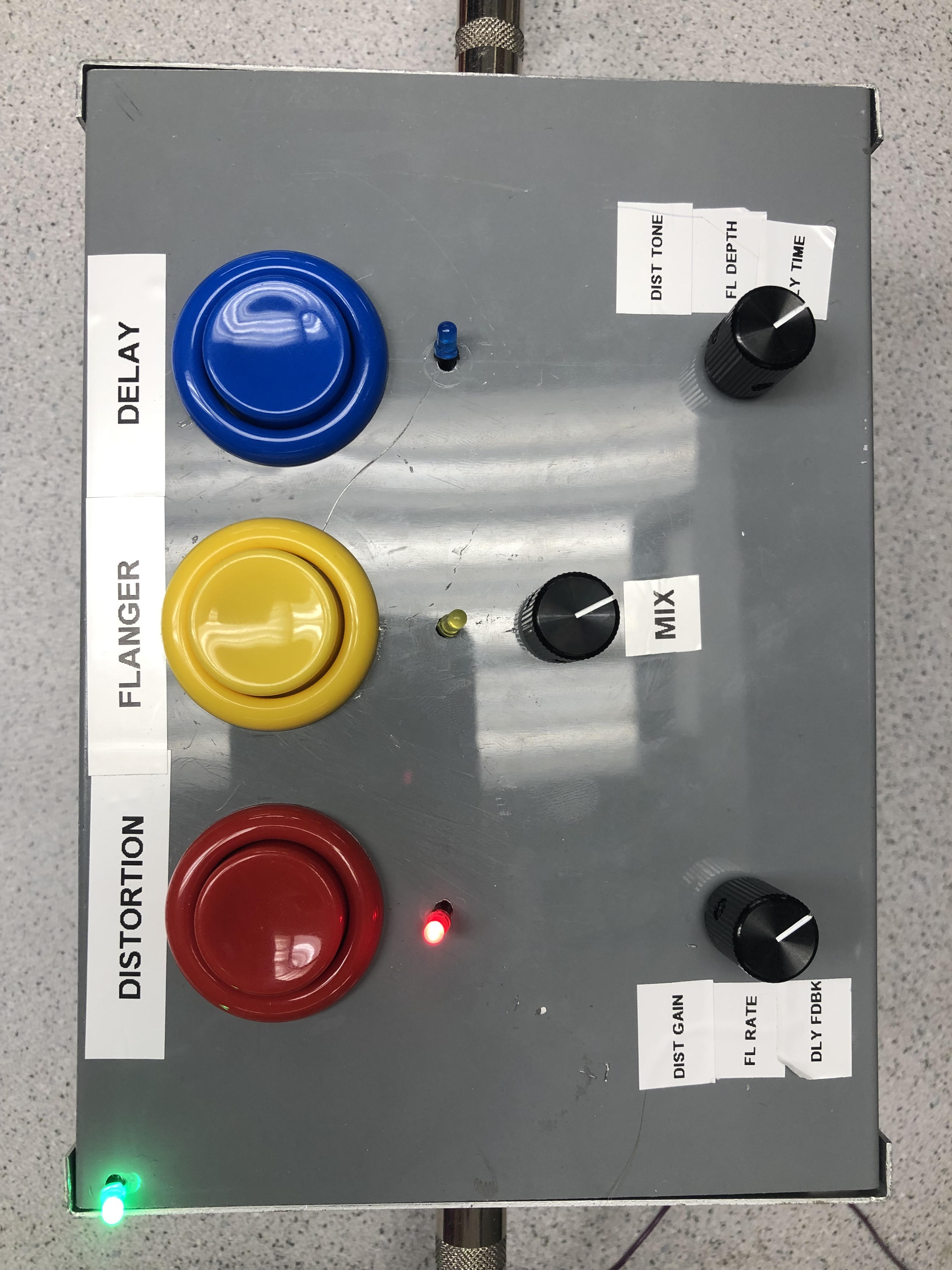
To maximize ease of use for typical consumers already familiar with off-the-shelf guitar pedals, we modeled our user interface on traditional pedal designs. To make the system portable, all of the electronics are encased in a large (7x5x3 inches) metal box; protruding from this box are a set of knobs, buttons, and LEDs that provide feedback to the user and allow them to change system parameters. To allow for interchangeability with a large majority of pedals available on the market, our device is equipped with an industry-standard ¼ inch jack for audio input and output. 5V DC power is supplied to the PIC and peripheral circuitry through a barrel connector that plugs in through a port in the back of the device. An image of our pedal can be seen above.
In the top left corner of our pedal is a green LED that indicates if the device is receiving power. Upon startup (i.e., being plugged in), the power LED turns on and the pedal begins in bypass mode: no effect is applied to the input signal. To activate an effect, the user can push one of the three buttons on the control panel; pressing the red button applies a distortion effect to the input signal, yellow enables the flanger effect, and blue yields a delay effect. Upon selecting one, the corresponding color LED will illuminate below the pressed button to indicate that the user’s input was properly registered. Only one effect can be active at any given time. To switch effects, the user can press a different button; pressing the button corresponding to the active effect will return the system to bypass mode. Each button is clearly labeled on the control panel to aid the user in identifying which effect corresponds to each button.
To change the audio parameters of each effect, the user can adjust the three knobs on the control panel. The knob value is read by software, and the pedal processes their values differently depending on which effect is active. See Software Details below for more information on the different effects.
Hardware Details
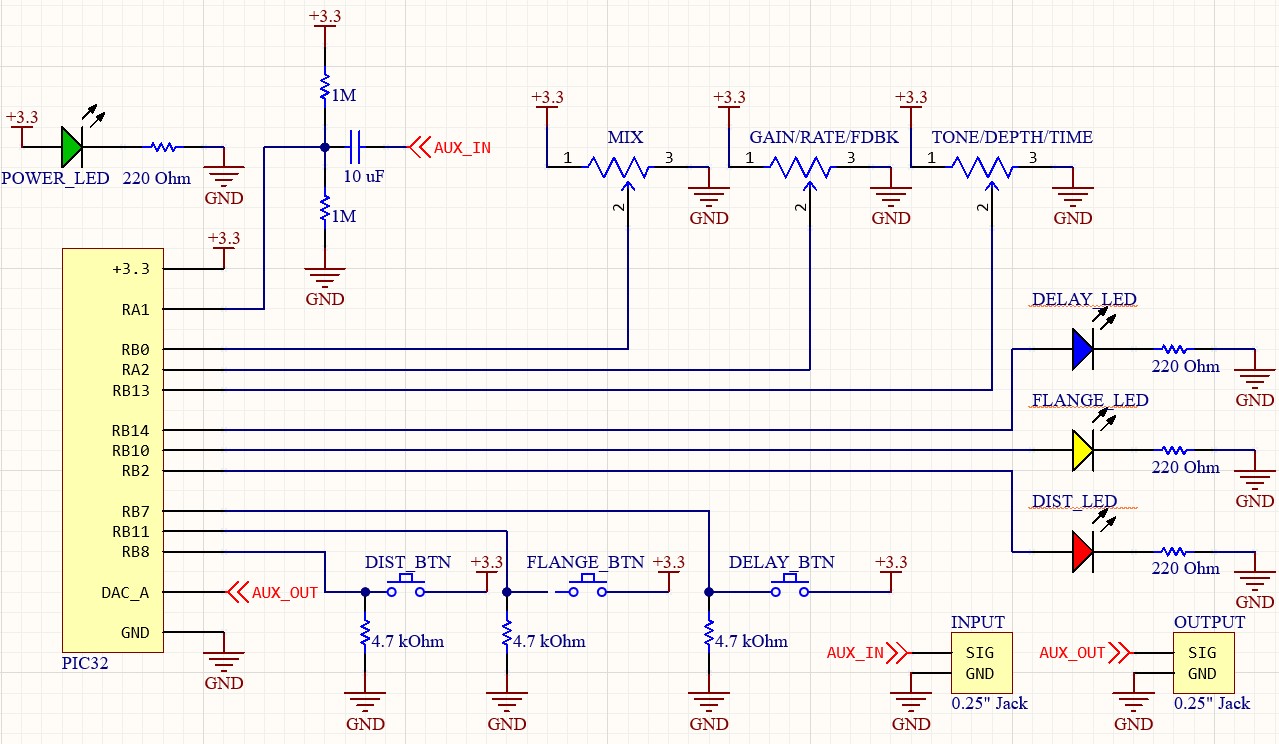
The circuitry implemented inside of the guitar pedal was quite simple, since most of the audio manipulation was done digitally on the PIC. The input signal was acquired through a standard ¼ inch jack (see Appendix C for digikey product numbers, cost, and purchasing links) and passed through a biased high-pass filter to bring the signal into the ADC’s range of operation. In the high-pass filter, the signal was passed through a 10 μF capacitor, the output of which was connected to GND and VDD via two parallel 1MΩ resistors. The resistor and capacitor values were selected to ensure a sufficiently low corner so that any DC bias from the guitar pickups would be removed while preserving the audible signal; since human hearing ranges from approximately 20 Hz to 20kHz, we selected a corner frequency of approx. 1 Hz (cutoff freq = 2*pi/RC = 2*3.14/[10uF * 500 kΩ] = 1.25) to allow audible frequencies to pass through while still blocking DC from the guitar pickup. The equal parallel resistors bias the signal to VDD/2 = 1.65V so that the ADC can detect the signal, since it cannot measure negative voltages. The output of the biased high-pass filter is then passed to the ADC input (pin RA1) on the PIC.
After the signal is digitally processed on the PIC, it is converted to an analog output via the 12-bit DAC on the development board. The DAC output is directly sent to the output ¼ inch jack of the guitar pedal, which can be connected to an external speaker for amplification and sound production.
To allow the user to switch between different effects, three large arcade-style buttons (generously provided by Andrew Tsai) are mounted on the pedal box. Each button is mechanically connected to a limit switch (Digikey #SS-5GL2) so that the switch is closed when the button is pressed. The terminals of each switch are wired from a GPIO pin on the PIC to GND, and a 4.7 kΩ resistor serves as a pull-down connection to GNDto prevent the node from floating when the switch is open; in this setup, the GPIO pin reads high when the button is pressed and reads low when the user is not interacting with the button.
The three knobs used to control different effect parameters are simply 1 kΩ potentiometers with outputs that range from VDD to GND. A low-resistance potentiometer was selected to prevent the potentiometer from forming a voltage divider with the high input impedance of the ADC. The output pin of each potentiometer is connected to an analog input pin on the PIC. The three LEDs used to indicate the current effect are each wired from a GPIO pin to GND, with a 220Ω resistor to limit current drawn from the PIC. The power LED in the top right corner of the pedal is connected from VDD to GND, also with a 220Ω current-limiting resistor. Please see Appendix B for a schematic of the internal circuitry.
Hardware Testing and Debugging
Testing was done throughout the project with an online virtual guitar which was connected to the ADC using an AUX cable to the computer. We faced some challenges when it was time to test the code with a guitar connected to the ADC with a quarter inch jack. We did not get any output when the guitar was being played. The guitar was producing a signal but was not being sent to the ADC. We knew there was an input signal because the probes of the oscilloscope were connected to the input. Our setup was as follows: The quarter inch jack of the guitar was connected to the microcontroller via a breadboard with a biased high pass filter. This allowed us to increase the DC bias on the signal to prevent the ADC from zeroing the negative part of the waveform. A 0.1µF capacitor was initially used in series with two parallel 1kΩ resistors — one connected to ground, the other Vdd. However, this posed an issue where the cutoff frequency of the high-pass filter was very high and attenuated the entire input signal. The fix was to further increase the resistance to 1MΩ to lower the high-pass corner and prevent our audio signal (20 Hz - 20 kHz) from being filtered out. Initially, we had also thought that an amplification stage would be needed before the ADC input because the signal amplitude would be too low for the ADC to properly capture, but we found that the output from the guitar was loud enough to faithfully reproduce using our system
Software Details
Software Structure
The sampling of the input audio and computation of the output signal is performed inside of an interrupt service routine (ISR) that fires 44,000 times per second; the activation of this ISR is tied to the overflow of the Timer2 counter on the PIC32, which resets to zero every time the timer counts past sys_clock/44,000. In the ISR, we read the ADC to get an input audio sample, then apply an effect based on which button is pressed. The ADC reading is then stored in an array for the delay and flanger effects, and the computed output signal is then sent to the DAC over SPI.
Polling of the button and potentiometer states is performed using two protothreads (one for the buttons, one for the potentiometers) that execute every 100 ms. In the button protothread, the PIC simply reads the state of each button using the mPortBReadBits command; we use if..else if statements to ensure that only one effect is active at any given time, even if multiple buttons read high. In this thread, we also call a function that illuminates an LED based on the button states. In the potentiometer thread, we read the ADC values for each of the potentiometers and compute the parameters for each effect (e.g., distortion gain, delay time, etc.) based on the potentiometer state.
In main, we initialize Timer2 for the ISR and set up system-wide interrupts. We also define input pins for the buttons, potentiometers, and input audio, and set up output pins for the LEDs and DAC control select line. We also compute sine table values for the flanger effect and set up the ADC to automatically scan and record channels corresponding to the three potentiometers and input audio pin. Here, we also initialize the protothreads used in our program.
Bypass Effect
Our system starts in bypass mode, where the input audio signal recorded by the ADC is sent directly to the DAC without any modification. Upon pressing a button, the pedal applies one of three effects, described below:
Distortion Effect
Internally, the distortion effect has two parts; we first must distort the signal, then apply the low pass filter. To create the distorted effect, we first must amplify the original signal. If it were centered at 0, we could simply multiply it by the gain value, but because we had to bias the input so the ADC could read it, we must first translate the signal to be centered at 0 before multiplying it, and then returning it to its original midpoint. To find this middle value, we hand tuned a constant that we used to shift the signal, ensuring that the output would generally be correctly clipped on both the top and bottom of the waveform. Initially, we had tried to compute a running average of the input audio signal to estimate the value about which the signal oscillates, but we found this method to be unreliable; the average computed by the PIC was slow and did not accurately generate the midpoint of the signal, perhaps because the number of samples able to be stored in memory was insufficient. Once we had this constant, we could then shift the input signal, then clamp the value so that its absolute value never exceeded the threshold. We then shifted the signal back to its original position. With no low passing, the signal is modified like so:
distortion[n] = clamp(in[n] - BIAS * gain, -THRESHOLD, THRESHOLD) + BIAS
To remove the sharp-sounding high frequency components from the distorted signal, we applied a low pass filter with a corner frequency tunable by the “Tone” knob on the pedal. To efficiently apply a digital low pass filter to the output signal, we implemented a recursive IIR filter of the following form:
omega = cutoff_freq * sample_time; alpha = omega / (1 + omega);
effect_out = distortion[n] * alpha + (1 - alpha) * signal_out;
As the cutoff frequency increases, the value of alpha approaches 1 and the output signal increasingly depends on the current signal input, allowing more high-frequency content to pass through to the output. Conversely, as the cutoff frequency decreases, alpha approaches 0 and less of the current input is considered (essentially averaging over more past values), creating a low-pass effect.
Delay Effect
For our delay effect, we must store the audio samples we read in to be able to then add them to the output a moment later. A large array stores the samples from approximately the previous quarter second. Instead of rewriting the entire array with every new sample, we simply keep track of where in the array we are looking, and rewrite that oldest value, continually cycling through the array. To add the delayed signal, we simply have to calculate how many samples back to look to find the old sample, and then add it to the new output.
target_idx = current_array_idx - DELAY
if (target_idx < 0) target_idx += array_size
Where DELAY is set by the delay time knob. We also only use a delay if we have recorded samples from the previous quarter second, so we don’t add uninitialized values to the output.
With no feedback, the effect will look like this: effect_out[n] = in[n] + in[n - delay_time]
Taking feedback into account, we get a slightly more complicated statement:
saved[n] = in[n] + feedback * saved[n - delay_time]; effect_out[n] = in[n] + saved[n - delay_time]
We then have to divide the output by 1 + feedback to ensure that as the feedback is turned up, the output amplitude doesn’t simply increase. Otherwise, the amplitude may become greater than the DAC output value, which would create significant unpleasant distortion. Additionally, if the delay time changes suddenly, because there are only 256 values of the potentiometer (after we low pass it) but up to around 11,000 samples, small changes in the knob value for delay time can mean that the delayed audio will skip around and potentially have audio artifacts from the audio changing in a non-smooth way. While the low pass filter on the knob mostly stopped this, it still happens significantly when the delay time knob is purposely changed. To help mitigate these unwanted artifacts, we created an averager for the delay time. It saves the last 8 values of the delay time and averages them together (recall that the knob is sampled 10 times per second). This helps ensure that the delay time changes smoothly. One tradeoff is that because we average the delay time over a number of samples, when a user adjusts this knob, it won’t immediately get to the value specified.
Flanger Effect
Because a flanger is built on a delay pedal, we use the same internal infrastructure (sample array, indexing variables, etc…) to create this effect. But on top of the delay, we create a sine table with 256 values to create our LFO. Then, we keep track of where we are within this table and increment the index of the sine table based on the target period using the rate parameter:
sine_idx++ sample = 0; }if (sample >= rate * SAMPLE_FREQ / SINE_TABLE_SIZE) {
This ensures that we iterate through the full sine table every rate seconds. Then, we adjusted the how far back in the delay we look based on the value of the sine table and the delay depth:
delay_diff = BASE_DELAY + (depth * BASE_DELAY * sine_table[sine_idx])
This results in an effect that is generally described by:
effect_out[n] = in[n] + in[n - (DEFAULT_DELAY + depth * sin(rate * n))]
In the pseudocode above, note that there is a default delay of around 15 milliseconds around which the oscillation occurs. The following shows this more clearly:
effect_out[n] = in[n] + in[n - delay]delay = DEFAULT_DELAY + depth * sin(rate * n);
Design Results
Mix Parameter
While the mix knob is used for each effect, the way it works for the delay effect internally is different. This is because both distortion and flanger are effects in which the tone of the signal is altered. For these ones, we want the mix knob to help switch between the dry signal and the wet signal, so the mix knob turned all the way up will only output the altered sound:
out[n] = mix * effect_out[n] + (1 - mix) * in[n]
A delay effect, on the other hand, generally adds (an echo) to the original sound. If the mix worked the same way as the other effects, then the mix knob turned all the way up would simply delay the input as if there were latency in the signal chain, which is generally not a desirable effect. Instead, with the mix all the way up, we still want to hear the original sound as well:
out[n] = mix * effect_out[n] + in[n]
Interfacing with Hardware
Besides calculating the actual effects, this pedal also required interfacing with various external inputs and outputs, including the DAC, various analog inputs, the three buttons, and the LEDS. We read from the ADC as an analog in, as we do for each of the three knobs, to get a value between 0 and 1023. We sample the ADC in an interrupt that is called at 44.1 kHz. This is a standard value often used in the audio industry, but it also ensures that we can sample frequencies above 20 kHz (by the Shannon Nyquist Theorem), which is often considered the upper limit of human hearing. Meanwhile, we sample the knobs 10 times a second, because we don’t want to be updating their value as often, and we then right-shift each potentiometer value by 2 bits, converting them from 10 bit to 8 bit values, but essentially low passing them so the noise doesn’t constantly change effect parameters and potentially disrupt the sound. To write the new sample to the DAC, we communicate over an SPI channel.
Each of the buttons and LEDs that are associated with an effect are connected to digital pins; the buttons are connected to digital-ins, while the LEDs are connected to digital-outs. The buttons are not latching, so we created a toggle system: When a button is released, if that effect is active, we deactivate it and turn off the LED; otherwise, we deactivate all other effects and activate that one. Then, we set the corresponding LED to be on and all others to be off. This ensures that only up to one effect and LED are on at a time. Similar to the analog ins, this is also done in an interrupt that occurs every 100 ms. (Note that the green LED is always on when the device is powered on, so it is only powered by the board, but not controlled in software.
Delay Results
Our pedal was able to successfully implement the Delay, Flanger, and Distortion effects described above; each of these effects are analyzed and demonstrated in the sections below. See Appendix G for fun videos and a link to our full demo video!
Delay Videos
The video below demonstrates changing the “Delay Time” parameter, which adjusts how long after the original sound until the delay is played:
The video below demonstrates changing the “Feedback” parameter, which adjusts how much of the delayed signal is fed back into the effect:
The video below illustrates the delay copies appearing on an oscilloscope as the effect is played:
Scope Outputs
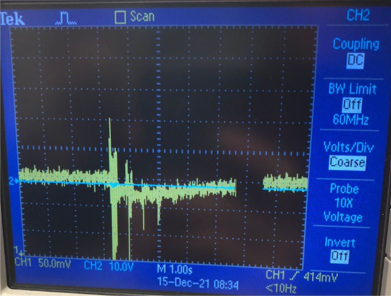
The delay effect copies a signal, potentially multiple times if the feedback is high. The following oscilloscope output shows the original signal along with the copy immediately following it:
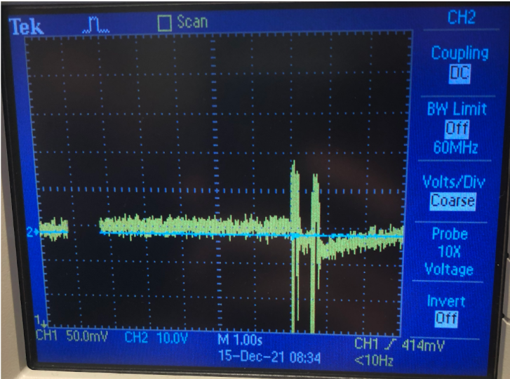
The picture below shows the same effect with a lower mix. While the initial sound is played at the same volume, the copy is relatively quieter. The user therefore can choose how much “wet” effect sound they want mixed into their “dry” clean signal.
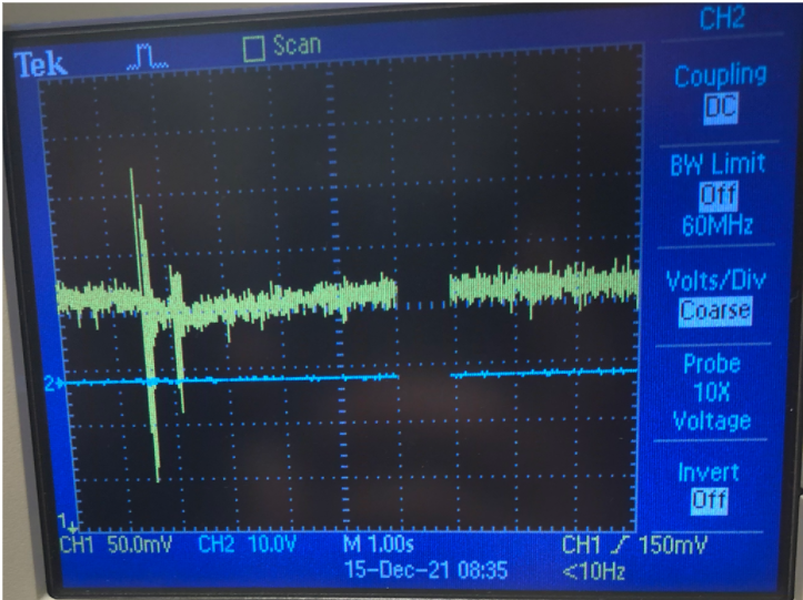
The feedback option causes the delayed signal to be fed back into effect, resulting in continued repetitions of the original signal. The image below shows the delay effect in action with feedback turned up, as viewed on an oscilloscope. Note how the copies continue to decrease in volume; this was done in order to prevent delays from continuing indefinitely (and quickly becoming too loud as any new sounds stacked on top of each other):
Flanger Results
Noise in the oscilloscope readings and degradation of the signal over time due to damping effects prevented the flanger effect from being clearly visile on the scope, so images of scope outputs are not included. However, the effect is quite audible, as shown in the videos below:
Videos
The video below demonstrates changing the “Rate” parameter, which adjusts the speed of the flanger’s low frequency oscillator (LFO):
The video below demonstrates changing the “Depth” parameter, which adjusts how much the LFO changes the delay time:
Distortion Results
Videos
The video below demonstrates changing the “Gain” parameter, which adjusts how much the input signal is amplified and slammed into the threshold:
The video below demonstrates changing the “Tone” parameter, which adjusts the cutoff frequency of the low pass filter applied to the output:
The distortion effect successfully amplifies and clips the input signal; the amplification is especially visible on an oscilloscope, where a more typical looking signal becomes block-shaped when slammed against the clipping threshold. This can be seen in the video below:
Additionally, a more zoomed in version is shown below, where the clipping of the waveform can be more clearly seen. While it isn’t completely flattened against the threshold, it is still pushed relatively hard against that cap, creating many new high pitched harmonics that distort the tone:
Digital Quantization
Because distortions work by multiplying the input signal until the waveform is pushed up against a threshold, the input signal may be greatly magnified. This is done digitally, so when the signal is multiplied, but then capped at a certain frequency, we are essentially reducing how much information we use to store the dynamic range, or the amplitude value at each sample. This can cause the distorted signal to become “quantized” because we now have fewer bits of information to store it, giving it a less pure distorted tone that sounds slightly like a “bitcrusher” effect. This is one of the tradeoffs of doing a multi-effects pedal— while we can easily make the knob control different parameters digitally based on the active effect, we can’t make the knob control an analog input gain because then it would have to apply for each effect, not just the distortion.
Equalization
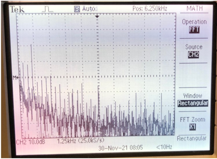
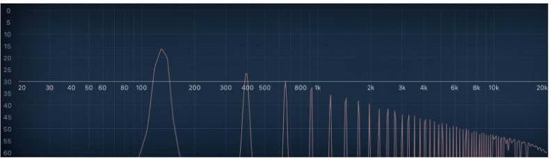
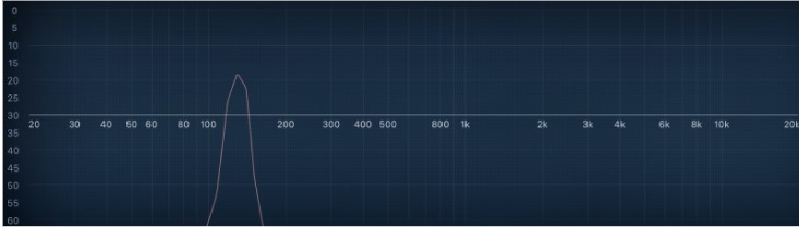
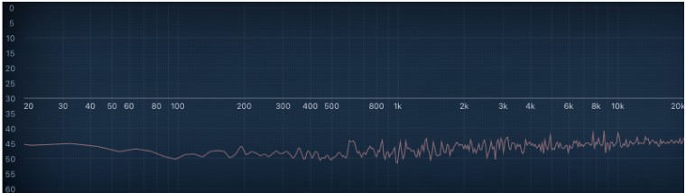
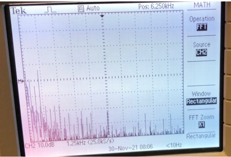
With more and more distortion, especially with high gain levels, waveforms pushed up against the hard limit are capped similar to square waves, and the distorted signal begins to get more of the harsh harmonics that square waves have. See the results section below for more details. Figure 5 shows a spectrogram of a distorted signal coming out of our pedal, and Figure 6 illustrates the harmonics of a pure square wave. While the distorted output has many additional harmonics from the original signal, plus noise that likely comes from the 12-bit DAC, the relative shape of the harmonic patterns are clearly relatively similar. For reference, analyses of a sine wave and white noise are also included in Figures 7 and 8.
Because many of these high frequency harmonics are often unpleasant for the listener, distortion effects usually include a low pass filter, with a cutoff frequency controlled by a knob that’s often labelled, “tone”. This allows users to roll off some of the high frequencies to get a more pleasing tone that suits the user’s needs. A spectrogram of the distortion output with a low pass filter applied is shown in Figure 9.
Other Details
The usability of our pedal was quite intuitive and worked similar to existing guitar pedals available on the market. Safety was ensured by enclosing all of the electronics in a box to prevent any risk of injury from the internal components (e.g., overheating, explosions, sharp wires, shock, etc. - although all of these are very unlikely to begin with). Our pedal uses few analog components and does not emit significant RF noise that can interfere with other designs; the only interference potentially produced by this device are inharmonious sound waves, and the onus is on the user to select the output volume and input audio signals responsibly.
Conclusion
Overall, we really enjoyed working on our project and were able to successfully implement our target of three effects (distortion, flanger, and delay). Each of the three effects can be modulated by the three knobs that set various parameters, and the changes in parameter values are clearly audible, as shown in the videos above. The final enclosure is fairly aesthetic, hides all of the internal wires, and protects the PIC and associated peripherals from the external environment. Our guitar pedal also maximizes ease of use for consumers seeking to use this product in combination with or replacement of existing pedals available on the market; the input and output ¼ inch jacks offer a secure, standardized connection to external audio equipment.
To expand on our pedal, we were thinking of adding a looper effect, which allows users to record long (i.e., 15-20 second) audio samples and mix them into currently played sounds. Because the memory available on the PIC (and the external RAM available in the lab) is quite limited, this would require an SD card to store the large number of audio samples (44000 samples/sec * 15 sec * 2 bytes = 1.32 MB). However, getting the SD card reader to properly interface with the PIC proved to be quite a challenge due to the limited documentation available and time constraints of this project, so we opted to focus on producing more achievable high-quality effects to make this device more useful for consumers. In the future, we could develop an improved framework for interfacing with the SD card over SPI to read and write data. In addition, although all of the effects that we implemented are fully functional, the distortion effect volume is much louder than that of the other effects and pass-through; equalizing volume across all effects would be another avenue for improvement. Future work could also investigate chaining several of our pedals together or activating several effects at the same time; adding a graphical display like the TFT could be interesting as well, but we are quite satisfied with our current design.
Our device does not appear to pose any intellectual property concerns; we did not explicitly reverse-engineer existing guitar pedals, and the methods for generating each effect are general enough that there is no risk of copyright infringement or other IP violations. In principle, our design would be eligible for a patent since the internal design of our pedal (i.e., using a PIC32) is quite different from existing pedals and implements a rather unique set of effects.
Ethical and safety concerns were quite limited for this project. The only feasible hazard posed by this device is the amplification of sound produced by the external speaker, but the onus is on the user to ensure that they do not turn the volume loud enough to sustain damage to hearing. The internal circuitry is completely enclosed in the metal box, so the user is protected from any contact with the electronics or overheating components; because the outside of the box is grounded, the user must take care not to accidentally connect the chassis to a power source. Additionally, if one of the knobs or LEDs comes loose, it may pose a choking hazard, but the risk posed is quite minimal. There are no legal considerations or applicable laws related to this device, with the exception of city noise ordinances, which the user is responsible for abiding by.
Acknowledgements
Many thanks to Hunter Adams and Bruce Land for their guidance on our project and help in the lab. In addition, our project would have been much less aesthetically pleasing without the assistance and material support of Andrew Tsai.
Appendices
Appendix A - Statements
The group approves this report for inclusion on the course website.
The group approves the video for inclusion on the course YouTube channel.
Appendix B - Circuit Schematics
Appendix C - Components and Cost Estimation
A spreadsheet listing the components used in our project and cost estimates can be found at this link. Note that many of the component prices decrease when bought in bulk, so the manufacturing cost of the pedal would be much cheaper if it were to be mass-produced for sale on the market.
Appendix D - Distribution of Work
All three group members contributed equally to the software development and design of the pedal enclosure. We also utilized Google docs and a shared drive to collaborate on reports as well as store all files. All of our code was stored on Github. However, most of the work was completed in the lab. For this report, Kingsley wrote the introduction, Jade worked on the Hardware Design, and Jake wrote the Software Design section.
Appendix E - References
Much of our source code handling PIC setup, peripheral initialization, protothreads, and other low-level functions is adapted from the ECE 4760 SECABB software posted on the course website. The PIC32 and peripheral devices were mounted on the course development board designed by Sean Carroll; schematics and layout can be found on the ECE 4760 course website.
Appendix F - Code
A commented listing of our code can be found at this link.The main file in which our code is written is called 'finalproj.c'
Appendix G - Demo Videos
A Cover of The Eagles' "Hotel California" with our flanger effect applied - note the subtle sinusoidal modulation of the output sound:
A rendition of Radiohead's "Street Spirit" with the delay effect applied:
We're (not) going crazy - an Ozzy Osbourne song distorted by our pedal:
Smells like 4760 - a Nirvana hit showcasing our distortion effect:
Hunter, Play Despacito - a piano rendition of everyone's favorite song with delay and flanger effects applied:
All I Want for Christmas is [4760] - Mariah Carey's classic hit fed into our pedal with fun effects applied! Note that the parameters for the distortion effect were hand-tuned to sound good with the guitar input, which has a slightly different range than the AUX jack from an iPhone, resulting in a slight reduction in sound quality for this effect: