High Level Design 
For our project, we found inspiration through numerous YouTube videos of oscilloscope visualizations of music. We found it fascinating how they could create such interesting and complicated visuals just from two signals, so we wanted to investigate it more. To try it for ourselves, we directly scoped the two channel audio from those YouTube videos to see what they look like and were sold on the idea when we saw the animations on our own oscilloscope.
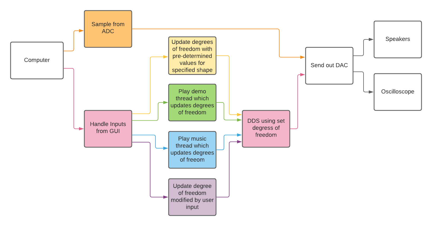
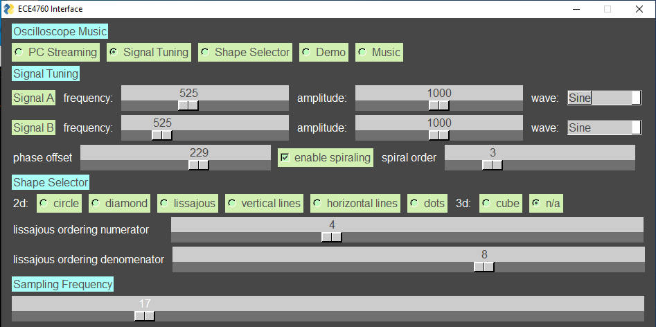
Our final design has a few different modes -- streaming, signal tuning, shape selector, demo, and music -- which can be selected using a python GUI. In each mode, some output is sent through the two DAC outputs to channel 1 and channel 2 of the oscilloscope, displaying the signal as well as to the speaker to play the corresponding sound.
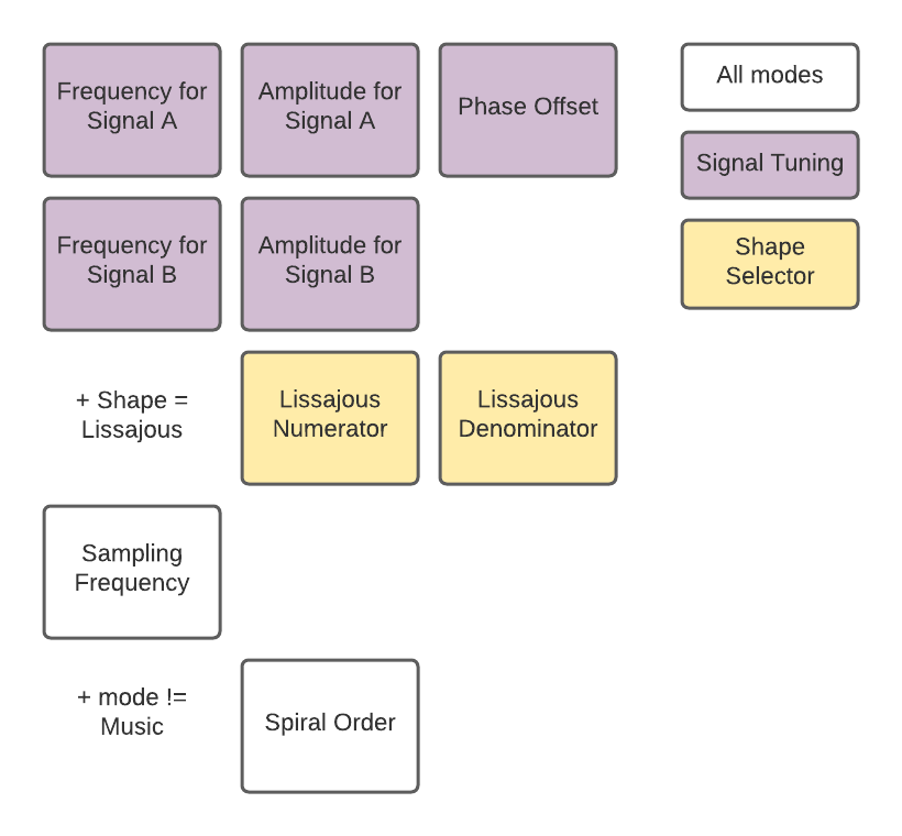
In the streaming mode, the output audio from a computer (or any signal that can be output through a headphone jack) is displayed on the oscilloscope. The two channels from the computer audio are taken in and sampled through the ADC, and then sent through the DAC. Although this is not strictly necessary to view signals on the scope, it keeps the usage of our PIC32 consistent and prevents the user from having to rewire our project when changing between modes. In signal tuning mode, we allow the user to customize the two output signals. The user can change attributes like the shape, frequency, amplitude, spiraling, and relative phase of the two signals to create custom shapes. In shape selector mode, the user can select from a variety of shapes (circle, diamond, lissajous of different orders, horizontal and vertical lines, dots, or a cube). In this mode, the PIC32 controls the GUI, moving and setting the sliders and buttons on the GUI to show how you would get those shapes in the signal tuning mode. Next, we have our demo mode that plays a predetermined visually pleasing sequence on loop. Similarly, the music mode plays the Cornell Alma Mater on loop with visuals on the oscilloscope. Both the demo and music also show the settings of how to generate the images and sounds played. In every mode, we also allow the user to change sampling frequency. The block diagram illustrating these various modes can be seen in the figure below where orange indicates PC streaming, pink indicates the modes besides PC streaming, yellow indicates shape selector, green indicates demo, blue indicates music, purple indicates signal tuning, and white indicates steps that include all of the modes.
Background Math 
One of the main mathematical concepts behind our implementation is direct digital synthesis (DDS) where we can generate a single period of a type of wave in an array (for example, a sine wave) and then sample the different indices of the array in different increments in order to create a resulting wave of a different frequency. Let’s call the value that indexes the array the accumulator. The faster that we increment the accumulator, the faster we move through our array and the fewer samples we take of a single period of the sine wave, resulting in a wave of a higher frequency. If our accumulator increases more slowly, we create a wave of a lower frequency, showing that the value of the increment and the frequency of the wave are linearly related. We use DDS to create our various types of waves since we can create an array of size 256 for a period of each type of wave we want to use (sine, triangle, square, sawtooth), each with an amplitude of 1. Then, to change the frequency, we change the increment value and to change which wave we want to use, we change which array we are sampling from with that increment. This allows us to change the frequency and type of wave degrees of freedom.
To create a relative phase between our signals, we need to calculate a fixed offset that alters our accumulator variable for indexing into our DDS arrays. Since the user can input a phase from 0 - 359 degrees in our GUI, the below math can be used to calculate the correct offset.
float ptsPerPeriod = wave_table_size / (DDS_increment_B >> 25);
int phaseShift = (int)(ptsPerPeriod * relativePhase / 360);
We first obtain how many points we sample in one period of our signal. We then take the user’s input phase and multiply by the points-per-period divided by 360. This maps our phase shift from degrees to array indices, giving us our offset value.
For our shape selector mode, we can generate a few simple 2D shapes. For instance, to generate a circle, we use equal amplitude sine waves in both channels (and thus both axes on the oscilloscope screen), but they have a 90 phase shift between them. This directly follows the parametric equation of a circle: $x = rsin$ and $y = rcos$
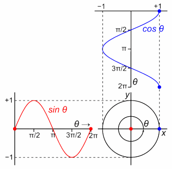
With basic trigonometry, we know that a cosine is just a 90 degrees out of phase sine wave. Additionally, the radius, which corresponds to the amplitudes of the signals sent out of the two DACs, is equal in both signals. And thus, sending a sine to one channel of the oscilloscope and the same wave, but 90 degrees phase shifted to the other channel results in a circle. A similar calculation (using different parametric functions) can be done to show that a diamond (a square rotated by 45 degrees) is generated with two same amplitudes, same frequency, and 90 degrees out of phase triangle waves.
Another figure we allow the user to select and customize in the shape selector mode is a Lissajous curve. A Lissajous curve is a set of parametric equations, both of which are sinusoids, that have different frequencies and potentially different phases: $x = Asin(at + \phi)$ and $y = Bsin(bt + \psi)$
The ratio, $\frac{a}{b}$ highly affects the appearance of the curve. A more “simplified” rational number $\frac{a}{b}$ with a smaller ratio between the number and denominators produces a lissajous with fewer curves. The simplest lissajous would be an ellipse where $\frac{a}{b} = 1$. If the ratio then becomes 2, we get sort of horizontal butterfly wings. The number of “lobes” or loops is directly correlated to the ratio of $\frac{a}{b}$. The simplified form of the rational number indicated the number of “lobes” in that axis. So, using the example of the 2:1 lissajous, we have 2 lobes in the horizontal direction and 1 in the vertical direction.
$\;$
$\;$
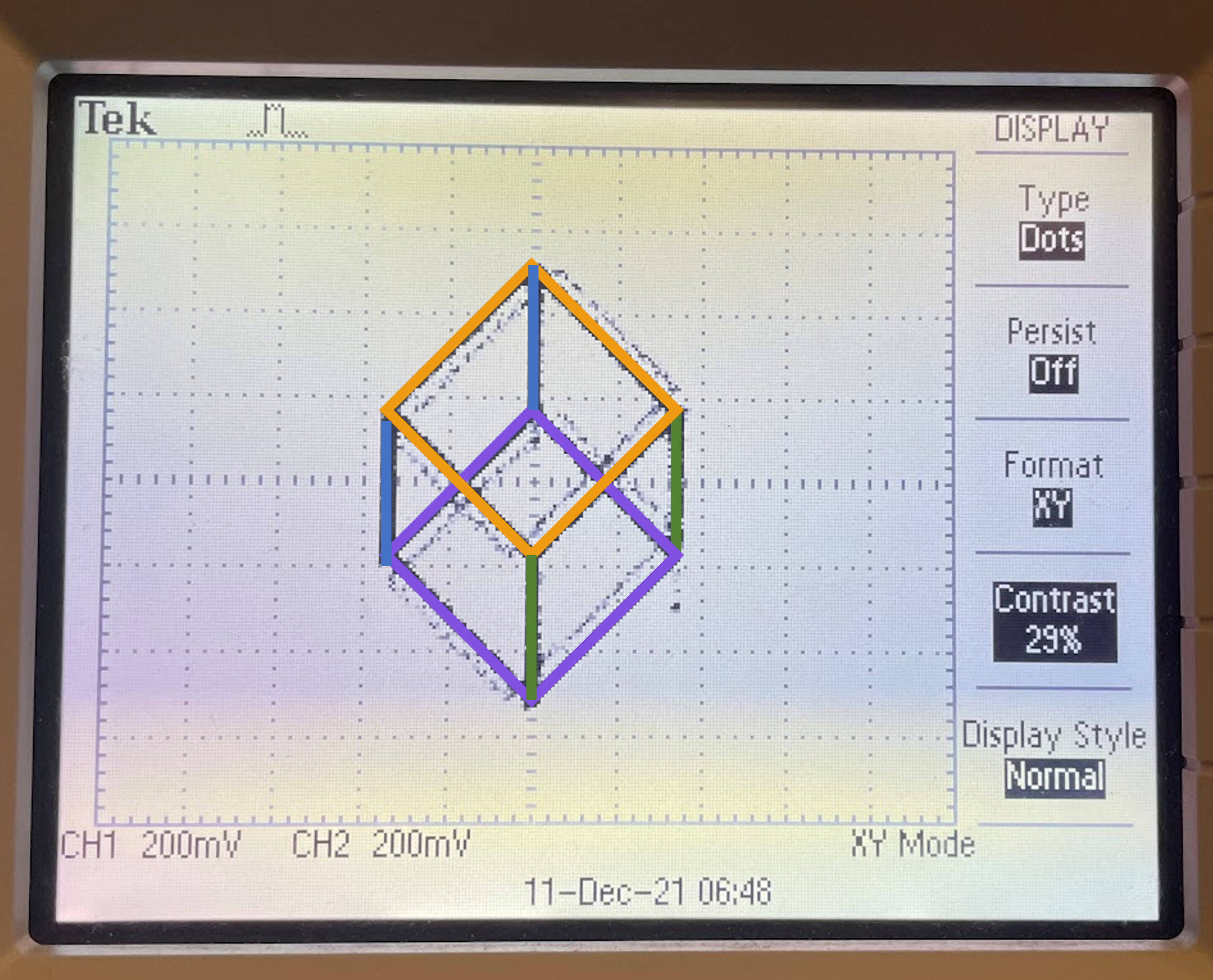
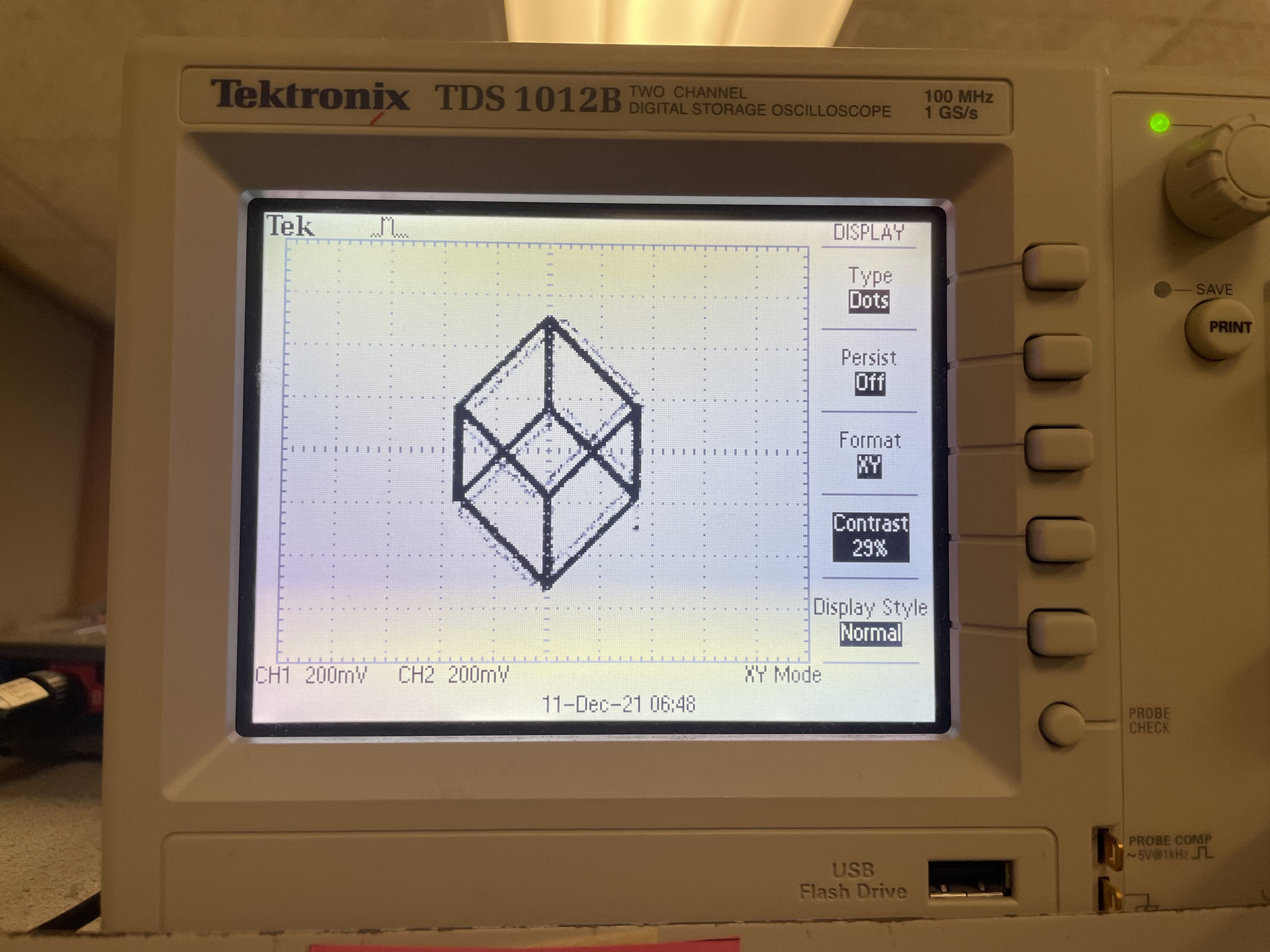
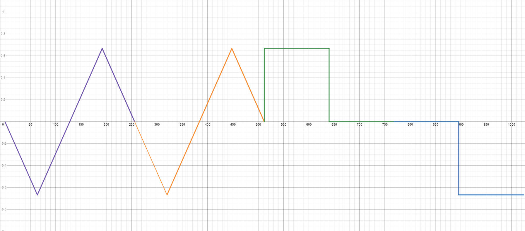
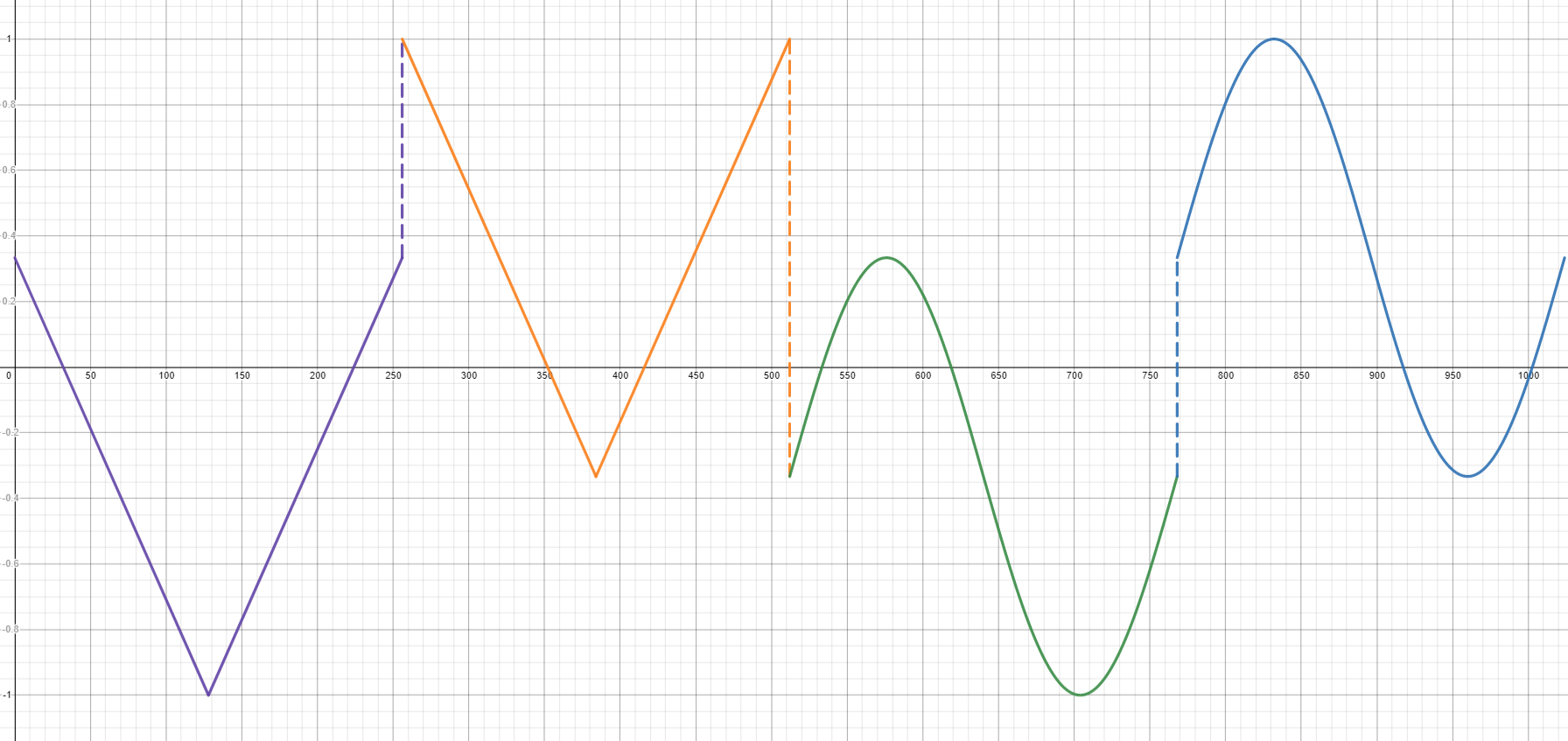
Our GUI also allows the user to view a cube on the scope screen. This is where DDS really displays its usefulness and flexibility. Since we can pre-populate arrays with values corresponding to any signal we desire, we can mix-and-match, creating signals that start out as sine waves, and then jump to square waves, triangles waves, etc. The images of the two cube waves (x and y directions) can be seen below. As shown, we were able to combine a lot of the shapes and waveforms that we had seen already such as a diamond, square wave and sine wave into a single wave that alternates between the shapes so quickly that it is only detected as a single shape on the oscilloscope. Instead of just the 256 entries that the other waves have, our cube table is made up of 1024 entries. Since we know that two 90 degree out of phase triangle waves make a diamond, in the first two sets of 256 entries, we have such triangle waves, but one set is shifted vertically (in the wave the y axis) so that the diamonds are vertically shifted. The upper diamond (orange) has the wave shifted up and the lower diamond (violet) has the wave shifted down. Next, We generate two pairs of vertical lines. The first (from 522 to 768) draws the bottom and right vertical lines (green). The width of the cube is 4/3 and the height 2 (at least in our base calculations for the waves, although the real output amplitude is changed when we do DDS), so we have a step function in x to draw lines at 0 and ⅔ with a down shifted sine wave modulating y so that the lines are shifted down, as opposed to centered. Similarly, for the left most and upper vertical line segments of the cube (blue) we have a step function in x to draw lines at x = -⅔ and x = 0 with a sine wave shifted up in the y axis to shift the two line segments down. The images below show the cube and the corresponding segments that our piece wise waves correspond to labelled by color.
$\;$
 |
 |
 |
 |
 |
 |
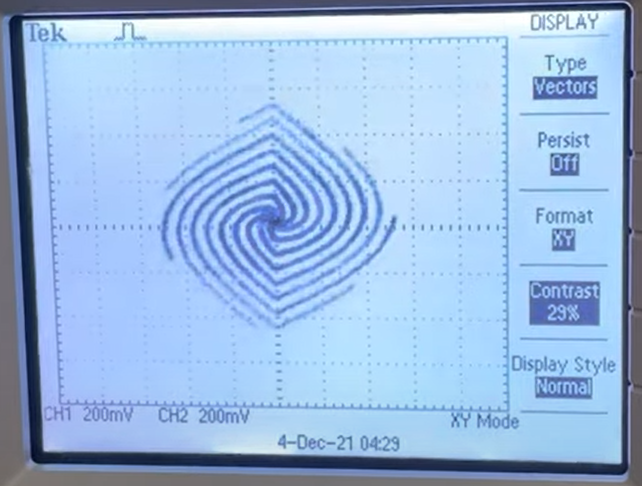 |
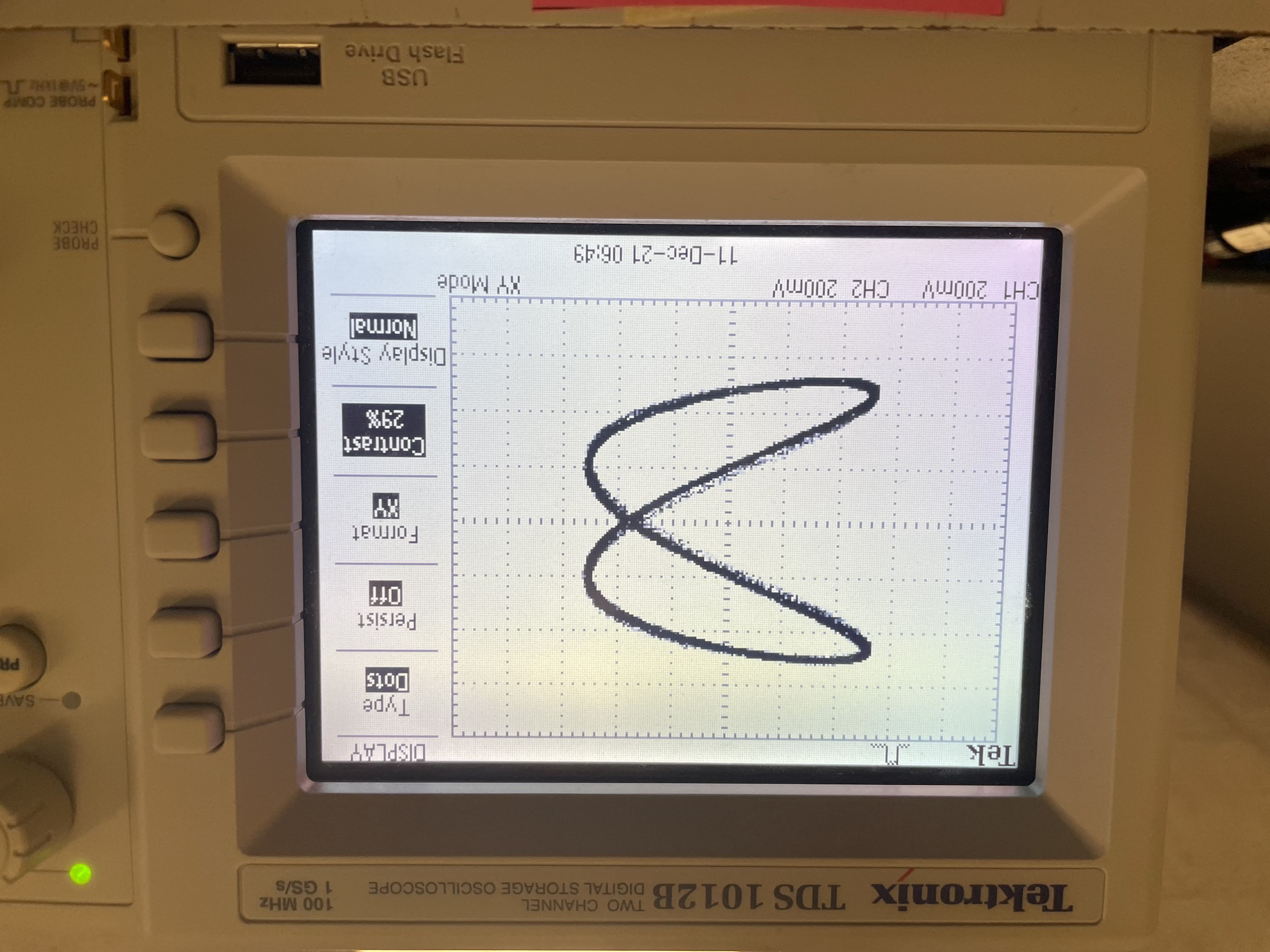
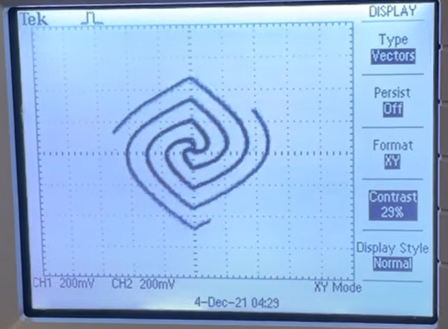
Another cool effect that we can generate is animating the figures displayed. If we modify the frequencies so that it is slightly off, we see an animation that appears to be infinitely looping. With frequencies that are very off, instead of seeing a Lissajous curve, we see animations whose period is the same as the least common multiple of the two frequencies. Especially if the two frequencies are relatively prime, the shape changes with time because differing frequencies mean that different parts of the waves line up at different times. It is almost as if the phase is changing with time.
Besides the visual effects, we also can output the sound of the signal displayed on the screen. The frequency of the wave determines what pitch we hear (and we keep the frequencies allowed well within the human hearing range of about 20 Hz to 20 kHz). For example, a frequency of 440 Hz corresponds to the note A4, and the note C5 is generated with frequency of 523.25 Hz. If we set one channel to 440 Hz and the other ro around 523 Hz, we can hear a simple two note chord. Additionally, the different signals produce different types of sounds. For example, a simple sine wave will be a very clear beep type sound whereas a sawtooth wave has more of a buzzer-like quality.
We also allow changes in audio sample frequency (Fs) for the DDS. The PIC32 has a base 40 MHz clock. To calculate the toggle rate (referred to later as generate period) for the timer (i.e., after how many ticks we need an interrupt), we simply do 40 MHz/Fs.
Logical Structure 
The structure of our project is very straight forward where we have two main code files, the C code which is where we perform all of our calcuations, sample from the ADC, and send to the DAC. Essentially all of the block diagram show above is executed in this file. The details of the structure of this file, including all of the threads and methods that we include is explained below in the program details section. The other file that we have is our python code which is what controls the GUI. This file is also explained more in the program details section.
Hardware/Software Tradeoffs 
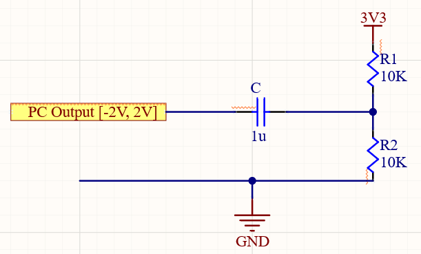
There were some hardware/software trade offs we needed to consider. For example, we needed to decide how we wanted to change the degrees of freedom since we could do it in either a python interface or through actual physical sliders and buttons. We decided to go with the software version since it gave more control on what we could change and update for the interface. In addition, there was also a trade off in allowing the PC streaming mode compared to just using the python interface to control all of the degrees of freedom since it involves more hardware considerations. For example, we needed to add a hardware bypass filter to handle the voltage conversion from the input to the ADC to the output of the DAC. This was needed because the output voltage of the computer is -2V to 2V while the input of the oscilloscope is 0V to 3V.
Because of this, there is a difference in the center of the image from the PC streaming to the image from the other modes in the oscilloscope since there is additional hardware involved with PC streaming for shifting voltages. This is easily remedied on the oscilloscope by changing the x and y position of the center of the image, but it is still an extra step that needs to be taken.
Program/Hardware Design 
Program Details 
On the C side, we are able to receive the messages through the serial thread. When any of the input sliders, buttons, toggles, etc. were moved or pushed/released in the python interface, they would be detected in the serial thread run by the microcontroller which would parse the string it would receive from the python file operating the interface and detect either a slider, radio button, combo (drop down list selector), or toggle change and spawn the corresponding thread.
In the slider thread, once spawned, it would check to see which of the sliders was updated. We utilized a lot of sliders on our interface that controlled various degrees of freedom such as frequency and amplitude for each signal, relative phase offset between the two signals, lissajous numerator and denominator ordering, spiral ordering, and sampling frequency. Based on which slider was changed, it would update the corresponding variable in the C code pending the restrictions based on the current mode the project is in. For example, in PC streaming mode, none of the sliders update the corresponding variables except for the sampling frequency. In addition, the lissajous ordering sliders can’t affect the frequencies unless the mode is shape selector and the current shape is lissajous. A full diagram illustrating which sliders affect the degrees of freedom based on what restrictions can be seen below. While most of the sliders simply update the degree of freedom based on what the slider value is changed to, the sampling frequency is different since it affects the rate of interrupts that we use to both sample front the ADC and send to the DAC. In order to accomplish this update, we close Timer2 which we use to handle our interrupts, calculate the new generate period and update the DDS related values that are dependent on the sampling frequency. We then restart the timer with the new generate period and resume where we left off with all applicable timers and values updated with the new sampling frequency.
$\;$
Our update GUI thread essentially worked reverse to how the above serial threads are described. For our desired functionality, we wanted to ensure that if we were running a specific mode such as the demo or music modes, that the GUI would be able to reflect the current values of the various degrees of freedom that is being played. This allows the user to be able to learn more about the different affects of the degrees of freedom as well be able to change modes in order to modify later. In order to update the GUI properly though, we needed to not only communicate serially from the computer to the PIC32, but also the other way around in order to tell the GUI what values each of the interface blocks should reflect. In this thread, for each degree of freedom, we determine what the current value is, set up a command string to be sent to the GUI that can be parsed at that send, so it needed to communicate what interface block we wanted to change, and what the value should be updated to, and then spawned the serial output thread with our message to send to the computer and thus to the GUI. We had to ensure however that we had our code configured with the correct baud rate (115200) as what we use on the Python side in order to ensure that we could communicate both ways. An example of sending one of our commands to the GUI can be seen below. In this situation, we determine what the phase offset is by taking the value that is stored in relativePhase (which is also the variable that is changed when we change the phase slider), specify what interface block we want to modify (s5, or slider 5 in this example), put them into our specific command format that we parse on the Python side, and then spawn the serial output thread to send the command. We repeat this process for each of the interface blocks.
sprintf(PT_send_buffer, "{s5:%d}\r", (int)(relativePhase));
PT_SPAWN(pt, &pt_output, PutSerialBuffer(&pt_output));
The most important aspect of our C code however, is the interrupt service routine that handles all of our DDS calculations, DAC sampling, and sending to the DAC. We first check to see if we are in PC streaming mode by looking at our mode enum variable. If we are in streaming mode, then all we need to do is sample from each ADC input and setting the DAC output to be the exact values that are sampled. Next, we determine what the amplitude values should be by checking our spiral indicator variable to see if spiraling is enabled or not. If it is then we change the amplitude of signal A and B to be a factor of time (using our time variable). This enables us to change the amplitude of the signals every time an interrupt occurs, resulting in the desired spiral affect. However, if it is not enabled, then we keep the current amplitude values. Next is our DDS calculations for signal A where we first increment DDS phase by our increment value (which is determined by our sampling rate and desired frequency value handled in the slider threads) and then determine which wave table we are going to use through looking at the signal A wave type enum variable and choosing. We then set the DAC for signal A to be the amplitude times the sampled value from the applicable wave array (the index being the shifted DDS phase). We repeat this process for signal B except for this signal, we handle the phase offset. We add this to our shifted DDS phase in order to sample the wave at a different location compared to that of signal A. This is because if both signals are of the same frequency, the peak and troughs of the signal should align if they have no relative offset. With a phase shift however, they would still need to have the same DDS increment value since that determines the frequency of the wave, but the offset lets us sample a different location of the wave, letting us maintain the same frequency of the signal, but changing how the signals align. Next, we check if we are in music mode and if we are, we create an amplitude envelope. The purpose of this is to avoid any popping when the sound is being played, creating an overall, better sounding song. This involves increasing the amplitude of the note at the start and maintaining the set amplitude until we need to decrement the amplitude of the signals at the end of the note. A diagram of how this amplitude envelope works can be seen below which is from our first lab of the semester. After all these calculations are complete, no matter the mode, we increment the note time, increment our time variable based on the current time increment value (which is determined by the slider controlling spiral ordering), and then send the output DAC values to the DAC, creating our visualizations on the oscilloscope, and playing them on the speaker.
$\;$
Not only did we want to show off some interesting visuals that can be made through varying the degrees of freedom of two signals, but we also wanted to show what a song can sound like. In order to do this, we created the music thread that plays Cornell’s alma matter over and over again. Before this thread however, we complete multiple calculations to set global variables relating to our note frequencies and BPM (the song’s tempo). For example, we need to define the frequency of every note which we want to play as well as the duration. Each note is a sinusoidal signal with a specific frequency, and doubling the frequency raises the note an octave. The duration of each note and rest must be calculated in milliseconds and is based on the song's BPM and the smallest subdivision in the song (eight note, sixteenth note, etc). A figure showing the notes in the alma mater along with their frequency can be found below. We also indicate to the GUI thread that it should update accordingly. To create rests, we set the amplitudes to 0 and then yield for the specific amount of time. All these parts come together to create the desired song that we want to play. A video of the music mode on the oscilloscope/spark can be seen in the video below.
$\;$
In order to change what was displayed on the GUI, we had to parse the command that we received as input from the PIC 32 through adding each character one at a time until we reached the end of the command (indicated by \r). Once this string is created, we check to see which input we want to update. For example, if we see an s1, then we want to change slider 1 or if we have c2 then we want to change c2. Based on what we want to change, we take the rest of the command and treat it as what it should be changed to. For the slider 1 for example, we update the value to be what int value the command contains. On the other hand, for c2, we take the string indicating which wave type has been selected and then update that value to be true since that is how we modify a combo type. This is implemented for each of the degrees of freedom that the user and the C side can change in order to show the correct values that are currently being used to create sound on the speaker and visual on the oscilloscope.
Hardware Details 
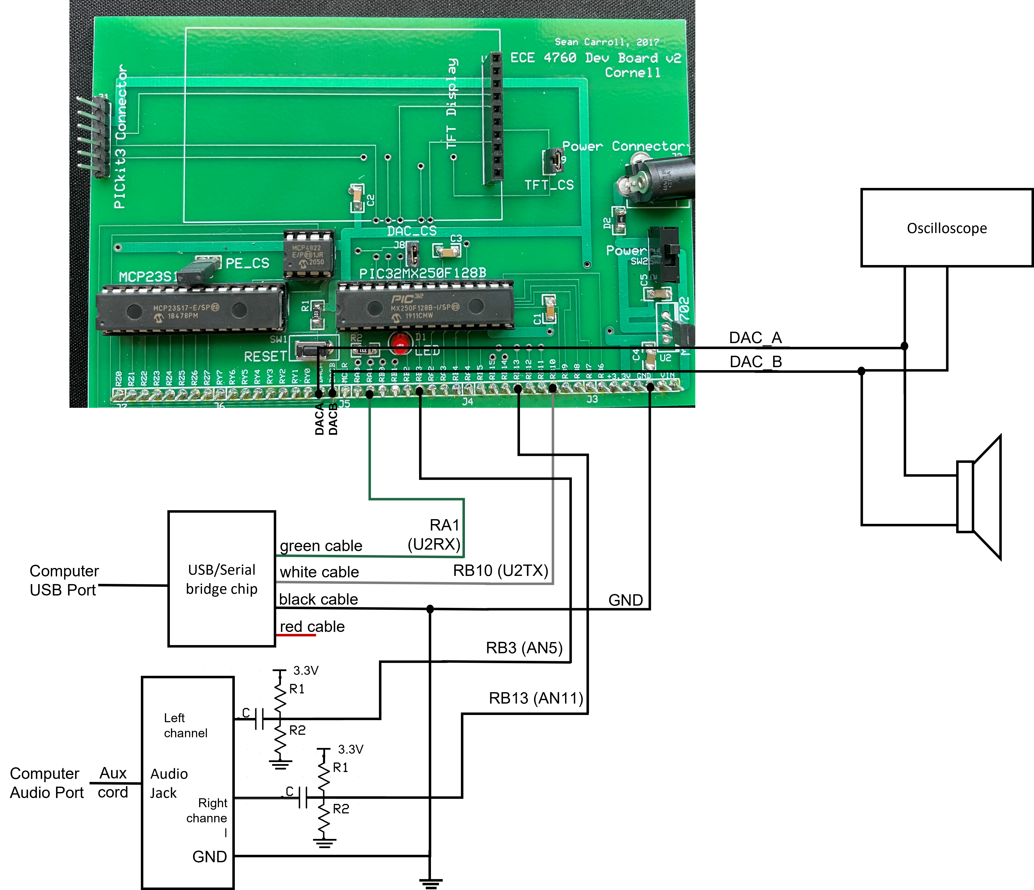
Our project hardware mainly consists of the PIC32 microcontroller and it’s associated breakout PCB from class, from which we heavily utilize the DAC and ADC. One major edition to this is our biased high pass filter. Ideally we would have no filtering, as to allow signals of all frequencies be displayed on the scope. However, when in streaming mode, the signal obtained from the computer’s audio jack ranges from -2V to 2V, but our PIC32 operates with voltages from 0V - 3.3V. Using a biased high-pass filter allows us to shift the computer’s output up. As seen in our schematic below, our filter is a normal high-pass with a pull-up resistor added to our output node. This creates a voltage divider, essentially boosting our signal. With the pull-up resistor tied to 3.3V and the same valued resistors in our voltage divider, the computer audio signal is boosted by 1.65V volts, giving us a range from [-0.35, 3.65]. This is not exactly the PIC32 voltage range, but by limiting the computer volume to 80%, we can ensure that output voltage does not rise above 3.3V. The side-effect however is our high passing filter. This effect was minimized by selecting an extremely low cutoff frequency. With a 1uF capacitor and a 10k resistor, we obtained a cutoff frequency of 16 rad/s which is approximately 2.5 Hz: essentially cutting out DC signals but leaving the rest.
The output of our biased high-pass filter is sampled by the ADC in streaming mode and then passed directly to the DAC. If we are not in streaming mode, the ADC is skipped since we are using DDS and we simply output the calculated values for each channel to DAC-A and DAC-B respectively. These outputs each branch to two wires: one to the speaker and the other to the scope.
Because our project utilizes various pre-calculated values, different protocols, and various threads, we needed to set this all up in our main function. The first task that we complete is to set up interrupts to our default value of 40kHz sampling frequency using Timer2. This is what we use to both sample from the ADC and send the desired output to the DAC. Since the sampling rate is a controllable parameter on our GUI, each time it is changed our timer2 is disabled, reset with the new period and then re-enabled.
In addition, we perform a lot of our initial calculations such as pre-populating our various wave tables (sine, triangle, square, sawtooth), and the cube wave is called as its own separate function from main. We included these calculations in main since DDS merely indexes to a certain value within the array, so if we calculate it once and then reuse the values over and over again, we can save a lot of expensive calculation time involved. This is important since if we add too many calculations to our interrupt, then we could exceed the generate period, therefore breaking our project since the timer is trying to interrupt the interrupt handler. To implement our music demo, we also needed to determine the number of cycles that correspond to a certain type of note, so that we know how many cycles based on the sampling rate we need to yield in order to last that specific duration. Furthermore, in order to facilitate the communication between the computer and the oscilloscope and speakers, we needed to set up the DAC and the ADC where the ADC is set to scan the specific pins that we connect it up to physically on the PIC32. Lastly, we initialize all of the threads that we use to implement our project and schedule them through round robin.
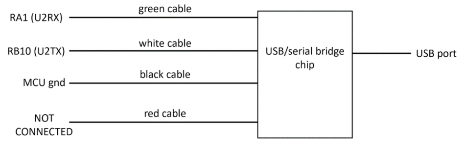
In order to facilitate communication between our microcontroller and the python GUI, we utilize UART/USB serial communication.
Results 
In order to introduce stability in our project, we utilized the GUI and the various restrictions involved as well as the ability to update what we see on it. For example, we described above how the interface can only change specific variables when in certain modes, which helps to prevent the user from changing what frequencies are being played in the middle of the music demo. Restrictions such as this prevent the user from violating the purpose and design of the project in order to ensure the experience of the user is what it’s intended to be. One issue of this however, is that even if a user changes an input on the GUI that doesn’t take effect on the C code, but will still modify the GUI. We work to prevent this from happening through our updating of the GUI thread, including more safety in our design. By doing this, if a user tries to change a degree of freedom when they are in the incorrect mode, they will receive automatic feedback with the GUI resetting to be the current values (not what they incorrectly tried to update). A video of this safety feature can be seen below. This both prevents the user from making changes and thinking that the GUI is broken while also ensuring the safety of the various modes.
On the other hand, all of this updating of the GUI makes it kind of slow. Especially because we have so many inputs to modify all of the various degrees of freedom, the updates take a while and are therefore delayed when we try to do it real time. While this doesn’t make a huge difference in the overall experience when it comes to modes such as PC streaming (since it doesn’t involve the GUI), signal tuning, shape selector, and the demo mode, we did notice a bit of a lag especially in the music mode where the changes occur fairly quickly.
One of the other differences in the results than we intended was through our PC streaming mode. In order to test our functionality, we pulled up some of our inspiration oscilloscope music videos in order to see if we could replicate what they created based on playing that YouTube video. While there were aspects that did look similar, there were some major differences in what we were displaying on our oscilloscope compared to what they had on the video. We believe this is partly due to not being able to separate the channels exactly how they did since we are playing it back through YouTube, which we aren’t sure of how that would affect the sound and which channel it plays out of. We are happy with the results, but wish we had an opportunity to investigate this more because it would have been amazing to replicate oscilloscope music designs just through pulling up a video on a computer. We decided not to include any videos of the differences due to possible copyright infringement since they are videos we found on the internet.
Overall, we feel like our project was a success and are very happy with the results! We were able to support different modes for different features, created a demo that was able to not only show off interesting visualizations, and created a music demo that was able to play a song and show what it looks like. We also took time to ensure the quality of our work such as introducing the amplitude envelope for the music mode in order to avoid the popping noise when changing notes as well as facilitated communication back to the GUI in order to teach the user the effects the degrees of freedom have on the sounds and visuals. In addition, we ensured that our shapes looked like what was advertised and that we kept each of the modes isolated, so that they didn’t affect one another. Not only that though, but we also created a project that anyone could get lost in playing with and enjoying. Our full demo video can be seen below.
One aspect of our project that we love is its usability. The goal of the project is to be able to visualize sounds as well as hear visualizations, which makes it an interesting project that can be used by many types of people. For example, this project could present someone who is deaf the opportunity to see what a song sounds like such as the Cornell alma matter in our music demo. It also allows someone who is blind to hear what different shapes or visualizations sound like such as a circle or a cube or a spiral. The only downside to this project regarding its usability is the interface, so if someone is not able to see the settings or is unable to use a mouse, then they won’t necessarily be able to change the degrees of freedom, but the potential of its usability for people with disabilities is immense and one of our favorite aspects about this project.
Conclusions 
Our project actually differed from our proposal by a bit. This is because initially we were worried about not having enough complexity or challenge if we just used the oscilloscope as a display, so we had added in the TFT as part of our project where we would display our image on both the oscilloscope and the TFT where we believed would have have more creative freedom on the TFT. After starting this project though, we realized that we had plenty of creative freedom from the oscilloscope and decided to focus on that as our primary display, especially because this project is called oscilloscope music after all. After that decision was made, we created new expectations for ourselves which included PC streaming, shape selector (both 2D and 3D), and creating interesting visualizations as well as music. With these expectations in mind, we can say that we definitely met them and even added additional functionality that we had never imagined we would pursue or be able to accomplish such as enabling spiraling, changing as many degrees of freedom as we did such as lissajous ordering, and being able to update the GUI from our microcontroller to display the current values.
We definitely have plenty of ideas on how we could expand on this project in the future. Honestly, we could have spent many more months working on this project because we didn’t want to stop. Some of our ideas include working to reduce more noise especially when it comes to PC streaming. Sometimes, our images on the oscilloscope can seem a bit fuzzy which is why we have the contrast so high, so that it is easier to make out the exact shape. So it would be interesting to investigate that more as well as work to reduce it. Also, it would be beneficial to figure out how to shift the center of the PC streaming mode image on the oscilloscope to match that of the other modes, so the user doesn’t need to change any settings of the oscilloscope while running the project. In addition, our code is not the most optimized and most of our code actually comes from hard coding all of the different degrees of freedom from the music thread. If we did this again, we would work to ensure all of our floating point math is done through fixed point arithmetic instead. In addition, we would create arrays that we could loop through for the demo and music modes in order to reduce code duplication. Regarding expanding the project though, we think it would be interesting to create more 3D shapes since we really enjoyed the math behind making a cube, add the ability to rotate a shape and a corresponding the slider, maybe use the TFT display instead since we could create blue and red lines and put on 3D glasses to see our shapes and animations come to life, more animation style visualizations, and many more. We also wanted to implement a button on the GUI allowing the user to switch which signal was sent to which channel of the oscilloscope. We intended to use a 2:1 mux, however muxes are inherently digital logic blocks, which do not work well when we are trying to select between two analog signals. Buying a mux specifically for this purpose could be a future addition. This project was extremely enjoyable, and there is so much room to expand on it!
Decisions behind our project had two main goals: to allow the user to better be able to explore the relationship between the degrees of freedom of signals, what it looks like, and what it sounds like as well as to allow the user to be able to interact with the interface more easily. This upholds the IEEE standards of ethics since our decisions were made to avoid injuring others, avoid conflicts of interest, avoid any form of harassment, and to treat all people fairly. In addition, we also sought feedback throughout the project, and were willing to admit our errors and room for improvement for the project which was discussed in this webpage.
There are some intellectual property considerations to our project however. For example, we gained our inspiration from various videos we found on the internet, so while it is not reverse engineering design, the overall premise of our project is something that has been done before, although we took it in a very different direction through our use of the GUI to change the degrees of freedom as well as the various modes. In addition, we do use the Cornell alma mater in our project which is intellectual property of Cornell University. Lastly, with PC streaming comes various intellectual property concerns due to copyright since the user can play different videos from the internet which if it is shared online somewhere, could be a violation of copyright which is also a legal consideration to keep in mind when using this project.
Thanks for coming to our TED talk
The Awesome Group
Apendix 
Apendix A - Approvals 
The group approves this report for inclusion on the course website
The group approves the video for inlcusion on the course youtube channel
Appendix B - Schematic 
Appendix C - Bill of Materials 
We obtained all of our necessary materials through what was already provided in the ECE 4760 lab and didn’t need to order any external hardware or materials for our project to function as desired.
- Big Board \$10
- jumper cables \$0.10 each - x11 - \$1.10
- PIC32MX250F128B \$5
- Lab speakers \$2
- sip or header socket/plug \$0.05 per pin - x(28 + 28 + 8) = \$3.20 - DAC, PIC32, port expander
- MCP4822 DAC - \$3.43
- I/O expander \$5
- Oscilloscope - used one from lab \$0
Appendix D - Task Division 
Samantha Cobado
- Implemented the GUI and the two-way serial communication on both the python and C side
- Helped create the demo thread
- Helped implement the amplitude envelope
- Helped create various shapes for the shape selector
- Helped with the initial setup of the C file including setting up the ADC sampling, sending the signals to DAC, enabling interrupts, etc.
Eric Kahn
- Worked on DDS signal synthesis (different waveforms user can select from)
- Helped create 3D cube visual and related math
- Attempted channel switching using a mux
- Worked on math related visualizing lissajou curves and helped implement them first in the parameter tuning section before we created a lissajou option
- Helped with math for calculating relative phase offset and then added this to the audio ISR
- Implemented sampling rate configuration on the C code side based on input from the GUI
- Implemented the Music demo by finding notes frequencies and calculating appropriate timing based on music BPM, before implementing in a C thread
- Setup the biased high pass filter on our breadboard for audio streaming
Ruby Min
- Helped create demo
- Implemented spiralling
- Helped figure out the math and create the wave tables for the cube
- Helped create shapes for shape selector
- Helped implement the amplitude envelope
- Helped allow for changing sampling frequency
- Helped with initial setup of ADC sampling, DAC output, enabling interrupts, etc.
Appendix E - References 
- DDS - https://people.ece.cornell.edu/land/courses/ece4760/PIC32/DDS/DDS.html
- Lissajous - https://en.wikipedia.org/wiki/Lissajous_curve
- Remote Interfaces - https://people.ece.cornell.edu/land/courses/ece4760/PIC32/index_remote.html
- PIC32 Data Sheet - https://people.ece.cornell.edu/land/courses/ece4760/PIC32/Microchip_stuff/2xx_datasheet.pdf
- PIC32 Details - https://people.ece.cornell.edu/land/courses/ece4760/PIC32_details.html
- Oscilloscope Music Videos (where we got our inspiration from) - https://www.youtube.com/channel/UCECl4aNz5hvuRzW5fgCOHKQ
- ECE 4760 Website (our go to site for any info we need essentially) - https://people.ece.cornell.edu/land/courses/ece4760
Appendix F - C Code 
/*
* File: Oscilloscope Music
* Authors: Samantha Cobado
* Eric Kahn
* Ruby Min
*
* Target PIC: PIC32MX250F128B
*/
////////////////////////////////////
// clock AND protoThreads configure!
#include "config_1_3_2.h"
// threading library
#include "pt_cornell_1_3_2_python.h"
////////////////////////////////////
// graphics libraries
#include "tft_master.h"
#include "tft_gfx.h"
// need for rand function
#include <stdlib.h>
//need for sine function
#include <math.h>
//music BPM and notes
#define BPM 90
#define C4 523.25
#define D4_flat 554.37
#define E4_flat 622.26
#define E4 659.26
#define F4 698.46
#define G4 784.0
#define A4_flat 830.6
#define B4_flat 932.32
#define C5 1046.5
#define D5_flat 1108.74
////////////////////////////////////
//milliseconds per each note based on BPM
float msPerEighth= 30000/BPM;
//"not constant" errors here if I use the variable msPerEighth :(
int eighth= (int) (30000/BPM);
int quarter= (int) (2*30000/BPM);
int dottedQuarter= (int) (3*30000/BPM);
int half= (int) (4*30000/BPM);
int dottedHalf= (int) (6*30000/BPM);
int whole= (int) (8*30000/BPM);
int generate_period = 1000;
// cycles for each note based on BPM
int eighth_cycles;
int quarter_cycles;
int dottedQuarter_cycles;
int half_cycles;
int dottedHalf_cycles;
int whole_cycles;
volatile unsigned int DAC_data_A, DAC_data_B; // output values
// === outputs from python handler =============================================
// signals from the python handler thread to other threads
// These will be used with the prototreads PT_YIELD_UNTIL(pt, condition);
// to act as semaphores to the processing threads
char new_radio = 0;
char new_slider = 0;
char new_combo = 0;
char new_toggle = 0;
// current radio-group ID and button-member ID
char radio_group_id, radio_member_id;
// current slider
int slider_id;
float slider_value;
// current combo
int combo_id, combo_value;
// current toggle
char toggle_id, toggle_value ;
// mode enum
typedef enum
{
STREAM = 0,
DDS = 1,
SHAPES = 2,
DEMO = 3,
MUSIC = 4
} mode_e;
mode_e mode = STREAM;
// wave type enum
typedef enum
{
SINE = 0,
SQUARE = 1,
TRIANGLE = 2,
SAW = 3,
CUBE = 4
} wave_e;
wave_e shape_A = SINE;
wave_e shape_B = SINE;
// shape enum
typedef enum
{
CIRCLE = 0,
S_SQUARE = 1,
DIAMOND = 2,
LISSAJOUS = 3,
V_LINES = 4,
H_LINES = 5,
DOTS = 6,
S_CUBE = 7,
NONE = 8
} shapes_e;
shapes_e shape = NONE;
////////////////////////////////////
// Audio DAC ISR
// A-channel, 1x, active
#define DAC_config_chan_A 0b0011000000000000
// B-channel, 1x, active
#define DAC_config_chan_B 0b1011000000000000
//
//// audio sample frequency
//#define Fs 44000.0
//// need this constant for setting DDS frequency
//#define two32 4294967296.0 // 2^32
//// sine lookup table for DDS
//#define wave_table_size 256
//volatile _Accum sine_table[wave_table_size] ;
//// phase accumulator for DDS
//volatile unsigned int DDS_phase ;
//// phase increment to set the frequency DDS_increment = Fout*two32/Fs
//// For A above middle C DDS_increment = = 42949673 = 440.0*two32/Fs
//#define Fout 440.0
//volatile float DDS_increment;
//volatile float DDS_increment_ratio = two32/Fs ;
//volatile float sin_ratio = -3.1415926/5720 ;
//// waveform amplitude
//volatile _Accum max_amplitude=1000;
// need this constant for setting DDS frequency
#define two32 4294967296.0 // 2^32
// lookup tables for DDS
#define wave_table_size 256
volatile _Accum sine_table[wave_table_size];
volatile _Accum tri_wave_table[wave_table_size];
volatile _Accum sq_wave_table[wave_table_size];
volatile _Accum saw_table[wave_table_size];
volatile _Accum cube_table_X[wave_table_size * 4];
volatile _Accum cube_table_Y[wave_table_size * 4];
// phase accumulator for DDS
volatile unsigned int DDS_phase_A = 0;
volatile unsigned int DDS_phase_B = 0;
// DDS variables
volatile int phaseShift = 0;
volatile float DDS_increment_fract = two32 / 44000.0;
volatile int DDS_increment_A = 440 * two32 / 44000.0;
volatile int DDS_increment_B = 440 * two32 / 44000.0;
// waveform amplitude
volatile _Accum max_amplitude = 2000;
volatile int current_amplitude_A = 1000;
volatile int current_amplitude_B = 1000;
// degrees of freedom
volatile int relativePhase = 0;
volatile int update_gui = 0;
volatile unsigned int spiral = 0;
volatile unsigned int time = 0;
volatile int time_increment = 440 * two32 / 44000.0;
volatile int amplitude_A = 1000;
volatile int amplitude_B = 1000;
volatile int lissajous_num = 4;
volatile int lissajous_denom = 8;
// amplitude envelope
volatile int attack_inc = 1, decay_inc = 1;
volatile unsigned int attack_time=1000, decay_time=1000, sustain_time;
volatile unsigned int note_time = 0;
// populates the cube wave lookup tables
void populate_cube_tables()
{
//populate x first
//0-255- trangle
_Accum twoThirds = 0.6667;
_Accum oneThird = 0.3333;
int i;
_Accum yVal = 0.3333; //init value (can set accum this way?)
_Accum triangleSlope = 8.0 / 3.0 / (_Accum)wave_table_size; //0.010417;//x-step= 1 so slope= delta y
int stop1 = wave_table_size >> 1;
for (i = 0; i < stop1; i++)
{
cube_table_X[i] = yVal;
yVal -= triangleSlope;
}
int stop2 = wave_table_size;
for (i = stop1; i < stop2; i++)
{
yVal += triangleSlope;
cube_table_X[i] = yVal;
}
//256-511- triangle shifted up
int stop3 = wave_table_size << 1;
for (i = stop2; i < stop3; i++)
{
cube_table_X[i] = cube_table_X[i - 256] + 0.6667;
}
//512-767
//sin
yVal = -1 * oneThird;
float sinArg = 0;
float sinInc = 2.0 * 3.1415926 / (float)wave_table_size;
int stop4 = 3 * wave_table_size; //2 * wave_table_size + (wave_table_size >> 1);
for (i = stop3; i < stop4; i++)
{
cube_table_X[i] = yVal * twoThirds - oneThird;
sinArg += sinInc; //2pi/wave_table_size
yVal = (_Accum)sin(sinArg);
}
sinArg = 0;
for (i = stop4; i < (4 * wave_table_size); i++)
{
cube_table_X[i] = yVal * twoThirds + oneThird;
sinArg += sinInc;
yVal = (_Accum)sin(sinArg);
}
//populate y
int j;
_Accum yVal2 = 0.0; //init value
//two periods of triangle wave
int stop5 = wave_table_size >> 2;
for (j = 0; j < stop5; j++)
{
cube_table_Y[j] = yVal2;
yVal2 -= triangleSlope;
}
int stop6 = stop5 + (wave_table_size >> 1);
for (j = stop5; j < stop6; j++)
{
yVal2 += triangleSlope;
cube_table_Y[j] = yVal2;
}
int stop7 = stop6 + (wave_table_size >> 1);
for (j = stop6; j < stop7; j++)
{
yVal2 -= triangleSlope;
cube_table_Y[j] = yVal2;
}
int stop8 = stop7 + (wave_table_size >> 1);
for (j = stop7; j < stop8; j++)
{
yVal2 += triangleSlope;
cube_table_Y[j] = yVal2;
}
int stop9 = stop8 + (wave_table_size >> 2);
for (j = stop8; j < stop9; j++)
{
yVal2 -= triangleSlope;
cube_table_Y[j] = yVal2;
}
//square wave: 0.6667 to -0.6667
int stop10 = stop9 + (wave_table_size / 2);
for (j = stop9; j < stop10; j++)
{
cube_table_Y[j] = twoThirds;
}
int stop11 = stop10 + wave_table_size;
for (j = stop10; j < stop11; j++)
{
cube_table_Y[j] = 0;
}
int stop12 = 4 * wave_table_size;
for (j = stop11; j < stop12; j++)
{
cube_table_Y[j] = -1 * twoThirds;
}
}
// === Update GUI Thread =================================================
// sends commands to the python interface to update with the current values
static PT_THREAD(protothread_gui(struct pt *pt))
{
PT_BEGIN(pt);
while (1)
{
PT_YIELD_UNTIL(pt, update_gui == 1);
// change signal A frequency
sprintf(PT_send_buffer, "{s1:%d}\r", (int) DDS_increment_A / (int) DDS_increment_fract);
PT_SPAWN(pt, &pt_output, PutSerialBuffer(&pt_output));
if (mode != MUSIC) {
// change signal A amplitude
sprintf(PT_send_buffer, "{s2:%d}\r", (int)(current_amplitude_A));
PT_SPAWN(pt, &pt_output, PutSerialBuffer(&pt_output));
}
// change signal B frequency
sprintf(PT_send_buffer, "{s3:%d}\r", (int)DDS_increment_B / (int) DDS_increment_fract);
PT_SPAWN(pt, &pt_output, PutSerialBuffer(&pt_output));
if (mode != MUSIC) {
// change signal B amplitude
sprintf(PT_send_buffer, "{s4:%d}\r", (int)(current_amplitude_B));
PT_SPAWN(pt, &pt_output, PutSerialBuffer(&pt_output));
}
// change phase offset
sprintf(PT_send_buffer, "{s5:%d}\r", (int)(relativePhase));
PT_SPAWN(pt, &pt_output, PutSerialBuffer(&pt_output));
// lissajous numerator
sprintf(PT_send_buffer, "{s6:%d}\r", (lissajous_num));
PT_SPAWN(pt, &pt_output, PutSerialBuffer(&pt_output));
// lissajous denomenator
sprintf(PT_send_buffer, "{s7:%d}\r", (lissajous_denom));
PT_SPAWN(pt, &pt_output, PutSerialBuffer(&pt_output));
// change sampling frequency
sprintf(PT_send_buffer, "{s8:%d}\r", (int)(40000.0/generate_period));
PT_SPAWN(pt, &pt_output, PutSerialBuffer(&pt_output));
// change spiral order
sprintf(PT_send_buffer, "{s9:%d}\r", (int)(time_increment / (DDS_increment_fract * 55.0)));
PT_SPAWN(pt, &pt_output, PutSerialBuffer(&pt_output));
// update wave type
if (shape_A == SINE)
{
sprintf(PT_send_buffer, "{c1:Sine}\r");
}
else if (shape_A == SQUARE)
{
sprintf(PT_send_buffer, "{c1:Square}\r");
}
else if (shape_A == TRIANGLE)
{
sprintf(PT_send_buffer, "{c1:Triangle}\r");
}
else if (shape_A == SAW)
{
sprintf(PT_send_buffer, "{c1:Sawtooth}\r");
}
else if (shape_A == CUBE)
{
sprintf(PT_send_buffer, "{c1:Cube}\r");
}
PT_SPAWN(pt, &pt_output, PutSerialBuffer(&pt_output));
if (shape_B == SINE)
{
sprintf(PT_send_buffer, "{c2:Sine}\r");
}
else if (shape_B == SQUARE)
{
sprintf(PT_send_buffer, "{c2:Square}\r");
}
else if (shape_B == TRIANGLE)
{
sprintf(PT_send_buffer, "{c2:Triangle}\r");
}
else if (shape_B == SAW)
{
sprintf(PT_send_buffer, "{c2:Sawtooth}\r");
}
else if (shape_B == CUBE)
{
sprintf(PT_send_buffer, "{c2:Cube}\r");
}
PT_SPAWN(pt, &pt_output, PutSerialBuffer(&pt_output));
// update selected shape
if (shape == CIRCLE)
{
sprintf(PT_send_buffer, "{r2:radio2_1}\r");
}
if (shape == S_SQUARE)
{
sprintf(PT_send_buffer, "{r2:radio2_2}\r");
}
if (shape == DIAMOND)
{
sprintf(PT_send_buffer, "{r2:radio2_3}\r");
}
if (shape == LISSAJOUS)
{
sprintf(PT_send_buffer, "{r2:radio2_4}\r");
}
if (shape == V_LINES)
{
sprintf(PT_send_buffer, "{r2:radio2_5}\r");
}
if (shape == H_LINES)
{
sprintf(PT_send_buffer, "{r2:radio2_6}\r");
}
if (shape == DOTS)
{
sprintf(PT_send_buffer, "{r2:radio2_7}\r");
}
if (shape == S_CUBE)
{
sprintf(PT_send_buffer, "{r2:radio2_8}\r");
}
if (shape == NONE)
{
sprintf(PT_send_buffer, "{r2:radio2_9}\r");
}
PT_SPAWN(pt, &pt_output, PutSerialBuffer(&pt_output));
// change spiral enable
sprintf(PT_send_buffer, "{t1:%d}\r", spiral);
PT_SPAWN(pt, &pt_output, PutSerialBuffer(&pt_output));
update_gui = 0;
}
PT_END(pt);
}
// === Demo Thread =================================================
// run a specific demo sequence to illustrate capabilities
static PT_THREAD(protothread_demo(struct pt *pt))
{
PT_BEGIN(pt);
while (1)
{
// yield until we initiate the sequence
PT_YIELD_UNTIL(pt, mode == DEMO);
// create a circle using the shape selector
spiral = 0;
shape = CIRCLE;
shape_B = SINE;
shape_A = SINE;
current_amplitude_A = 1000;
current_amplitude_B = 1000;
relativePhase = 90;
DDS_increment_A = 440.0 * DDS_increment_fract;
DDS_increment_B = 440.0 * DDS_increment_fract;
DDS_phase_A = 0;
DDS_phase_B = 0;
update_gui = 1;
// wait for 2 seconds
PT_YIELD_UNTIL(pt, mode == DEMO);
PT_YIELD_TIME_msec(2000);
// moving circle with due to difference in frequencies
spiral = 0;
shape = CIRCLE;
shape_B = SINE;
shape_A = SINE;
current_amplitude_A = 1000;
current_amplitude_B = 1000;
relativePhase = 90;
DDS_increment_A = 440.0 * DDS_increment_fract;
DDS_increment_B = 441.0 * DDS_increment_fract;
DDS_phase_A = 0;
DDS_phase_B = 0;
update_gui = 1;
// wait for 2 seconds
PT_YIELD_UNTIL(pt, mode == DEMO);
PT_YIELD_TIME_msec(2000);
// spinning spiral
time_increment = 55.0 * DDS_increment_fract * 9;
spiral = 1;
shape = CIRCLE;
shape_B = SINE;
shape_A = SINE;
current_amplitude_A = 1000;
current_amplitude_B = 1000;
relativePhase = 90;
DDS_increment_A = 441.0 * DDS_increment_fract;
DDS_increment_B = 440.0 * DDS_increment_fract;
DDS_phase_A = 0;
DDS_phase_B = 0;
update_gui = 1;
// wait for 2 seconds
PT_YIELD_UNTIL(pt, mode == DEMO);
PT_YIELD_TIME_msec(2000);
// create a cube using the shape selector
spiral = 0;
shape = S_CUBE;
shape_B = CUBE;
shape_A = CUBE;
current_amplitude_A = 1000;
current_amplitude_B = 1000;
relativePhase = 0;
DDS_increment_A = 440.0 * DDS_increment_fract;
DDS_increment_B = 440.0 * DDS_increment_fract;
DDS_phase_A = 0;
DDS_phase_B = 0;
update_gui = 1;
// wait for 2 seconds
PT_YIELD_UNTIL(pt, mode == DEMO);
PT_YIELD_TIME_msec(2000);
// create a jumpy cube
spiral = 0;
shape = NONE;
shape_B = CUBE;
shape_A = TRIANGLE;
current_amplitude_A = 1000;
current_amplitude_B = 1000;
relativePhase = 0;
DDS_increment_A = 441.0 * DDS_increment_fract;
DDS_increment_B = 440.0 * DDS_increment_fract;
DDS_phase_A = 0;
DDS_phase_B = 0;
update_gui = 1;
// wait for 2 seconds
PT_YIELD_UNTIL(pt, mode == DEMO);
PT_YIELD_TIME_msec(2000);
// create a triangle wave that moves its shape
spiral = 0;
shape = DIAMOND;
shape_B = TRIANGLE;
shape_A = TRIANGLE;
current_amplitude_A = 1000;
current_amplitude_B = 1000;
relativePhase = 45;
DDS_increment_A = 440.0 * DDS_increment_fract;
DDS_increment_B = 441.0 * DDS_increment_fract;
DDS_phase_A = 0;
DDS_phase_B = 0;
update_gui = 1;
// wait for 2 seconds
PT_YIELD_UNTIL(pt, mode == DEMO);
PT_YIELD_TIME_msec(2000);
// create a basic, moving lissajous
spiral = 0;
shape = LISSAJOUS;
shape_B = SINE;
shape_A = SINE;
current_amplitude_A = 1000;
current_amplitude_B = 1000;
relativePhase = 90;
lissajous_num = 4;
lissajous_denom = 8;
DDS_increment_A = 440.0 * DDS_increment_fract;
DDS_increment_B = 881.0 * DDS_increment_fract;
DDS_phase_A = 0;
DDS_phase_B = 0;
update_gui = 1;
// wait for 2 seconds
PT_YIELD_UNTIL(pt, mode == DEMO);
PT_YIELD_TIME_msec(2000);
// create a spiral, moving lissajous
spiral = 1;
time_increment = 55.0 * DDS_increment_fract * 4;
shape = LISSAJOUS;
shape_B = SINE;
shape_A = SINE;
current_amplitude_A = 1000;
current_amplitude_B = 1000;
relativePhase = 90;
lissajous_num = 4;
lissajous_denom = 8;
DDS_increment_A = 440.0 * DDS_increment_fract;
DDS_increment_B = 881.0 * DDS_increment_fract;
DDS_phase_A = 0;
DDS_phase_B = 0;
update_gui = 1;
// wait for 2 seconds
PT_YIELD_UNTIL(pt, mode == DEMO);
PT_YIELD_TIME_msec(2000);
// create a spiral, moving lissajous
spiral = 1;
time_increment = 55.0 * DDS_increment_fract * 6;
shape = LISSAJOUS;
shape_B = SINE;
shape_A = SINE;
current_amplitude_A = 1000;
current_amplitude_B = 1000;
relativePhase = 90;
lissajous_num = 4;
lissajous_denom = 8;
DDS_increment_A = 440.0 * DDS_increment_fract;
DDS_increment_B = 881.0 * DDS_increment_fract;
DDS_phase_A = 0;
DDS_phase_B = 0;
update_gui = 1;
// wait for 2 seconds
PT_YIELD_UNTIL(pt, mode == DEMO);
PT_YIELD_TIME_msec(2000);
// create a lissajous of a 5 / 4 ordering
spiral = 0;
shape = LISSAJOUS;
lissajous_num = 5;
lissajous_denom = 4;
current_amplitude_A = 1000;
current_amplitude_B = 1000;
relativePhase = 90;
DDS_increment_A = 550.0 * DDS_increment_fract;
DDS_increment_B = 440.0 * DDS_increment_fract;
DDS_phase_A = 0;
DDS_phase_B = 0;
update_gui = 1;
// wait for 2 seconds
PT_YIELD_TIME_msec(2000);
} // END WHILE(1)
PT_END(pt);
} // timer thread
// === Music Thread =================================================
// play the alma mater
// add pauses between notes so we don't slur the whole song
static PT_THREAD(protothread_music(struct pt *pt))
{
PT_BEGIN(pt);
while (1)
{
// yield until we initiate the sequence
PT_YIELD_UNTIL(pt, mode == MUSIC);
shape_A= SINE;
shape_B= SINE;
relativePhase= 90;
//Measure 1
DDS_increment_A = A4_flat * DDS_increment_fract;
DDS_increment_B = C4 * DDS_increment_fract;
current_amplitude_A= 0;
current_amplitude_B= 0;
DDS_phase_A = 0;
DDS_phase_B = 0;
update_gui = 1;
note_time = 0;
sustain_time = dottedQuarter_cycles - 2000;
//dotted quarter
PT_YIELD_UNTIL(pt, mode == MUSIC);
PT_YIELD_TIME_msec(dottedQuarter);
shape_A= SINE;
shape_B= SINE;
relativePhase= 90;
//pause
current_amplitude_A= 0;
current_amplitude_B= 0;
PT_YIELD_TIME_msec(33);
DDS_increment_A = B4_flat * DDS_increment_fract;
DDS_increment_B = D4_flat * DDS_increment_fract;
DDS_phase_A = 0;
DDS_phase_B = 0;
update_gui = 1;
note_time = 0;
sustain_time = eighth_cycles - 2000;
PT_YIELD_UNTIL(pt, mode == MUSIC);
PT_YIELD_TIME_msec(eighth);
shape_A= SINE;
shape_B= SINE;
relativePhase= 90;
//pause
current_amplitude_A= 0;
current_amplitude_B= 0;
PT_YIELD_TIME_msec(33);
DDS_increment_A = C5 * DDS_increment_fract;
DDS_increment_B = E4_flat * DDS_increment_fract;
DDS_phase_A = 0;
DDS_phase_B = 0;
update_gui = 1;
note_time = 0;
sustain_time = dottedQuarter_cycles - 2000;
PT_YIELD_UNTIL(pt, mode == MUSIC);
PT_YIELD_TIME_msec(dottedQuarter);
shape_A= SINE;
shape_B= SINE;
relativePhase= 90;
//pause
current_amplitude_A= 0;
current_amplitude_B= 0;
PT_YIELD_TIME_msec(33);
DDS_increment_A = B4_flat * DDS_increment_fract;
DDS_increment_B = D4_flat * DDS_increment_fract;
DDS_phase_A = 0;
DDS_phase_B = 0;
update_gui = 1;
note_time = 0;
sustain_time = eighth_cycles - 2000;
PT_YIELD_UNTIL(pt, mode == MUSIC);
PT_YIELD_TIME_msec(eighth);
shape_A= SINE;
shape_B= SINE;
relativePhase= 90;
//pause
current_amplitude_A= 0;
current_amplitude_B= 0;
PT_YIELD_TIME_msec(33);
//measure 2
DDS_increment_A = A4_flat * DDS_increment_fract;
DDS_increment_B = D4_flat * DDS_increment_fract;
DDS_phase_A = 0;
DDS_phase_B = 0;
update_gui = 1;
note_time = 0;
sustain_time = quarter_cycles - 2000;
PT_YIELD_UNTIL(pt, mode == MUSIC);
PT_YIELD_TIME_msec(quarter);
shape_A= SINE;
shape_B= SINE;
relativePhase= 90;
//pause
current_amplitude_A= 0;
current_amplitude_B= 0;
PT_YIELD_TIME_msec(33);
DDS_increment_A = F4 * DDS_increment_fract;
DDS_increment_B = D4_flat * DDS_increment_fract;
DDS_phase_A = 0;
DDS_phase_B = 0;
update_gui = 1;
note_time = 0;
sustain_time = quarter_cycles - 2000;
PT_YIELD_UNTIL(pt, mode == MUSIC);
PT_YIELD_TIME_msec(quarter);
shape_A= SINE;
shape_B= SINE;
relativePhase= 90;
//pause
current_amplitude_A= 0;
current_amplitude_B= 0;
PT_YIELD_TIME_msec(33);
DDS_increment_A = E4_flat * DDS_increment_fract;
DDS_increment_B = C4 * DDS_increment_fract;
DDS_phase_A = 0;
DDS_phase_B = 0;
update_gui = 1;
note_time = 0;
sustain_time = quarter_cycles - 2000;
PT_YIELD_UNTIL(pt, mode == MUSIC);
PT_YIELD_TIME_msec(quarter);
shape_A= SINE;
shape_B= SINE;
relativePhase= 90;
//pause
current_amplitude_A= 0;
current_amplitude_B= 0;
PT_YIELD_TIME_msec(33);
//measure 3
DDS_increment_A = B4_flat * DDS_increment_fract;
DDS_increment_B = E4_flat * DDS_increment_fract;
DDS_phase_A = 0;
DDS_phase_B = 0;
update_gui = 1;
note_time = 0;
sustain_time = dottedQuarter_cycles - 2000;
PT_YIELD_UNTIL(pt, mode == MUSIC);
PT_YIELD_TIME_msec(dottedQuarter);
shape_A= SINE;
shape_B= SINE;
relativePhase= 90;
//pause
current_amplitude_A= 0;
current_amplitude_B= 0;
PT_YIELD_TIME_msec(33);
DDS_increment_A = A4_flat * DDS_increment_fract;
DDS_increment_B = E4_flat * DDS_increment_fract;
DDS_phase_A = 0;
DDS_phase_B = 0;
update_gui = 1;
note_time = 0;
sustain_time = eighth_cycles - 2000;
PT_YIELD_UNTIL(pt, mode == MUSIC);
PT_YIELD_TIME_msec(eighth);
shape_A= SINE;
shape_B= SINE;
relativePhase= 90;
//pause
current_amplitude_A= 0;
current_amplitude_B= 0;
PT_YIELD_TIME_msec(33);
DDS_increment_A = G4 * DDS_increment_fract;
DDS_increment_B = E4_flat * DDS_increment_fract;
DDS_phase_A = 0;
DDS_phase_B = 0;
update_gui = 1;
note_time = 0;
sustain_time = quarter_cycles - 2000;
PT_YIELD_UNTIL(pt, mode == MUSIC);
PT_YIELD_TIME_msec(quarter);
shape_A= SINE;
shape_B= SINE;
relativePhase= 90;
//pause
current_amplitude_A= 0;
current_amplitude_B= 0;
PT_YIELD_TIME_msec(33);
DDS_increment_A = A4_flat * DDS_increment_fract;
DDS_increment_B = E4_flat * DDS_increment_fract;
DDS_phase_A = 0;
DDS_phase_B = 0;
update_gui = 1;
note_time = 0;
sustain_time = quarter_cycles - 2000;
PT_YIELD_UNTIL(pt, mode == MUSIC);
PT_YIELD_TIME_msec(quarter);
shape_A= SINE;
shape_B= SINE;
relativePhase= 90;
//pause
current_amplitude_A= 0;
current_amplitude_B= 0;
PT_YIELD_TIME_msec(33);
shape_A= SINE;
shape_B= SINE;
relativePhase= 90;
//measure 4
DDS_increment_A = B4_flat * DDS_increment_fract;
DDS_increment_B = E4_flat * DDS_increment_fract;
DDS_phase_A = 0;
DDS_phase_B = 0;
update_gui = 1;
note_time = 0;
sustain_time = dottedHalf_cycles - 2000;
PT_YIELD_UNTIL(pt, mode == MUSIC);
PT_YIELD_TIME_msec(dottedHalf);
//Rest
current_amplitude_A= 0;
current_amplitude_B= 0;
PT_YIELD_TIME_msec(quarter);
shape_A= SINE;
shape_B= SINE;
relativePhase= 90;
//Measure 5
DDS_increment_A = A4_flat * DDS_increment_fract;
DDS_increment_B = C4 * DDS_increment_fract;
DDS_phase_A = 0;
DDS_phase_B = 0;
update_gui = 1;
note_time = 0;
sustain_time = dottedQuarter_cycles - 2000;
PT_YIELD_UNTIL(pt, mode == MUSIC);
PT_YIELD_TIME_msec(dottedQuarter);
shape_A= SINE;
shape_B= SINE;
relativePhase= 90;
//pause
current_amplitude_A= 0;
current_amplitude_B= 0;
PT_YIELD_TIME_msec(33);
DDS_increment_A = B4_flat * DDS_increment_fract;
DDS_increment_B = D4_flat * DDS_increment_fract;
DDS_phase_A = 0;
DDS_phase_B = 0;
update_gui = 1;
note_time = 0;
sustain_time = eighth_cycles - 2000;
PT_YIELD_UNTIL(pt, mode == MUSIC);
PT_YIELD_TIME_msec(eighth);
shape_A= SINE;
shape_B= SINE;
relativePhase= 90;
//pause
current_amplitude_A= 0;
current_amplitude_B= 0;
PT_YIELD_TIME_msec(33);
DDS_increment_A = C5 * DDS_increment_fract;
DDS_increment_B = E4_flat * DDS_increment_fract;
DDS_phase_A = 0;
DDS_phase_B = 0;
update_gui = 1;
note_time = 0;
sustain_time = dottedQuarter_cycles - 2000;
PT_YIELD_UNTIL(pt, mode == MUSIC);
PT_YIELD_TIME_msec(dottedQuarter);
shape_A= SINE;
shape_B= SINE;
relativePhase= 90;
//pause
current_amplitude_A= 0;
current_amplitude_B= 0;
PT_YIELD_TIME_msec(33);
DDS_increment_A = B4_flat * DDS_increment_fract;
DDS_increment_B = D4_flat * DDS_increment_fract;
DDS_phase_A = 0;
DDS_phase_B = 0;
update_gui = 1;
note_time = 0;
sustain_time = eighth_cycles - 2000;
PT_YIELD_UNTIL(pt, mode == MUSIC);
PT_YIELD_TIME_msec(eighth);
shape_A= SINE;
shape_B= SINE;
relativePhase= 90;
//pause
current_amplitude_A= 0;
current_amplitude_B= 0;
PT_YIELD_TIME_msec(33);
//measure 6
DDS_increment_A = A4_flat * DDS_increment_fract;
DDS_increment_B = D4_flat * DDS_increment_fract;
DDS_phase_A = 0;
DDS_phase_B = 0;
update_gui = 1;
note_time = 0;
sustain_time = quarter_cycles - 2000;
PT_YIELD_UNTIL(pt, mode == MUSIC);
PT_YIELD_TIME_msec(quarter);
shape_A= SINE;
shape_B= SINE;
relativePhase= 90;
//pause
current_amplitude_A= 0;
current_amplitude_B= 0;
PT_YIELD_TIME_msec(33);
DDS_increment_A = F4 * DDS_increment_fract;
DDS_increment_B = D4_flat * DDS_increment_fract;
DDS_phase_A = 0;
DDS_phase_B = 0;
update_gui = 1;
note_time = 0;
sustain_time = quarter_cycles - 2000;
PT_YIELD_UNTIL(pt, mode == MUSIC);
PT_YIELD_TIME_msec(quarter);
shape_A= SINE;
shape_B= SINE;
relativePhase= 90;
//pause
current_amplitude_A= 0;
current_amplitude_B= 0;
PT_YIELD_TIME_msec(33);
DDS_increment_A = E4_flat * DDS_increment_fract;
DDS_increment_B = C4 * DDS_increment_fract;
DDS_phase_A = 0;
DDS_phase_B = 0;
update_gui = 1;
note_time = 0;
sustain_time = quarter_cycles - 2000;
PT_YIELD_UNTIL(pt, mode == MUSIC);
PT_YIELD_TIME_msec(quarter);
shape_A= SINE;
shape_B= SINE;
relativePhase= 90;
//pause
current_amplitude_A= 0;
current_amplitude_B= 0;
PT_YIELD_TIME_msec(33);
//measure 7
DDS_increment_A = B4_flat * DDS_increment_fract;
DDS_increment_B = E4_flat * DDS_increment_fract;
DDS_phase_A = 0;
DDS_phase_B = 0;
update_gui = 1;
note_time = 0;
sustain_time = dottedQuarter_cycles - 2000;
PT_YIELD_UNTIL(pt, mode == MUSIC);
PT_YIELD_TIME_msec(dottedQuarter);
shape_A= SINE;
shape_B= SINE;
relativePhase= 90;
//pause
current_amplitude_A= 0;
current_amplitude_B= 0;
PT_YIELD_TIME_msec(33);
DDS_increment_A = C5 * DDS_increment_fract;
DDS_increment_B = E4_flat * DDS_increment_fract;
DDS_phase_A = 0;
DDS_phase_B = 0;
update_gui = 1;
note_time = 0;
sustain_time = eighth_cycles - 2000;
PT_YIELD_UNTIL(pt, mode == MUSIC);
PT_YIELD_TIME_msec(eighth);
shape_A= SINE;
shape_B= SINE;
relativePhase= 90;
//pause
current_amplitude_A= 0;
current_amplitude_B= 0;
PT_YIELD_TIME_msec(33);
DDS_increment_A = D5_flat * DDS_increment_fract;
DDS_increment_B = E4_flat * DDS_increment_fract;
DDS_phase_A = 0;
DDS_phase_B = 0;
update_gui = 1;
note_time = 0;
sustain_time = quarter_cycles - 2000;
PT_YIELD_UNTIL(pt, mode == MUSIC);
PT_YIELD_TIME_msec(quarter);
shape_A= SINE;
shape_B= SINE;
relativePhase= 90;
//pause
current_amplitude_A= 0;
current_amplitude_B= 0;
PT_YIELD_TIME_msec(33);
DDS_increment_A = G4 * DDS_increment_fract;
DDS_increment_B = D4_flat * DDS_increment_fract;
DDS_phase_A = 0;
DDS_phase_B = 0;
update_gui = 1;
note_time = 0;
sustain_time = quarter_cycles - 2000;
PT_YIELD_UNTIL(pt, mode == MUSIC);
PT_YIELD_TIME_msec(quarter);
shape_A= SINE;
shape_B= SINE;
relativePhase= 90;
//pause
current_amplitude_A= 0;
current_amplitude_B= 0;
PT_YIELD_TIME_msec(33);
//measure 8
DDS_increment_A = A4_flat * DDS_increment_fract;
DDS_increment_B = C4 * DDS_increment_fract;
DDS_phase_A = 0;
DDS_phase_B = 0;
update_gui = 1;
note_time = 0;
sustain_time = dottedHalf_cycles - 2000;
PT_YIELD_UNTIL(pt, mode == MUSIC);
PT_YIELD_TIME_msec(dottedHalf);
shape_A= SINE;
shape_B= SINE;
relativePhase= 90;
//Rest
current_amplitude_A= 0;
current_amplitude_B= 0;
PT_YIELD_TIME_msec(quarter);
//Measure 9
DDS_increment_A = C5 * DDS_increment_fract;
DDS_increment_B = A4_flat * DDS_increment_fract;
DDS_phase_A = 0;
DDS_phase_B = 0;
update_gui = 1;
note_time = 0;
sustain_time = dottedQuarter_cycles - 2000;
PT_YIELD_UNTIL(pt, mode == MUSIC);
PT_YIELD_TIME_msec(dottedQuarter);
shape_A= SINE;
shape_B= SINE;
relativePhase= 90;
//pause
current_amplitude_A= 0;
current_amplitude_B= 0;
PT_YIELD_TIME_msec(33);
DDS_increment_A = C5 * DDS_increment_fract;
DDS_increment_B = A4_flat * DDS_increment_fract;
DDS_phase_A = 0;
DDS_phase_B = 0;
update_gui = 1;
note_time = 0;
sustain_time = eighth_cycles - 2000;
PT_YIELD_UNTIL(pt, mode == MUSIC);
PT_YIELD_TIME_msec(eighth);
shape_A= SINE;
shape_B= SINE;
relativePhase= 90;
//pause
current_amplitude_A= 0;
current_amplitude_B= 0;
PT_YIELD_TIME_msec(33);
DDS_increment_A = B4_flat * DDS_increment_fract;
DDS_increment_B = A4_flat * DDS_increment_fract;
DDS_phase_A = 0;
DDS_phase_B = 0;
update_gui = 1;
note_time = 0;
sustain_time = quarter_cycles - 2000;
PT_YIELD_UNTIL(pt, mode == MUSIC);
PT_YIELD_TIME_msec(quarter);
shape_A= SINE;
shape_B= SINE;
relativePhase= 90;
//pause
current_amplitude_A= 0;
current_amplitude_B= 0;
PT_YIELD_TIME_msec(33);
//measure 10
DDS_increment_A = A4_flat * DDS_increment_fract;
DDS_increment_B = F4 * DDS_increment_fract;
DDS_phase_A = 0;
DDS_phase_B = 0;
update_gui = 1;
note_time = 0;
sustain_time = dottedQuarter_cycles - 2000;
PT_YIELD_UNTIL(pt, mode == MUSIC);
PT_YIELD_TIME_msec(dottedQuarter);
shape_A= SINE;
shape_B= SINE;
relativePhase= 90;
//pause
current_amplitude_A= 0;
current_amplitude_B= 0;
PT_YIELD_TIME_msec(33);
DDS_increment_A = A4_flat * DDS_increment_fract;
DDS_increment_B = F4 * DDS_increment_fract;
DDS_phase_A = 0;
DDS_phase_B = 0;
update_gui = 1;
note_time = 0;
sustain_time = eighth_cycles - 2000;
PT_YIELD_UNTIL(pt, mode == MUSIC);
PT_YIELD_TIME_msec(eighth);
shape_A= SINE;
shape_B= SINE;
relativePhase= 90;
//pause
current_amplitude_A= 0;
current_amplitude_B= 0;
PT_YIELD_TIME_msec(33);
DDS_increment_A = G4 * DDS_increment_fract;
DDS_increment_B = E4 * DDS_increment_fract;
DDS_phase_A = 0;
DDS_phase_B = 0;
update_gui = 1;
note_time = 0;
sustain_time = quarter_cycles - 2000;
PT_YIELD_UNTIL(pt, mode == MUSIC);
PT_YIELD_TIME_msec(quarter);
shape_A= SINE;
shape_B= SINE;
relativePhase= 90;
//pause
current_amplitude_A= 0;
current_amplitude_B= 0;
PT_YIELD_TIME_msec(33);
//measure 11
DDS_increment_A = F4 * DDS_increment_fract;
DDS_increment_B = F4 * DDS_increment_fract;
DDS_phase_A = 0;
DDS_phase_B = 0;
update_gui = 1;
note_time = 0;
sustain_time = dottedQuarter_cycles - 2000;
PT_YIELD_UNTIL(pt, mode == MUSIC);
PT_YIELD_TIME_msec(dottedQuarter);
shape_A= SINE;
shape_B= SINE;
relativePhase= 90;
//pause
current_amplitude_A= 0;
current_amplitude_B= 0;
PT_YIELD_TIME_msec(33);
DDS_increment_A = F4 * DDS_increment_fract;
DDS_increment_B = D4_flat * DDS_increment_fract;
DDS_phase_A = 0;
DDS_phase_B = 0;
update_gui = 1;
note_time = 0;
sustain_time = eighth_cycles - 2000;
PT_YIELD_UNTIL(pt, mode == MUSIC);
PT_YIELD_TIME_msec(eighth);
shape_A= SINE;
shape_B= SINE;
relativePhase= 90;
//pause
current_amplitude_A= 0;
current_amplitude_B= 0;
PT_YIELD_TIME_msec(33);
DDS_increment_A = E4_flat * DDS_increment_fract;
DDS_increment_B = C4 * DDS_increment_fract;
DDS_phase_A = 0;
DDS_phase_B = 0;
update_gui = 1;
note_time = 0;
sustain_time = quarter_cycles - 2000;
PT_YIELD_UNTIL(pt, mode == MUSIC);
PT_YIELD_TIME_msec(quarter);
shape_A= SINE;
shape_B= SINE;
relativePhase= 90;
//pause
current_amplitude_A= 0;
current_amplitude_B= 0;
PT_YIELD_TIME_msec(33);
DDS_increment_A = A4_flat * DDS_increment_fract;
DDS_increment_B = C4 * DDS_increment_fract;
DDS_phase_A = 0;
DDS_phase_B = 0;
update_gui = 1;
note_time = 0;
sustain_time = quarter_cycles - 2000;
PT_YIELD_UNTIL(pt, mode == MUSIC);
PT_YIELD_TIME_msec(quarter);
shape_A= SINE;
shape_B= SINE;
relativePhase= 90;
//pause
current_amplitude_A= 0;
current_amplitude_B= 0;
PT_YIELD_TIME_msec(33);
//measure 12
DDS_increment_A = B4_flat * DDS_increment_fract;
DDS_increment_B = E4_flat * DDS_increment_fract;
DDS_phase_A = 0;
DDS_phase_B = 0;
update_gui = 1;
note_time = 0;
sustain_time = dottedHalf_cycles - 2000;
PT_YIELD_UNTIL(pt, mode == MUSIC);
PT_YIELD_TIME_msec(dottedHalf);
shape_A= SINE;
shape_B= SINE;
relativePhase= 90;
//Rest
current_amplitude_A= 0;
current_amplitude_B= 0;
PT_YIELD_TIME_msec(quarter);
//Measure 13
DDS_increment_A = A4_flat * DDS_increment_fract;
DDS_increment_B = C4 * DDS_increment_fract;
DDS_phase_A = 0;
DDS_phase_B = 0;
update_gui = 1;
note_time = 0;
sustain_time = dottedQuarter_cycles - 2000;
PT_YIELD_UNTIL(pt, mode == MUSIC);
PT_YIELD_TIME_msec(dottedQuarter);
shape_A= SINE;
shape_B= SINE;
relativePhase= 90;
//pause
current_amplitude_A= 0;
current_amplitude_B= 0;
PT_YIELD_TIME_msec(33);
DDS_increment_A = B4_flat * DDS_increment_fract;
DDS_increment_B = D4_flat * DDS_increment_fract;
DDS_phase_A = 0;
DDS_phase_B = 0;
update_gui = 1;
note_time = 0;
sustain_time = eighth_cycles - 2000;
PT_YIELD_UNTIL(pt, mode == MUSIC);
PT_YIELD_TIME_msec(eighth);
shape_A= SINE;
shape_B= SINE;
relativePhase= 90;
//pause
current_amplitude_A= 0;
current_amplitude_B= 0;
PT_YIELD_TIME_msec(33);
DDS_increment_A = C5 * DDS_increment_fract;
DDS_increment_B = E4_flat * DDS_increment_fract;
DDS_phase_A = 0;
DDS_phase_B = 0;
update_gui = 1;
note_time = 0;
sustain_time = dottedQuarter_cycles - 2000;
PT_YIELD_UNTIL(pt, mode == MUSIC);
PT_YIELD_TIME_msec(dottedQuarter);
shape_A= SINE;
shape_B= SINE;
relativePhase= 90;
//pause
current_amplitude_A= 0;
current_amplitude_B= 0;
PT_YIELD_TIME_msec(33);
DDS_increment_A = B4_flat * DDS_increment_fract;
DDS_increment_B = D4_flat * DDS_increment_fract;
DDS_phase_A = 0;
DDS_phase_B = 0;
update_gui = 1;
note_time = 0;
sustain_time = eighth_cycles - 2000;
PT_YIELD_UNTIL(pt, mode == MUSIC);
PT_YIELD_TIME_msec(eighth);
shape_A= SINE;
shape_B= SINE;
relativePhase= 90;
//pause
current_amplitude_A= 0;
current_amplitude_B= 0;
PT_YIELD_TIME_msec(33);
//Measure 14 (second ending)
DDS_increment_A = A4_flat * DDS_increment_fract;
DDS_increment_B = D4_flat * DDS_increment_fract;
DDS_phase_A = 0;
DDS_phase_B = 0;
update_gui = 1;
note_time = 0;
sustain_time = quarter_cycles - 2000;
PT_YIELD_UNTIL(pt, mode == MUSIC);
PT_YIELD_TIME_msec(quarter);
shape_A= SINE;
shape_B= SINE;
relativePhase= 90;
//pause
current_amplitude_A= 0;
current_amplitude_B= 0;
PT_YIELD_TIME_msec(33);
DDS_increment_A = F4 * DDS_increment_fract;
DDS_increment_B = D4_flat * DDS_increment_fract;
DDS_phase_A = 0;
DDS_phase_B = 0;
update_gui = 1;
note_time = 0;
sustain_time = quarter_cycles - 2000;
PT_YIELD_UNTIL(pt, mode == MUSIC);
PT_YIELD_TIME_msec(quarter);
shape_A= SINE;
shape_B= SINE;
relativePhase= 90;
//pause
current_amplitude_A= 0;
current_amplitude_B= 0;
PT_YIELD_TIME_msec(33);
DDS_increment_A = E4_flat * DDS_increment_fract;
DDS_increment_B = C4 * DDS_increment_fract;
DDS_phase_A = 0;
DDS_phase_B = 0;
update_gui = 1;
note_time = 0;
sustain_time = quarter_cycles - 2000;
PT_YIELD_UNTIL(pt, mode == MUSIC);
PT_YIELD_TIME_msec(quarter);
shape_A= SINE;
shape_B= SINE;
relativePhase= 90;
//pause
current_amplitude_A= 0;
current_amplitude_B= 0;
PT_YIELD_TIME_msec(33);
//Measure 15
DDS_increment_A = B4_flat * DDS_increment_fract;
DDS_increment_B = E4_flat * DDS_increment_fract;
DDS_phase_A = 0;
DDS_phase_B = 0;
update_gui = 1;
note_time = 0;
sustain_time = dottedQuarter_cycles - 2000;
PT_YIELD_UNTIL(pt, mode == MUSIC);
PT_YIELD_TIME_msec(dottedQuarter);
shape_A= SINE;
shape_B= SINE;
relativePhase= 90;
//pause
current_amplitude_A= 0;
current_amplitude_B= 0;
PT_YIELD_TIME_msec(33);
DDS_increment_A = C5 * DDS_increment_fract;
DDS_increment_B = E4_flat * DDS_increment_fract;
DDS_phase_A = 0;
DDS_phase_B = 0;
update_gui = 1;
note_time = 0;
sustain_time = eighth_cycles - 2000;
PT_YIELD_UNTIL(pt, mode == MUSIC);
PT_YIELD_TIME_msec(eighth);
shape_A= SINE;
shape_B= SINE;
relativePhase= 90;
//pause
current_amplitude_A= 0;
current_amplitude_B= 0;
PT_YIELD_TIME_msec(33);
DDS_increment_A = D5_flat * DDS_increment_fract;
DDS_increment_B = E4_flat * DDS_increment_fract;
DDS_phase_A = 0;
DDS_phase_B = 0;
update_gui = 1;
note_time = 0;
sustain_time = quarter_cycles - 2000;
PT_YIELD_UNTIL(pt, mode == MUSIC);
PT_YIELD_TIME_msec(quarter);
shape_A= SINE;
shape_B= SINE;
relativePhase= 90;
//pause
current_amplitude_A= 0;
current_amplitude_B= 0;
PT_YIELD_TIME_msec(33);
DDS_increment_A = G4 * DDS_increment_fract;
DDS_increment_B = D4_flat * DDS_increment_fract;
DDS_phase_A = 0;
DDS_phase_B = 0;
update_gui = 1;
note_time = 0;
sustain_time = quarter_cycles - 2000;
PT_YIELD_UNTIL(pt, mode == MUSIC);
PT_YIELD_TIME_msec(quarter);
shape_A= SINE;
shape_B= SINE;
relativePhase= 90;
//pause
current_amplitude_A= 0;
current_amplitude_B= 0;
PT_YIELD_TIME_msec(33);
//Measure 16 (last measure)
DDS_increment_A = A4_flat * DDS_increment_fract;
DDS_increment_B = C4 * DDS_increment_fract;
DDS_phase_A = 0;
DDS_phase_B = 0;
update_gui = 1;
note_time = 0;
sustain_time = whole_cycles - 2000;
PT_YIELD_UNTIL(pt, mode == MUSIC);
PT_YIELD_TIME_msec(whole);
shape_A= SINE;
shape_B= SINE;
relativePhase= 90;
//pause
current_amplitude_A= 0;
current_amplitude_B= 0;
PT_YIELD_TIME_msec(eighth);
} // END WHILE(1)
PT_END(pt);
} // timer thread
// current string to send over UART
char send_string[64];
// === Audio ISR ======================================================
void __ISR(_TIMER_2_VECTOR, ipl2) Timer2Handler(void)
{
int junk;
mT2ClearIntFlag();
// sample the data from the analog inputs
if (mode == STREAM)
{
DAC_data_A = ReadADC10(0);
DAC_data_B = ReadADC10(1);
AcquireADC10();
}
else
{
//do DDS
if(spiral){
// amplitude with respect to time
amplitude_A = time>>22;
amplitude_B = time>>22;
}else{
// keep the amplitude the same
amplitude_A = current_amplitude_A;
amplitude_B = current_amplitude_B;
}
// increment the DDS phase based on the current increment value
DDS_phase_A += DDS_increment_A;
// sample from the applicable wave table
if (shape_A == SINE)
{
DAC_data_A = (int)(amplitude_A * sine_table[DDS_phase_A >> 24]) + 2048;
}
else if (shape_A == SQUARE)
{
DAC_data_A = (int)(amplitude_A * sq_wave_table[DDS_phase_A >> 24]) + 2048;
}
else if (shape_A == TRIANGLE)
{
DAC_data_A = (int)(amplitude_A * tri_wave_table[DDS_phase_A >> 24]) + 2048;
}
else if (shape_A == SAW)
{
DAC_data_A = (int)(amplitude_A * saw_table[DDS_phase_A >> 24]) + 2048;
}
else if (shape_A == CUBE)
{
DAC_data_A = (int)(amplitude_A * cube_table_X[DDS_phase_A >> 22]) + 2048;
}
// increment the DDS phase based on the current increment value
DDS_phase_B += DDS_increment_B;
float ptsPerPeriod = wave_table_size / (DDS_increment_B >> 25);
int phaseShift = (int)(ptsPerPeriod * relativePhase / 360);
// sample from the applicable wave table
if (shape_B == SINE)
{
DAC_data_B = (int)(amplitude_B * sine_table[((DDS_phase_B >> 24) + phaseShift) & (wave_table_size - 1)]) + 2048;
}
else if (shape_B == SQUARE)
{
DAC_data_B = (int)(amplitude_B * sq_wave_table[((DDS_phase_B >> 24) + phaseShift) & (wave_table_size - 1)]) + 2048;
}
else if (shape_B == TRIANGLE)
{
DAC_data_B = (int)(amplitude_B * tri_wave_table[((DDS_phase_B >> 24) + phaseShift) & (wave_table_size - 1)]) + 2048;
}
else if (shape_B == SAW)
{
DAC_data_B = (int)(amplitude_B * saw_table[((DDS_phase_B >> 24) + phaseShift) & (wave_table_size - 1)]) + 2048;
}
else if (shape_B == CUBE)
{ //diff phase b/c DDS table is 4x bigger
DAC_data_B = (int)(amplitude_B * cube_table_Y[((DDS_phase_B >> 22) + (phaseShift << 2)) & ((wave_table_size << 2) - 1)]) + 2048;
}
}
// create the amplitude envelope if we are in the music mode
if (mode == MUSIC) {
// update amplitude envelope
if (note_time < (attack_time + decay_time + sustain_time)){
current_amplitude_A = (note_time <= attack_time)?
current_amplitude_A + attack_inc :
(note_time <= attack_time + sustain_time)? current_amplitude_A :
current_amplitude_A - decay_inc ;
} else {
current_amplitude_A = 0 ;
}
// update amplitude envelope
if (note_time < (attack_time + decay_time + sustain_time)){
current_amplitude_B = (note_time <= attack_time)?
current_amplitude_B + attack_inc :
(note_time <= attack_time + sustain_time)? current_amplitude_B :
current_amplitude_B - decay_inc ;
} else {
current_amplitude_B = 0 ;
}
}
note_time++;
time+=time_increment;
// test for ready
while (TxBufFullSPI2())
;
// reset spi mode to avoid conflict with expander
SPI_Mode16();
// DAC-A CS low to start transaction
mPORTBClearBits(BIT_4); // start transaction
// write to spi2
WriteSPI2(DAC_config_chan_A | (DAC_data_A & 0xfff));
// test for done
while (SPI2STATbits.SPIBUSY)
; // wait for end of transaction
// MUST read to clear buffer for port expander elsewhere in code
junk = ReadSPI2();
// CS high
mPORTBSetBits(BIT_4); // end transaction
// DAC-B CS low to start transaction
mPORTBClearBits(BIT_4); // start transaction
// write to spi2
WriteSPI2(DAC_config_chan_B | (DAC_data_B & 0xfff));
// test for done
while (SPI2STATbits.SPIBUSY)
; // wait for end of transaction
// MUST read to clear buffer for port expander elsewhere in code
junk = ReadSPI2();
// CS high
mPORTBSetBits(BIT_4); // end transaction
}
// === combo thread =========================================================
// process combo from Python to set DDS waveform
static PT_THREAD (protothread_combo(struct pt *pt))
{
PT_BEGIN(pt);
while(1){
PT_YIELD_UNTIL(pt, new_combo==1);
// clear flag
new_combo = 0;
if (combo_id == 1 && mode == DDS){
shape_A = combo_value;
}
if (combo_id == 2 && mode == DDS){
shape_B = combo_value;
}
} // END WHILE(1)
PT_END(pt);
} // thread listbox
// === Slider thread =========================================================
static PT_THREAD(protothread_sliders(struct pt *pt))
{
PT_BEGIN(pt);
while (1)
{
PT_YIELD_UNTIL(pt, new_slider == 1);
// clear flag
new_slider = 0;
if (slider_id == 1 && mode == DDS)
{ // frequency for signal A
DDS_increment_A = slider_value * DDS_increment_fract;
}
if (slider_id == 2 && mode == DDS)
{ // amplitude for signal A
current_amplitude_A = (int)slider_value;
}
if (slider_id == 3 && mode == DDS)
{ // frequency for signal B
DDS_increment_B = slider_value * DDS_increment_fract;
}
if (slider_id == 4 && mode == DDS)
{ // amplitude for signal B
current_amplitude_B = (int)slider_value;
}
if (slider_id == 5 && mode == DDS)
{ // phase offset
relativePhase = slider_value;
}
if (slider_id == 6 && mode == SHAPES && shape == LISSAJOUS)
{ // lissajous numerator
lissajous_num = (int) slider_value;
DDS_increment_A = 110.0 * slider_value * DDS_increment_fract;
}
if (slider_id == 7 && mode == SHAPES && shape == LISSAJOUS)
{ // lissajous denominator
lissajous_denom = (int) slider_value;
DDS_increment_B = 110.0 * slider_value * DDS_increment_fract;
}
if (slider_id == 8)
{ // sampling frequency
CloseTimer2();
//HERE: KEEP AT 40K! slider in KHz, not Hz so using 40K instead of 40 mill
generate_period = 40000.0 / slider_value; //slider value in KHz
DDS_increment_A = DDS_increment_A/DDS_increment_fract;
DDS_increment_B = DDS_increment_B/DDS_increment_fract;
time_increment = time_increment/(DDS_increment_fract * 55.0);
DDS_increment_fract = two32 / (slider_value * 1000);
DDS_increment_A *= DDS_increment_fract;
DDS_increment_B *= DDS_increment_fract;
time_increment *= (DDS_increment_fract * 55.0);
eighth_cycles = (int) (eighth*40000/generate_period);
quarter_cycles = (int) (quarter*40000/generate_period);
dottedQuarter_cycles = (int) (dottedQuarter*40000/generate_period);
half_cycles = (int) (half*40000/generate_period);
dottedHalf_cycles = (int) (dottedHalf*40000/generate_period);
whole_cycles = (int) (whole*40000/generate_period);
update_gui = 1;
OpenTimer2(T2_ON | T2_SOURCE_INT | T2_PS_1_1, generate_period);
// set up the timer interrupt with a priority of 2
ConfigIntTimer2(T2_INT_ON | T2_INT_PRIOR_2);
mT2ClearIntFlag(); // and clear the interrupt flag
}
if (slider_id == 9 && mode != MUSIC)
{ \\ spiral order
time_increment = 55.0 * slider_value * DDS_increment_fract;
}
update_gui = 1;
} // END WHILE(1)
PT_END(pt);
} // thread slider
// === radio thread =========================================================
static PT_THREAD(protothread_radio(struct pt *pt))
{
PT_BEGIN(pt);
while (1)
{
PT_YIELD_UNTIL(pt, new_radio == 1);
// clear flag
new_radio = 0;
if (radio_group_id == 1)
{ // mode of the program
if (radio_member_id == 1)
{ // stream from PC
shape = NONE;
current_amplitude_A = 1000;
current_amplitude_B = 1000;
update_gui = 1;
mode = STREAM;
}
if (radio_member_id == 2)
{ // frequency sliders
shape = NONE;
current_amplitude_A = 1000;
current_amplitude_B = 1000;
update_gui = 1;
mode = DDS;
}
if (radio_member_id == 3)
{ // shapes
shape = NONE;
current_amplitude_A = 1000;
current_amplitude_B = 1000;
update_gui = 1;
mode = SHAPES;
}
if (radio_member_id == 4)
{ // play demo
spiral = 0;
shape = NONE;
current_amplitude_A = 1000;
current_amplitude_B = 1000;
update_gui = 1;
mode = DEMO;
}
if(radio_member_id == 5){
//play music
spiral = 0;
note_time = 0;
mode= MUSIC;
shape= NONE;
}
}
if (radio_group_id == 2 && mode == SHAPES)
{ // shape to display
if (radio_member_id == 1)
{ // circle
shape = CIRCLE;
shape_B = SINE;
shape_A = SINE;
relativePhase = 90;
DDS_increment_A = 440.0 * DDS_increment_fract;
DDS_increment_B = 440.0 * DDS_increment_fract;
DDS_phase_A = 0;
DDS_phase_B = 0;
}
if (radio_member_id == 2)
{ // square
shape = S_SQUARE;
}
if (radio_member_id == 3)
{ // diamond
shape = DIAMOND;
shape_B = TRIANGLE;
shape_A = TRIANGLE;
relativePhase = 90;
DDS_increment_A = 440.0 * DDS_increment_fract;
DDS_increment_B = 440.0 * DDS_increment_fract;
DDS_phase_A = 0;
DDS_phase_B = 0;
}
if (radio_member_id == 4)
{ // lissajous
shape = LISSAJOUS;
shape_B = SINE;
shape_A = SINE;
relativePhase = 90;
DDS_increment_A = 440.0 * DDS_increment_fract;
DDS_increment_B = 880.0 * DDS_increment_fract;
DDS_phase_A = 0;
DDS_phase_B = 0;
}
if (radio_member_id == 5)
{ // vertical lines
shape = V_LINES;
shape_B = SQUARE;
shape_A = SINE;
relativePhase = 90;
DDS_increment_A = 440.0 * DDS_increment_fract;
DDS_increment_B = 440.0 * DDS_increment_fract;
DDS_phase_A = 0;
DDS_phase_B = 0;
}
if (radio_member_id == 6)
{ // horizontal lines
shape = H_LINES;
shape_B = SINE;
shape_A = SQUARE;
relativePhase = 90;
DDS_increment_A = 440.0 * DDS_increment_fract;
DDS_increment_B = 440.0 * DDS_increment_fract;
DDS_phase_A = 0;
DDS_phase_B = 0;
}
if (radio_member_id == 7)
{ // dots
shape = DOTS;
shape_B = SQUARE;
shape_A = SQUARE;
relativePhase = 90;
DDS_increment_A = 440.0 * DDS_increment_fract;
DDS_increment_B = 440.0 * DDS_increment_fract;
DDS_phase_A = 0;
DDS_phase_B = 0;
}
if (radio_member_id == 8)
{ //cube
shape = S_CUBE;
shape_B = CUBE;
shape_A = CUBE;
relativePhase = 0;
DDS_increment_A = 440.0 * DDS_increment_fract;
DDS_increment_B = 440.0 * DDS_increment_fract;
DDS_phase_A = 0;
DDS_phase_B = 0;
}
}
update_gui = 1;
} // END WHILE(1)
PT_END(pt);
} // thread radio
// === Toggle thread ==========================================================
static PT_THREAD (protothread_toggles(struct pt *pt))
{
PT_BEGIN(pt);
while(1){
PT_YIELD_TIME_msec(100)
if (new_toggle == 1 && mode != MUSIC){
// clear toggle flag
new_toggle = 0;
// Toggle one -- start spiraling
if (toggle_id==1 && toggle_value==1){
spiral = 1;
}
// toggle 0 -- stop spiraling
else if (toggle_id==1 && toggle_value==0){
spiral = 0;
}
} // end new toggle
} // END WHILE(1)
PT_END(pt);
} // thread toggles
// === Python serial thread ====================================================
static PT_THREAD(protothread_serial(struct pt *pt))
{
PT_BEGIN(pt);
static char junk;
//
//
while (1)
{
// There is no YIELD in this loop because there are
// YIELDS in the spawned threads that determine the
// execution rate while WAITING for machine input
// =============================================
// NOTE!! -- to use serial spawned functions
// you MUST edit config_1_3_2 to
// (1) uncomment the line -- #define use_uart_serial
// (2) SET the baud rate to match the PC terminal
// =============================================
// now wait for machine input from python
// Terminate on the usual <enter key>
PT_terminate_char = '\r';
PT_terminate_count = 0;
PT_terminate_time = 0;
// note that there will NO visual feedback using the following function
PT_SPAWN(pt, &pt_input, PT_GetMachineBuffer(&pt_input));
// Parse the string from Python
// slider
if (PT_term_buffer[0] == 's')
{
sscanf(PT_term_buffer, "%c %d %f", &junk, &slider_id, &slider_value);
new_slider = 1;
}
// radio group
if (PT_term_buffer[0] == 'r')
{
new_radio = 1;
radio_group_id = PT_term_buffer[2] - '0';
radio_member_id = PT_term_buffer[3] - '0';
}
// combo
if (PT_term_buffer[0]=='c'){
new_combo = 1;
combo_id = PT_term_buffer[1] - '0' ;
combo_value = PT_term_buffer[2] - '0';
}
// toggle switch
if (PT_term_buffer[0]=='t'){
// signal the button thread
new_toggle = 1;
// subtracting '0' converts ascii to binary for 1 character
toggle_id = (PT_term_buffer[1] - '0')*10 + (PT_term_buffer[2] - '0');
toggle_value = PT_term_buffer[3] - '0';
}
} // END WHILE(1)
PT_END(pt);
} // thread blink
// === Main ======================================================
void main(void)
{
ANSELA = 0;
ANSELB = 0;
// calculation of cycles needed for each type of note
eighth_cycles = (int) (eighth*40000/generate_period);
quarter_cycles = (int) (quarter*40000/generate_period);
dottedQuarter_cycles = (int) (dottedQuarter*40000/generate_period);
half_cycles = (int) (half*40000/generate_period);
dottedHalf_cycles = (int) (dottedHalf*40000/generate_period);
whole_cycles = (int) (whole*40000/generate_period);
// set up DAC on big board
// timer interrupt //////////////////////////
// Set up timer2 on, interrupts, internal clock, prescalar 1, toggle rate
// at 40 MHz PB clock
generate_period = 1000;
OpenTimer2(T2_ON | T2_SOURCE_INT | T2_PS_1_1, generate_period);
// set up the timer interrupt with a priority of 2
ConfigIntTimer2(T2_INT_ON | T2_INT_PRIOR_2);
mT2ClearIntFlag(); // and clear the interrupt flag
// SCK2 is pin 26
// SDO2 (MOSI) is in PPS output group 2, could be connected to RB5 which is pin 14
PPSOutput(2, RPB5, SDO2);
// === control CS for DAC ==========
mPORTBSetPinsDigitalOut(BIT_4);
mPORTBSetBits(BIT_4);
// divide Fpb by 2, configure the I/O ports. Not using SS in this example
// 16 bit transfer CKP=1 CKE=1
// possibles SPI_OPEN_CKP_HIGH; SPI_OPEN_SMP_END; SPI_OPEN_CKE_REV
// For any given peripherial, you will need to match these
// clk divider set to 4 for 10 MHz
SpiChnOpen(SPI_CHANNEL2, SPI_OPEN_ON | SPI_OPEN_MODE16 | SPI_OPEN_MSTEN | SPI_OPEN_CKE_REV, 4);
// === end DAC setup ==========
// build the sine lookup table
// scaled to produce values between 0 and 4096
int i;
for (i = 0; i < wave_table_size; i++)
{
sine_table[i] = (_Accum)(sin((float)i * 6.283 / (float)wave_table_size));
}
// build the triangle wave lookup table
// scaled to produce values between 0 and 4096
float tri_value = 0;
float incrTri = 1.0 / (wave_table_size / 4.0);
for (i = 0; i < wave_table_size; i++)
{
tri_wave_table[i] = (_Accum)tri_value;
if (i < wave_table_size / 4)
{
tri_value += incrTri;
}
else if (i < 3 * wave_table_size / 4)
{
tri_value -= incrTri;
}
else
{
tri_value += incrTri;
}
}
//build the sawtooth wave lookup table
//scaled to produce values between 0 and 4096
float saw_value = 0;
float incrSaw = 1.0 / (wave_table_size / 2.0);
for (i = 0; i < wave_table_size; i++)
{
saw_table[i] = (_Accum)saw_value;
if (i == wave_table_size / 2)
{
saw_value = -1;
}
else
{
saw_value += incrSaw;
}
}
// build the square wave lookup table
// scaled to produce values between 0 and 4096
for (i = 0; i < wave_table_size; i++)
{
if (i < wave_table_size / 2)
{
sq_wave_table[i] = (_Accum)1;
}
else
{
sq_wave_table[i] = (_Accum)-1;
}
}
//build cube wave table by calling function
populate_cube_tables();
// === config threads ==========
// turns OFF UART support and debugger pin, unless defines are set
PT_setup();
// === setup system wide interrupts ========
INTEnableSystemMultiVectoredInt();
// the ADC ///////////////////////////////////////
// configure and enable the ADC
CloseADC10(); // ensure the ADC is off before setting the configuration
// define setup parameters for OpenADC10
// Turn module on | ouput in integer | trigger mode auto | enable autosample
// ADC_CLK_AUTO -- Internal counter ends sampling and starts conversion (Auto convert)
// ADC_AUTO_SAMPLING_ON -- Sampling begins immediately after last conversion completes; SAMP bit is automatically set
// ADC_AUTO_SAMPLING_OFF -- Sampling begins with AcquireADC10();
#define PARAM1 ADC_FORMAT_INTG16 | ADC_CLK_AUTO | ADC_AUTO_SAMPLING_ON //
// define setup parameters for OpenADC10
// ADC ref external | disable offset test | enable scan mode | do 1 sample | use single buf | alternate mode off
#define PARAM2 ADC_VREF_AVDD_AVSS | ADC_OFFSET_CAL_DISABLE | ADC_SCAN_ON | ADC_SAMPLES_PER_INT_2 | ADC_ALT_BUF_OFF | ADC_ALT_INPUT_OFF
// Define setup parameters for OpenADC10
// use peripherial bus clock | set sample time | set ADC clock divider
// ADC_CONV_CLK_Tcy2 means divide CLK_PB by 2 (max speed)
// ADC_SAMPLE_TIME_5 seems to work with a source resistance < 1kohm
#define PARAM3 ADC_CONV_CLK_PB | ADC_SAMPLE_TIME_5 | ADC_CONV_CLK_Tcy2 //ADC_SAMPLE_TIME_15| ADC_CONV_CLK_Tcy2
// define setup parameters for OpenADC10
// set AN11 and as analog inputs
#define PARAM4 ENABLE_AN11_ANA | ENABLE_AN5_ANA // pin 24
// define setup parameters for OpenADC10
// do not skip the channels we want to scan (AN5 and AN11)
#define PARAM5 SKIP_SCAN_AN0 | SKIP_SCAN_AN1 | SKIP_SCAN_AN2 | SKIP_SCAN_AN3 | SKIP_SCAN_AN4 | \
SKIP_SCAN_AN6 | SKIP_SCAN_AN7 | SKIP_SCAN_AN8 | SKIP_SCAN_AN9 | SKIP_SCAN_AN10 | \
SKIP_SCAN_AN12 | SKIP_SCAN_AN13 | SKIP_SCAN_AN14 | SKIP_SCAN_AN15
// use ground as neg ref for A
SetChanADC10(ADC_CH0_NEG_SAMPLEA_NVREF); // configure channel number by the scan list
OpenADC10(PARAM1, PARAM2, PARAM3, PARAM4, PARAM5); // configure ADC using the parameters defined above
EnableADC10(); // Enable the ADC
///////////////////////////////////////////////////////
// === TFT setup ============================
// init the display in main since more than one thread uses it.
// NOTE that this init assumes SPI channel 1 connections
tft_init_hw();
tft_begin();
tft_fillScreen(ILI9340_BLACK);
//240x320 vertical display
tft_setRotation(1); // Use tft_setRotation(1) for 320x240
// === config threads ========================
PT_setup();
// === identify the threads to the scheduler =====
// add the thread function pointers to be scheduled
// --- Two parameters: function_name and rate. ---
// rate=0 fastest, rate=1 half, rate=2 quarter, rate=3 eighth, rate=4 sixteenth,
// rate=5 or greater DISABLE thread!
pt_add(protothread_demo, 0);
pt_add(protothread_gui, 0);
pt_add(protothread_music, 0);
pt_add(protothread_serial, 0);
pt_add(protothread_sliders, 0);
pt_add(protothread_radio, 0);
pt_add(protothread_toggles, 0);
pt_add(protothread_combo, 0);
// === initalize the scheduler ====================
PT_INIT(&pt_sched);
// >>> CHOOSE the scheduler method: <<<
// (1)
// SCHED_ROUND_ROBIN just cycles thru all defined threads
//pt_sched_method = SCHED_ROUND_ROBIN ;
// NOTE the controller must run in SCHED_ROUND_ROBIN mode
// ALSO note that the scheduler is modified to copy a char
// from uart1 to uart2 for the controller
pt_sched_method = SCHED_ROUND_ROBIN;
// === scheduler thread =======================
// scheduler never exits
PT_SCHEDULE(protothread_sched(&pt_sched));
// ============================================
} // main
// === end ======================================================
Appendix G - Python Code 
import PySimpleGUI as sg
# on linux:
# sudo pip3 install pyserial
# /home/bruce/.local/lib/python3.5
# sudo python3.5 pic_target_3.py
#
# you can find out more about PySimleGUI at
# https://pysimplegui.readthedocs.io/en/latest/
#
# --event format to PIC--
# Four sharacters for each non-string event:
# pushbutton event 'b' + 2 digit button number + value (1,0)
# toggle sw event 't' + 2 digit button number + value (1,0)
# slider event 's' + 1-digit slider number + n digit value
# listbox event 'l' + + 1-digit listbox number + 1 digit selection number
# radio button 'r' + 1 digit group number + 1 digit selection numbr
# -- string --
# strings typed in the input line are sent in their entirety.
# -- reset --
# RESET has NO code on PIC!
# serial reset event sends a rs-232 BREAK which is connected
# through a filter to MCLR pin
#
# Python_TX_pin--(100ohm)--(+Schottky Diode-)------>(target MCLR pin)
#                                             |
#                                     (10uf)------(1kohm)
#                                        |           |
#                                        -------------
#                                             |
#                                         (PIC gnd)
#
import time
import serial
# open microcontroller serial port
# For windows the device will be 'COMx'
ser = serial.Serial('COM4', 115200, timeout=0.001)  # open serial port 38400

sg.theme('Black')   # Add a touch of color
# All the stuff inside your window.
# This a heirachical list of items to be displayd in the window
# First list is first row controls, etc
# Buttons:
#   Realtime buttons respond to push-events
#   After the window is defined below, release events may be bound to each realtime button
#   The 'key' for each button must be of the form 'pushbutNN',
#   where 'NN' are digits 0-9 defining the button number
# Toggles:
#   Toggle switches are actually checkboxes
#   The 'key' for each checkbox must be of the form 'toggleNN',
#   where 'NN' are digits 0-9 defining the checkbox number
# Sliders
#   The 'key' for each slider must be of the form 'sliderN',
#   where 'N' is a digit 0-9 defining the slider number
#   Sliders can have any integer range which is handy for the application
# Text
#   The text input field acts like the one-line Arduino serial send box.
#   The multiline output box receives serial from the PIC. text typed here is ignored.
# Listbox
#   The 'key' for each listbox must be of the form 'listN',
#   where 'N' is a digit 0-9 defining the listbox number
#   Listbox as implemented can have only one selected value
# D0EFB1 - green
# 525252 - gray
# ADADAD - light gray
font_spec = 'Montserrat'
heading_color = '#A9FFF7'
input_color = '#D0EFB1'
basic_color = '#474747'
# sg.set_options(font='Montserrat',
                # text_color='black')

sg.SetOptions(background_color='#474747',
       text_element_background_color='#D0EFB1',
       element_background_color='#CCCCCC',#'#9FB8AD',
       scrollbar_color=None,
       input_elements_background_color='#CCCCCC',#'#F7F3EC',
       progress_meter_color = ('white', 'blue'),
       button_color=('white','white'),
       font='Montserrat',
       text_color='#525252')
layout = [  [sg.Text('Oscilloscope Music', background_color=heading_color, font=font_spec)],
            #
            [sg.Radio('PC Streaming', "radio1", default=True, key='radio1_1', enable_events=True, background_color=input_color),
             sg.Radio('Signal Tuning', "radio1", key='radio1_2', enable_events=True, background_color=input_color),
             sg.Radio('Shape Selector', "radio1", key='radio1_3', enable_events=True, background_color=input_color),
             sg.Radio('Demo', "radio1", key='radio1_4', enable_events=True, background_color=input_color),
             sg.Radio('Music', "radio1", key='radio1_5', enable_events=True, background_color=input_color)],
            #
            [sg.Text('Signal Tuning', background_color=heading_color)],
            #
            [sg.Text('Signal A', background_color=input_color),
             sg.Text('frequency:', background_color=basic_color, text_color='white'),
             sg.Slider(range=(100,1200), default_value=440, size=(22,15), key='slider1',
             orientation='horizontal', font=('Helvetica', 12),enable_events=True, text_color=basic_color),
             sg.Text('amplitude:', background_color=basic_color, text_color='white'),
             sg.Slider(range=(0,2000), default_value=1000, size=(22,15), key='slider2',
             orientation='horizontal', font=('Helvetica', 12),enable_events=True, text_color=basic_color),
             sg.Text('wave:', background_color=basic_color, text_color='white'),
             sg.Combo(values=['Sine', 'Square', 'Triangle', 'Sawtooth', 'Cube'], key='combo1', size=(10, 1),
              default_value='Sine', enable_events=True, text_color=basic_color)],
            #
            [sg.Text('Signal B', background_color=input_color),
             sg.Text('frequency:', background_color=basic_color, text_color='white'),
             sg.Slider(range=(350,1200), default_value=440, size=(22,15), key='slider3',
             orientation='horizontal', font=('Helvetica', 12),enable_events=True, text_color=basic_color),
             sg.Text('amplitude:', background_color=basic_color, text_color='white'),
             sg.Slider(range=(0,2000), default_value=1000, size=(22,15), key='slider4',
             orientation='horizontal', font=('Helvetica', 12),enable_events=True, text_color=basic_color),
             sg.Text('wave:', background_color=basic_color, text_color='white'),
             sg.Combo(values=['Sine', 'Square', 'Triangle', 'Sawtooth', 'Cube'], key='combo2', size=(10, 1),
              default_value='Sine', enable_events=True, text_color=basic_color)],
            #
            [sg.Text('phase offset', background_color=basic_color, text_color='white'),
            sg.Slider(range=(0,359), default_value=0, size=(25,15), key='slider5',
             orientation='horizontal', font=('Helvetica', 12),enable_events=True, text_color=basic_color),
             sg.Checkbox('enable spiraling', key='toggle01', enable_events=True, background_color=input_color),
             sg.Text('spiral order', background_color=basic_color, text_color='white'),
            sg.Slider(range=(1,10), default_value=4, size=(25,15), key='slider9',
             orientation='horizontal', font=('Helvetica', 12),enable_events=True, text_color=basic_color)],
            #
            [sg.Text('Shape Selector', background_color=heading_color)],
            #
            [sg.Text('2d:', background_color=basic_color, text_color='white'),
             sg.Radio('circle', "radio2", key='radio2_1', enable_events=True, background_color=input_color),
             # sg.Radio('square', "radio2", key='radio2_2', enable_events=True, background_color=input_color),
             sg.Radio('diamond', "radio2", key='radio2_3', enable_events=True, background_color=input_color),
             sg.Radio('lissajous', "radio2", key='radio2_4', enable_events=True, background_color=input_color),
             sg.Radio('vertical lines', "radio2", key='radio2_5', enable_events=True, background_color=input_color),
             sg.Radio('horizontal lines', "radio2", key='radio2_6', enable_events=True, background_color=input_color),
             sg.Radio('dots', "radio2", key='radio2_7', enable_events=True, background_color=input_color),
             sg.Text('3d:', background_color=basic_color, text_color='white'),
             sg.Radio('cube', "radio2", key='radio2_8', enable_events=True, background_color=input_color),
             sg.Radio('n/a', "radio2", key='radio2_9', default=True, enable_events=True, background_color=input_color)],
            #
            [sg.Text('lissajous ordering numerator     ', background_color=basic_color, text_color='white'),
             sg.Slider(range=(1,10), default_value=4, size=(62,15), key='slider6',
             orientation='horizontal', font=('Helvetica', 12),enable_events=True, text_color=basic_color)],
            #
            [sg.Text('lissajous ordering denomenator', background_color=basic_color, text_color='white'),
             sg.Slider(range=(4,10), default_value=8, size=(62,15), key='slider7',
             orientation='horizontal', font=('Helvetica', 12),enable_events=True, text_color=basic_color)],
            #
            [sg.Text('Sampling Frequency', background_color=heading_color)],
            #
            [sg.Slider(range=(10,45), default_value=40, size=(83,15), key='slider8',
             orientation='horizontal', font=('Helvetica', 12),enable_events=True)],
            #
            # [sg.Text('Serial data from PIC', background_color=heading_color)],
            # [sg.Multiline('', size=(50,10), key='console',
               # autoscroll=True, enable_events=False)]
            #
         ]

# change the colors in any way you like.


# Create the Window
window = sg.Window('ECE4760 Interface', layout, location=(0,0),
                    return_keyboard_events=True, use_default_focus=True,
                    element_justification='l', finalize=True)
# Bind the realtime button release events <ButtonRelease-1>
# https://github.com/PySimpleGUI/PySimpleGUI/issues/2020
# Event Loop to process "events"
# event is set by window.read
event = 0
#
#
while True:

    # time out paramenter makes the system non-blocking
    # If there is no event the call returns event  '__TIMEOUT__'
    event, values = window.read(timeout=20) # timeout=10
    #
    # print(event)  # for debugging
    # if user closes window using windows 'x' or clicks 'Exit' button
    if event == sg.WIN_CLOSED or event == 'Exit': #
        break
    #
    # radio button
    if event[0:3]  == 'rad'  :
       #print(event)
       # get the radio group ID and group-member ID radio1_2
       ser.write(('r0' + event[5] + event[7] + '\r').encode())
    #
    # silder events
    if event[0:3]  == 'sli'  :
       ser.write(('s ' + event[6] + " {:f}".format((values[event])) + '\r').encode())
    # combo events
    if event[0:3]  == 'com'  :
       combo_idx = {'Sine':0, 'Square':1, 'Triangle':2, 'Sawtooth':3, 'Cube':4}
       ser.write(('c' + event[5] + str(combo_idx[values[event]]) + '\r').encode())
    # toggle switches
    if event[0:3]  == 'tog'  :
       # read out the toggle switches
       switch_state = window.Element(event).get()
       ser.write(('t' + event[6:8] + str(switch_state) + '\r').encode())
    #
    # character loopback from PIC
    str1 = ''
    while ser.in_waiting > 0:
       pic_char = chr(ser.read(size=1)[0])
       if (pic_char) == '\r' :
          # change signal A frequency
          if "s1" in str1:
            start = str1.find("s1") + 3
            end = str1.find("}")
            val = int (str1[start:end])
            window['slider1'].update(val)
          # change signal A amplitude
          elif "s2" in str1:
            start = str1.find("s2") + 3
            end = str1.find("}")
            val = int (str1[start:end])
            window['slider2'].update(val)
          # change signal B frequency
          elif "s3" in str1:
            start = str1.find("s3") + 3
            end = str1.find("}")
            val = int (str1[start:end])
            window['slider3'].update(val)
          # change signal B amplitude
          elif "s4" in str1:
            start = str1.find("s4") + 3
            end = str1.find("}")
            val = int (str1[start:end])
            window['slider4'].update(val)
          # change phase offset
          elif "s5" in str1:
            start = str1.find("s5") + 3
            end = str1.find("}")
            val = int (str1[start:end])
            window['slider5'].update(val)
          # change lissajous numerator
          elif "s6" in str1:
            start = str1.find("s6") + 3
            end = str1.find("}")
            val = int (str1[start:end])
            window['slider6'].update(val)
          # change lissajous denomenator
          elif "s7" in str1:
            start = str1.find("s7") + 3
            end = str1.find("}")
            val = int (str1[start:end])
            window['slider7'].update(val)
          elif "s8" in str1:
            start = str1.find("s8") + 3
            end = str1.find("}")
            val = int (str1[start:end])
            window['slider8'].update(val)
          elif "s9" in str1:
            start = str1.find("s9") + 3
            end = str1.find("}")
            val = int (str1[start:end])
            window['slider9'].update(val)
          # change signal A wave type
          elif "c1" in str1:
            start = str1.find("c1") + 3
            end = str1.find("}")
            val = str1[start:end]
            window['combo1'].update(val)
          # change signal B wave type
          elif "c2" in str1:
            start = str1.find("c2") + 3
            end = str1.find("}")
            val = str1[start:end]
            window['combo2'].update(val)
          # change radio to selected shape
          elif "r2" in str1:
            start = str1.find("r2") + 3
            end = str1.find("}")
            val = str1[start:end]
            window[val].update(True)
          # change status of spiral toggle
          elif "t1" in str1:
            start = str1.find("t1") + 3
            end = str1.find("}")
            val = int (str1[start:end])
            window['toggle01'].update(val)
          str1 = ''
       else :
          str1 += pic_char


# close port and Bail out
ser.close()
window.close()