Lab 7 - Design Project
Title: Porche 911 RC Car
by Andrew Bell & Cory Nazarian
Copyright, Cornell University 1999
Report:
[Introduction] [High Level Design]
[Program/hardware Design]
[Results of the Design]
[The Future]
Appendices:
[A - RC Car Code] [B -
Controller Code]
[C - Schematics] [D
- RC Car Photo Gallery] [E
- Radio Shack Specs.]
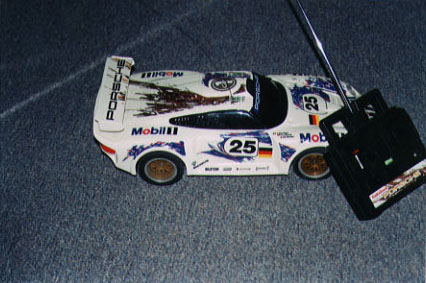
For the final project for EE 476 - Microcontroller Design, we decided to use a radio-controlled car from Radio Shack. We purchased an RC car, removed everything except the body and the motors, and replaced all of the circuitry with our own microcontroller-controlled network. We also built our own controller using just the existing case. For the transmission of control signals, we used a 418 MHz transmitter/receiver pair purchased from Abacom Technologies. We used two microcontrollers in this project, one for the controller, and one for the RC car.
The goal of our final design project was to remove all circuitry from the existing car and controller, replace it with our own microcontrollers, logic, and associated circuitry, and have the car work the same way as when purchased. This goal was to be achieved through a very systematic approach, which we laid out before beginning the project.
To begin with, we set out to have two microcontrollers connected to each other through a null-modem cable using the UART communication protocol. One was to be a transmitter, and the other a receiver. The pushbuttons on one board would light their corresponding LEDs on the other microcontroller board. Once the UART communication was established, we next decided to simply remove the null-modem cable, and in its place, add the transmitter/receiver. Since the Tx/Rx operated in the same way as the UART (each sending an 8-bit data packet), the transition to a wireless communication network was relatively straight-forward. Once wireless communication was established, we proceeded to move our attention to the car.
Before dismantling the car, all voltages, and currents controlling the motors were carefully recorded. Then, all of the existing circuitry was removed, and replaced by our microcontroller, receiver, H-Bridge, and logic controlling circuitry. The car was now controlled by the pushbuttons on the development board, one button for forward, reverse, left and right. The forward/reverse signals operated the rear motors, while the left/right signals operated the front steering motor, which were strictly controlled by the microcontroller's timer.
Once the car was operating correctly via the development board, the next step was to attack the original RC controller. We removed all of the circuitry from it, and kept only the metal contacts on the PC board. The microcontroller and transmitter were then integrated with the controller, replacing the pushbuttons with the new switches on the controller. The original antenna was reattached to our new transmitter, and behold, a working RC car, just like the original, but even faster!
For the program design portion of this project, we wrote two portions of code, one that ran on the controller's microcontroller, and one that ran on the RC car's microcontroller.
The controlling microcontroller's function was to essentially receive commands denoting the direction of the vehicle and output an encoded 8 bit value of these directions. The input signals came from the metal contacts of the switches on the original controller to 4 input port pins ( indicating forward, reverse, left and right) on the microcontroller. The directions are then encoded as 1-byte words which are sent to the transmitter using the UART protocol. The code for the controller can be found in Appendix B - Controller Code.
The function of the car's microcontroller was to provide signals to control the motors. The inputs to this microcontroller came in 1-byte packets from the receiver, each one indicating the state that the car should be set to. As mentioned before, we implemented the UART receiving protocol at this end. The outputs consisted of 4 signals on port pins (Driving Direction, Driving PWM, Steering Direction, Steering PWM). The generation of forward and reverse signal was straightforward. The generation of the left and right signals was quite different. Instead of relying on feedback signals to control the steering (which was what the original Radio Shack car did), we took full advantage of the timer in these microcontrollers (TIMER0). The times taken for the wheels to turn left and right, and then back to center were recorded. Then, when the front wheels are to be turned, the left or right signal is held high for only a short period of time, controlled by the timer. Conversely, when the wheels are to be brought back to center, the timer is used again to make sure the wheels are brought back exactly to the center position. The code for the RC can be found in Appendix A - RC Car Code
This RC car project was a good balance of software and hardware. Once the software aspects of this project were clearly defined, we set out to turn the microcontroller's signals into voltages and currents that the motors could operate on. The main hardware components of the car included multiple batteries, the logic circuitry and the H-Bridges for both driving forward or reverse and steering left or right. The car contained two batteries: one 9.6V battery from the original car was used to power all the motors (the front motor running at 5V due to a voltage regulator), while an ordinary 9V battery was used to power the microcontroller, again through another 5V regulator. Although it may have been possible to power each from one battery, we believed it was best to keep the motors and microcontroller separate.
First, we constructed two identical portions of the logic circuitry seen in Appendix C, one generating forward and reverse signals (and their respective complements), and one generating left and right signals (and their respective complements). The inputs were just the PWM signal and a direction. We used custom IC's for the logic. Now, the signals leaving the this portion of the hardware were either 5V or 0V. These voltage levels were perfect as inputs to the front motor H-Bridge which operated on 5V, but would not be acceptable to run the rear wheels. Therefore we added 4 transistors to boost the voltage from 5V to 9.6V. The H-Bridge part that we sent away for was not acceptable, thus we needed to construct our own H-Bridge to control the motors. Again, the schematic for the H-Bridge can be seen in Appendix C. We originally used Motorola's TIP31 and TIP32 transistors for both the driving and steering motors, but they were not providing enough power for the driving motors, so we upgraded to the TIP102 and TIP107 series, which provided plenty of power, more than the original car! We also needed to integrate the microcontroller onto the car. To achieve this, we used a 4MHz crystal oscillator, and two 22pf capacitors to provide an accurate clock, and a 5V regulator connected to the 9V battery to provide power.
The circuitry for the controller was also completely built by us. The microcontroller for this portion again contained the oscillator and two capacitors, and was powered by a 9V battery (with the associated 5V regulator). The original two plastic levers, one for forward/reverse, and one for left/right, were kept intact. We soldered on 4 wires to the original metal contacts. These 4 wires were then Port B inputs to the microcontroller, with the associated pull-up resistors turned on. We wired the middle metal contact of each lever to ground, so that when the contact connected the middle plate to the port pin, it was pulled low, detected by the microcontroller, and an appropriate signal was sent to the transmitter. In addition, to cut down on power consumption by the microcontroller, and ease of use, we added a mechanical switch to turn the controller on and off.
My partner and I accomplished all of the objectives that we set out to achieve. Our goal was to create a radio controlled car that had the same functionality as the original. One key result of the design is that our car is clearly faster than the original. We could have increased the speed further by adding larger power transistors, except that we were not sure how much current the rear motors could handle. In addition, the steering is quicker also. This again is due to the larger power transistors, and larger voltage. From the original measurements, the steering motor was running on 4V, and we were powering it with 5V. Another key result of our design is that we were able to run our car for longer periods of time than the original car. This is due in part to the fact that we used two batteries. The 9.6V battery pack now only has to provide power to the motors, while the 9V battery we added powers the microcontroller, and direction generating signals. Since our original objective was to get the car running as it was originally, we decided it was necessary that all of the circuitry be transferred from the large, heavy breadboards to smaller PC boards where the components were soldered on. This made for cleaner, more compact, less noisy circuitry, and more importantly allowed the cover to be placed back onto the car! The same was true for the controller. We could have just controlled the car from the microcontroller board, using pushbuttons, but we envisioned a stand-alone controller, namely using the original. Additionally, the switch we added cut down on power consumption. Another great feature about our car is it can be rammed into cement walls from any direction, dropped and flipped without missing a beat. Really, it can, and we've tested it!
This project turned out great, but there are still a few things we would like to add, and one minor thing we would have done differently. The change we would have made was: instead of using timer0 to control the steering, we would have used the feedback signals which came with the steering servo. The reason for this, is as the batteries lose juice, the amount of time required to turn the wheels all the way left or right, or back to center changes. Using the feedback signals would avoid this because the motor would keep turning until the wheels were fully turned or returned, independent of time and voltage.
A few additions we have thought about would be adding some minor bells and whistles like a horn and lights, but a major improvement would be to add analog control to the car. That is to say, the speed would increase as you pushed the lever higher and the wheels would turn farther as you pushed the turn lever farther. This would be difficult with our car because the controller has no support for this. The contacts are all or nothing, so new controlling circuitry would be essential. This would be the only hardware change though, as the RC car could support analog control with only a minor upgrade to the code in the microcontroller, and the use of the 8535 MCU instead of the 4414 MCU.
Click here to download the RC Car Code Version 2.0
Click here to download the Controller code Version 2.0
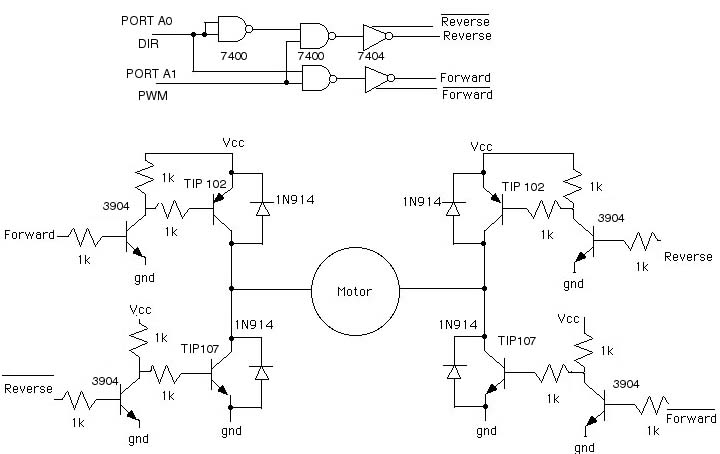
1. Control Logic and H-Bridge Circuitry for Driving Control
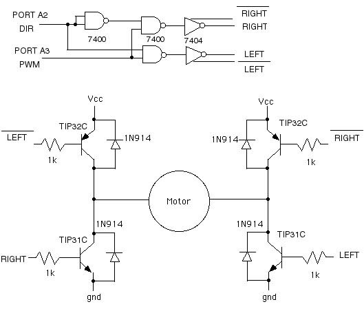
2. Control Logic and H-Bridge Circuitry for Steering control
Appendix D - RC Car Photo Gallery:
1. The Initial Radio Shack Car
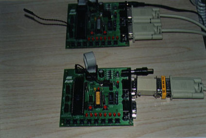
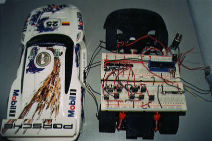
2. The 2 Development Boards used to simulate the Controller and Car
3. The Radio Shack car with the Cover Off
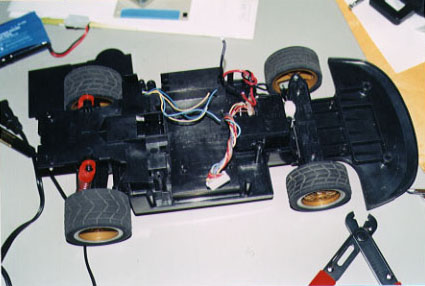
4. Radio Shack circuitry Removed
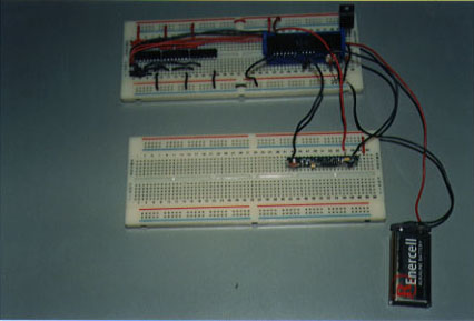
5. The logic circuitry which generates Forward, Forward1,
Reverse, Reverse1 signals with Receiver and standalone MCU
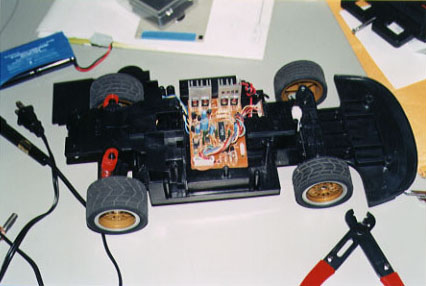
6. The Fully Working Prototype RC Car
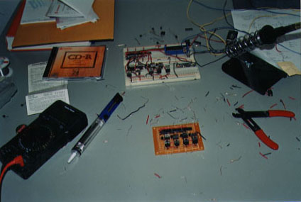
7. The soldered version of the Prototype after 12 hours of soldering
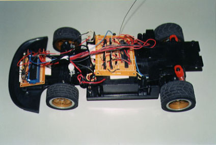
8. The fully working RC Car in it's final stage. Microcontroller and
receiver on the front, and motor controlling circuitry in the middle
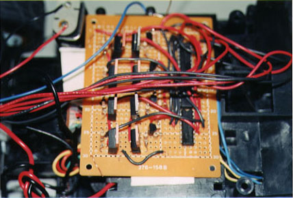
9. Zoom in of the motor controlling circuitry

10. Zoom in of the Microcontroller and Receiver
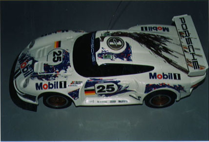
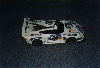
11. Our final RC Car with it's cover on
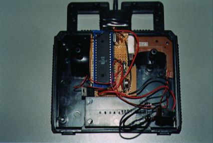
12. Our new and Improved controller circuitry
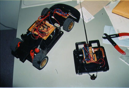
13. Our RC car and controller completed and ready to go
14. Finally, the finished product, vrmm vrmm
Appendix E - Radio Shack Specs: