Félix Rodríguez
Alex Osbun
EE476 Final Project
Automatic Etch-A-Sketch Controller
Introduction
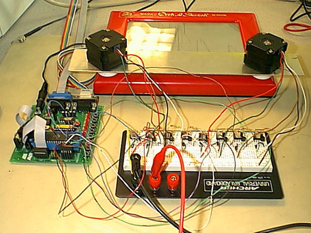
For our final project, we set out to write a Controller for the classic toy, the Etch-A-Sketch. What this basically means, is that we use an Atmel micro controller to control two stepper motors connected to the knobs of the Etch-A-Sketch. Thus, an order by the chip to the motors would cause different angled lines to show up in the Etch-A-Sketch making it possible to draw complete pictures automatically.
Since we did not want to force the chip to contain just one picture, it would have to connect to a computer using the UART, and download pictures from there. Thus we will write a small drawing program in Windows that lets a user draw its schematic, and send it directly at the serial port.
The reason we chose to do this project was twofold. First, we thought it would be very interesting to actually see an Etch-A-Sketch move by itself. Secondly, we thought that the amount and diversity of the work would be ideal. First we would need to write two large programs, one in Atmel Assembly, and we’d have to build a circuit. Also we were curious on how Stepper Motors worked. Finally, since our budget was limited, it was ideal because the only two items that we needed to buy was a power supply and the Etch-A-Sketch toy.
High Level Design
Our setup has four main sections: the Computer, the Micro controller, the stepper control, and the Etch-A-Sketch, in serial order. All four sections are relatively decoupled from each other, with the exception of a small communication script in between each section. This design is based on the standard computer network design where there are seven layers separate from each other, and it has a number of advantages. First, the decoupling enabled us to work efficiently in parallel, taking separate tasks until the final testing day when we join all the pieces. Thus, Felix would take over the first two sections, the Computer, and the Micro controller program, while Alex would take the last two. Second, it has good modularity, in that we could easily switch any one of the four sections with something else that has the same communication interface, and the remaining items would not have to be changed at all.
The first step is the computer program. This would be a standard windows program written in C++. It is basically a line drawing program, with added Serial Port functionality so that it can send the points to the Micro controller when it is requested. It works by letting the user draw a series of connected lines. The program would then format the lines so that they fit in a byte (125 values, positive and negative with the extra 6 items reserved for handshaking, etc).
Then, whenever requested this collection of bytes (for the points, with x and y values alternating), are sent directly to the chip after a simple handshaking procedure. A class description of this program is attached in the appendix, and a more thorough description is also attached in the Program Design section of this document.
The second step is the Atmel Micro controller and its program. This program basically has three functions, each called by one of the three buttons on its board. The first, is a simple testing procedure that loads some specified values in memory. This can be used not only for our internal testing, but also for easy diagnostic of the system in case something breaks (similar to the auto tests in printers). The second button is more interesting, it also loads the specified values in memory, but it loads them from the UART input. Thus, it contains a compatible handshake with the computer, and then it reads values from the UART one by one until it finds the end code, or it runs out of memory.
The third button takes care of sending the necessary voltages to the next step. It loads the values from memory one by one. Then it alternates between x and y values and does the following: For x values, it converts them so that they are always positive, makes a note on its sign, sets the delay factor for y, and the counter for x. For the y values, it does the same conversion, but it only sets the delay factor for x, and no count value. The reason for this inverted formula is this:
  CountX        DelayY
 --------  =  ----------
  CountY        DelayX

because CountX * DelayX = DelayY * CountY
Thus we set count x, and the two delays, and the y count automatically sets to the correct value if the timers have the correct delay. The only limitation of this system is that I cannot deal with values of 0. My solution was simple – convert all zeros to ones. I can’t have a straight horizontal or vertical line, but the distortion is not very significant anyway.
Program/Hardware Design
For a better understanding of the windows program, please refer to the attached class description, and the supplied code. The general structure of the windows program is the standard Single Document/View Architecture engineered by Microsoft. This setup was preferable because it conveniently splits up different parts of the program logically. Also, Microsoft has a number of tools that support this Architecture, which simplified development.
The way it works is that the main function, called CEtchASketchApp, builds a window and creates three separate objects that control this window. Thus, when a message is sent, it goes to all three classes until it finds the one that controls that specific message.
The first object is the CetchASketchView object. It is in charge of handling all the drawing and input functions. Both of these connect to the Cpoints structure in the CetchASketchDoc (described below). The drawing basically goes through all the points in order and traces a line through them. Input basically adds to the point list. It also, however, makes sure that the points it adds are not bigger than 128 in length because that would crash the Micro Controller. Thus whenever it spots a longer distance, it splits the line into two. There is also a limit to the number of points, which is directly related to the number of points that the Atmel memory can hold.
The second object is the CetchASketchDoc. This is basically a controller for the Cpoints object. It includes file saving and loading by populating this object. It also includes a number of visual features such as warning boxes when saving, its own type of file (.eas) for easy lookup, and a feature to restart the Document completely, by clicking on new on the menu. The Cpoints object is basically an array of the Windows standard Cpoint object. It contains a number of functions for adding and viewing the points that simplify its access, along with a lookup of the maximum value in case we overextend by mistake.
The final object in the Architecture is CmainWnd. This object controls the general button management and any other item not used by the other two objects. It controls a couple of tweaks such as the About Box, which shows author comments, and the status box in the bottom. It also controls the Program Atmel button in the menu.
This menu button when called, first initializes the CserialPort object, which will be described soon. Then it takes care of handshaking – a simple Send FF, and receives the same. Once it gets past that, it then streams a string of all the points for the Atmel Controller to catch.
The Atmel Controller code as explained above, can basically be divided int three separate button sections, the initialize, the UART, and the two timers. The Initialization is fairly straightforward. It’s a linear code that basically starts up the UART and the Timer, initializes all the values, writes “Etch-A-Sketch” on the screen and goes on. The UART control is also fairly straightforward. It is basically the same circuit that was used in Lab 4. The three buttons are implemented pretty much in the same way that was described in the previous section, so I will not repeat the same here.
The two timers work generally the same way. One controls the the bottom four bits and the other upper four bits of the output pins. Thus we use the bottom four bits for the horizontal movement, and the upper four for the vertical movement. The timer values described in the previous section are used to set the interrupt delay of the timer. Thus, the interrupts alternate at differing speeds, and keep the TimCount calue as memory for how much they actually have drawn up to now.
This system means that the steppers do not actually move at the same time, but they alternate in very small steps. Thus we get a slightly jaggy picture, much like the aliasing done when drawing a diagonal line in a computer screen. The output is also sent to two ports at the same time. This was done for debugging purposes as one port can be connected to the leds and we can find what exactly is going on visually.
In order to drive the knobs on the etch-a-sketch we use a couple of stepper motors. These motors use a 12 volt supply. The manner in which our stepper motors works is rather straight forward. Each motor has 5 different color coded lines used to power and control the motor. The black line is used to supply the 12 volts to the motor. The rest of the four lines are used to control one of the four coils in the motor. For example, if "coil 1" is magnetized, then a permanent magnet aligns itself to the charged color. This action thus rotates the shaft of the motor. In order to magnetize a coil, the corresponding wire has to be connected to ground. This causes voltage to flow through the coil, thus magnetizing it. Considering that the motor had plenty of torque to move the knobs on the etch-a-sketch, we decided to power one coil at a time, as opposed to two coils, which produces more torque, but takes up more power. In order to make the motor shaft rotate clockwise, four coils were energized in succession. The order was first the red wire, then the green, brown, and white. This sequence is repeated as much as desired. In general, in order to make a line (on the etch-a-sketch) which is about half an inch long required the sequence to be repeated about 18 to 20 times. In order to make the knobs go counter clockwise the sequence is reversed (white, brown, green, then red wires sent to ground).
Well, this process seems simple enough, but we had to figure out a way to switch the current from the different coils in a quick manner, with the use of the five volts given to use by the PortA pins. In order to do this, we decided to use transistors, which would be turned on (saturated) and off by the micro controller. We ended up using a couple of transistors for each wire that was would allow current to flow through the various coils. Our initial design used Tip31C power transistors. These are npn transistors which are rather "heavy duty". One of our big problems was the inability to supply enough current to the transistor base in order to switch in one. So we eventually used 3904 transistors to help out.The 3904 amplified the current so that we had enough current to turn the larger power transistor on. We also connected 1K resistors to the base of the 3904s. This assembly is used eight times, one for each coil. The schematic for the picture is shown in figure 1.
Figure 1. This circuit is the switching circuit we used.
When 5 volts is supplied to the base of the 3904 transistor, the switch is turned "on". But it is also interesting to note that in order to have the motors give use the desired response, the high voltage given to each of these circuits had to be very short, or else the shaft of the motor would begin to vibrate, rather than turn hard and stay when having a coil connected to ground. This is probably due to the fact that the power transistor are not completely saturated. What is happening is that it is flickering on and off, thus causing the shaft to vibrate.
We also had to solve a problem of actually mounting the motors to the knobs of the etch-a-sketch. One of the initial concerns was that enough torque may not be provided by the motors. If this was the case, then we would have had to come up with some sort of gear assembly. But we decided to go with a straight coupling with the use of the white knobs which came with the etch-a-sketch. And fortunately we ended up having enough torque in order to give us what we needed. We also had to create some sort of mount for the motors. This ended up being a simple bar of metal with holes drilled in it. The mount and the coupling were creating with the help of Nathan Jauvtis, a Cornell mechanical engineering student. In the end, everything fitted just about perfectly for us.
Results of the Design
Unfortunately, we were not able to meet our main objective, which was to create a project in which we can draw something in Windows and replicate it on a etch-a-sketch with the use of the micro controller and a couple of stepper motors. But we were able to make the stepper motors actually draw on the etch-a-sketch, which ended up being very satisfying. The mount and coupling for the motors worked very well. Also, we were probably somewhat fortunate that the motors had enough torque to be able to turn the etch-a-sketch knobs. In order to make the knobs "lose", and making the probability of the straight coupling work we also had to "break in" the toy. In other words, just play with it a lot.
What we would do different next time
We spent a long time trying to get the serial connection to work in a clean fashion, and in the end I don’t believe it paid off. The plan was to create a completely separate class that could be reused for any Serial Interface I might want to create. This implied having two child threads controlling the input/output along with a myriad of generic options. If we had done this again, this functionality would not be here. We ran into some evil threading synchronization problem that took way too much time to fix.
Another item we would have done differently is gotten a better power supply. The one we had, used very little amperage and we had a hard time keeping it powered. Something better would have definitely made our life easier.Unfortunately a power supply with a larger current was several times more expensive.
We tried to do most of the project in parallel, which made things efficient. But at the same time we found it difficult to test how the various parts worked together since during the last two weeks our schedules were not compatible at all. It would have helped us greatly in completing our project completely if we had more time to test the various components together.
Program Listing
Windows Source(ZIP)
Windows Program(executable)
Diagrams of Code