Introduction:
One of the newest and fastest growing additions to the digital age in the 1990s has
been the handheld personal computer. Given a little flash memory and a good LCD, anything
is possible and commercial products like the 3Com PalmPilotâ
and IBM Workpadâ are flourishing. But as these products expand
their functionality so does their price. Last year, a more downscaled device Frankin Rexâ card sold very well because it offered a small portable data unit
at a minimal cost. In fact, it only served as a data display device for the data that was
transferred from the PC, and it functions using just a few buttons rather than using a
more expensive LCD that can accept input using a pen-like device which is detected when
pushed on the screen. This year they have improved the card in the Rex Proâ version to take input using additional buttons to scroll through
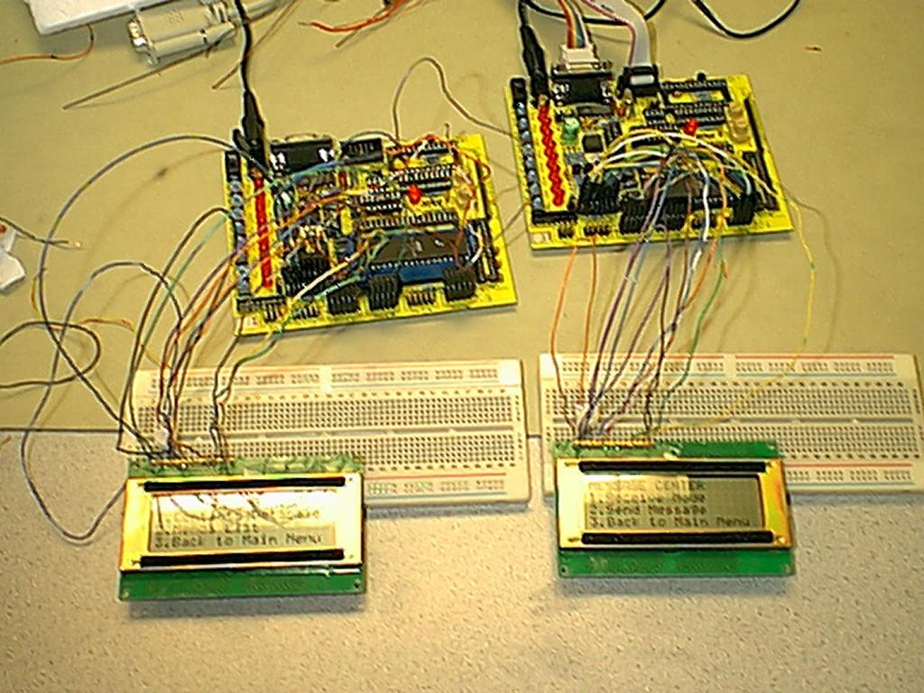
alphanumeric characters. In this project we attempted to produce a similarly functioning
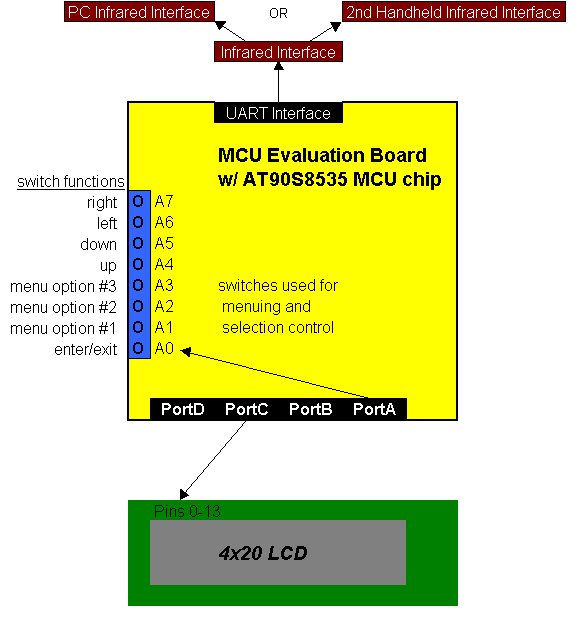
device using an Atmel AT90S8535 microcontroller, its Atmel evaluation board, and an Optrex
4x20 LCD. In addition, we also attempted to include an infrared communication interface on
the prototypes which is used for downloading/uploading data to the PC, as well as for
messaging between two devices, which is only a recent addition to the high-end handhelds
like the 3Com Palm IIIâ. This IR message transfer ability has
been especially appreciated by users who enjoy not having to physically connect the
devices to their PC hardware (in a PCMCIA slot for example), and corporate users have
found it useful as a way to silently communicate across a room or even just across the
table at a boring meeting.
Given this hardware, we had to decide how to create a useful interface for the user on both the PC and handheld ends. For the PC, we created a Java interface that can browse and edit the data, which is stored logically in a contacts database and a memo database and physically in a file which can be loaded using the standard Windows file selection interface. The interface provides for browsing both databases one entry at a time, saving the data to the file, and sending or receiving to synchronize data with a handheld device. Each contact entry provides space for a first name, last name, address, and phone number, while memo entries allow space for a date to accompany each memo. The handheld interface relies on the buttons provided on the evaluation board to browse through the menu options to view/edit the data, synchronize data with the PC, and send messages to another device. Data or message entry and editing is performed by using the buttons to scroll through the characters and moving to the next character space using left/right buttons.
High Level Design:
The most significant portion of the project design was in the development of the user interface in Java for the PC and in assembly code for the handheld prototype. The challenge was to create a useful interface while maintaining a relatively easy data-handling scheme that could easily be ported between the two. The reasoning behind the use of a Java application on the PC as a way to perform data entry was twofold. First, it offers the user the standard Windows PC data entry interface that they are accustomed to using, which is much quicker and easier to use since it has a full keyboard for input. Secondly, it provides a large data storage capability for data entry that is not always necessary for downloading to the handheld which is a more permanent storage space for the data to be backlogged on if required. The handheld on the other hand, is designed largely just for viewing the data. The data entry done by scrolling through the different available characters is more time-consuming than when done on a full keyboard, which is obviously an impractical addition to the pocket-sized device. Even adding a small keypad would not help to the degree necessary to justify its inclusion. A 16-key input would only about double the amount of available key inputs and even these are nothing comparable to a keyboard that users are often either formally or through time and experience trained to use rapidly.

When synchronizing the data between devices, it needed to be organized in a fashion that would allow for finite storage in SRAM on the handheld's mcu and provide terminating characters on the handheld for ease of handling when displaying them on the LCD.
On the PC side, this led to the Java interface allowing a finite number of characters in each database entry field, which then allows the mcu to be able to count on only having to store characters counts corresponding to the field in the entry. These limits were as follows:
Therefore when the handheld is receiving data from the PC, it can trust it to send only as
much data as it is able to store per contact. The PC is allowed to send more data than the
handheld has SRAM storage available to hold, but this case is handled by limiting the
number of each databases' entries that are accepted by the handheld during a receive
operation. All extra entries are just disregarded by the handheld. This was very necessary
with our device prototype because the 8535 mcu limited the storage in SRAM to 512B.
Another portion of the data communication protocol design between PC and handheld is that
when one is that the receiver dumps its past data and only stores the new data from the
sender. This requirement simplified the data exchange because doing it otherwise would
have necessitated a data comparison with something along the lines of numeric contact and
memo id specifiers. This also allows the user to accumulate data on the PC end in its
plentiful storage while only storing the necessary information in the handheld's limited
storage.
The last portion of the interface design was in the message exchange between handheld devices. The devices were designed to simply take the message entered and send it to the receiving device. The receiver meanwhile is set to wait for all of the data to be received then displays the message in its entirety. The messages are not stored, however because we consider them to be temporary entries which are not worth storing in SRAM because of the space that would be taken away from the main data in the contacts and memos databases. Also worth noting here is that the message send and receive is driven by the user, as is the synchronization. The handheld and Java operating programs are designed not to accept or send data transmissions unless it they instructed by the user to do so. This means that in order to synchronize data with the PC, the user must set one to receive then direct the other send the data. To send messages, the other handheld must be instructed by the other user to receive an incoming message.
Program/Hardware Design:
The handheld program is centered around its menu driven interface. The options available on the handheld were too numerous to all be available immediately on start-up so they are accessed through successive drill-down selections. Therefore the current menu state determines the functionality of the buttons and the device. On reset, the program naturally begins at the main menu where the user can select the contacts and memos databases' menu, the message center for handheld-to-handheld communication, or the synchronization mode for PC-to-handheld communication. Every menu is headed on line one with its respective title and the remaining three lines are used for the three options. Each of these subsequent menus then provides two options with the third being a return to the main menu. All of the menu titles and options are stored in and displayed from the 8535 mcu's flash memory as shown below:
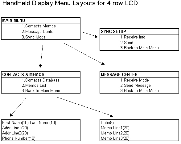
The initial menu/main menu allows selection between contacts and memos database browsing/editing, entering message center menu, or entering the synchronization menu. From the contacts and memos menu, you can select to load up and browse either the contacts database or the memos database. Once within the contacts database browse mode, you have these options:
Note that the exact same button functionality exists in the Memos database browse mode. The Add and Delete functions complement each other in that they only allow the number of contacts to stay at or below the initial programmed value according to the device's SRAM constraints (in this case it was 2 contacts and 3 memos). The Delete function will allow all entries to be deleted and once that happens, the user is returned to the Contacts and Memos menu. The Add function detects an attempt to add an entry when the database is full and simply ignores the request. When there are initially no entries in the database, then selecting either contacts or memos browsing creates one new blank entry that is displayed for the user.
A secondary mode to browsing is editing which is accessed by button 3, and it switches the button functionality as follows:
Here the character selection proceeds as follows: a-z, A-Z, 0-9, _(space), punctuation, and then parentheses/brackets. There is a line character count which limits the space available per line depending on the data input for the line (i.e. 8 characters for the date, 10 for the phone number, etc.).
The second option from the Main Menu is the Message Center, which allows messages to be sent and received from another handheld device. The first option is to place the device in Receive Mode where it waits for another device to send it a message while displaying a waiting message "Receive Ready" and then it displays the incoming message once the receive is complete. Pin0 allows you to exit the mode after reading the message. The second option is to send a message. In this case the display is blank and you edit the message before hitting Pin1 to send it with Pin0 exiting. The editing is done through the same Pin configuration as in contacts and memos editing functionality.
The third option from the Main Menu is the Synchronization Mode, which allows the contacts and memos databases to be loaded from the PC or uploaded to the PC. Option 1 is to receive the data. The device program waits for the PC to send the data headed by 0x01 then 0x04 then 0x05 followed by all of the data for both the contacts and memos with each terminated by a 0x01. Once the receive is finished, "Receive Done" is displayed for a few seconds then the Sync Menu reappears. The second option of Send Info, sends the data out to the PC with the same data header and terminators as it is received from the PC, which is done in both cases to achieve a much greater probability of accurate data being received.
The hardware used for the sending and receiving was the RS232 interface on the Atmel evaluation board and the COM2 serial port on the PC. The interface was intended to be done through the infrared transmitter and receiver pairs that we attempted to use, but the transmission media ended up having to be the serial cable between the handheld and PC and a null modem cable between devices (for connecting female to female adapters). We were also attempting to use the AT90S4414 mcu initially, but we ran out of flash memory to program with because it only provides 4K of flash. The AT90S8535 also provides twice as much SRAM at 512B than the 4414, which became very useful once we determined that we needed at least 2 contacts and 2 memos to demonstrate the full functionality of the handheld device. Once switching to the 8535, we encountered a switch connection problem where a button push was not able to be detected on PortB so we switched the connections to PortA, which left the LCD power (PortB0) and ground being taken from PortB. Note that rather than change all of our code to reflect this, we switched the declarations of the two ports as shown in our 8535def.inc file (listed with all files at the end of this document). The connections not listed on the schematic below are as follows (also note that PortD0 and PortD1 are taken as RS232 data pins):
The JAVA program provides a user-friendly interface where data can be entered and manipulated in a plethora of ways. Some of the functions of the GUI interface are:
The following is a screen shot of the program after loading a file:
The JAVA communication interface is a little awkward, so particular setup steps must be taken in order for it to function correctly. The program also requires that the JAVA API package that allows serial communication be installed. Before the program can be run the following commands must be entered:
path = %path%;c:\jdk1.2\bin (assuming that the JAVA directory is c:\jdk1.2)
cd to path were files are located
javac -classpath c:\jdk1.2\lib\comm.jar;. *.java
java Frametest
For serial communication on a port other than COM 2, the Java code needs to be manually edited. Just search for COM2 and change it to the appropriate COM port. The JAVA code for serial communication was adapted from the JAVA communication API package, the data input Java file Reader409 was borrowed from a CS409 project, and all interface and data manipulation code was designed for use in this project.
The main class in Frametest.java is implemented as a runnable thread, so that receives can be "interrupt driven." Basically an event listener monitors serial events on the COM port and performs a defined action depending on the type of event. The one used in this program is the DATA_AVAILABLE event, which is triggered when information is received. Once this event is received, the data is stored and the monitoring of the port continues. There is a status Boolean that only allows characters to be received when it is set to true. It is set when the receive button is pressed in the GUI interface. The send routine is not like that used in hardware, because while all the characters are being sent, the program can do nothing else but that task.
The data structures used in this program to store the data are all of type String. The two objects that were designed are contacts and memos. Both consist of several pieces of information and both have special methods to return the data in the appropriate form and of the appropriate length.
The data stored in contacts is:
The data stored in the memos is:
The information stored from and retrieved by the program is stored in a flat format. All
information is visible and for the most part decipherable when loaded into a text editor.
There are two special characters used in the storage of information and they are ô (alt
-1,4,7) and § (alt - 7,8,9). These characters are used to separate different data fields
and to identify section headers. The format used to store data on the PC is similar, but
not the same as that used to store data on the unit. Due to storage constraints it had to
be slightly modified. The manipulated version used on the unit also simplified some
operations.
Loading files is very simple. Once the user has entered a file name in the Dialog Box, then the program systematically steps through the file line by line deciphering the data and storing it in the correct location in memory either as a contact or a memo. During the loading of the file, the state Boolean can be in one of two states; memo or contact. If it is in contact mode, then it means that is has read the line in the storage file that delineates that contact information follows. The same holds for memos. Once in a mode, the program will continue through the fields that it is expecting. These fields are outlined above.
The current program has a limit of 20 memos and 20 contacts, because we thought that that was the amount that we were going to store on the unit, but we were unable to get the memory needed integrated into the design. The handheld unit knows how many of each it can handle and will discard any information transferred after that limit has been reached.
A sample PC file may look like this:
§Contact§MorganôBrianô105 College Ave Apt #1ôIthaca, NY 14850ô607ô275ô3469ô
DillinghamôRhettô1600 Pennsylvania AveôCentreville,VA 12356ô607ô256ô0495ô
§Memo§
03ô15ô1999ôThis is a reminder to do EE 476ô projectôô
3ô16ô1999ôMessage #1ôôô
03ô18ô1999ôMessage #3ôôô
03ô9ô1999ôMessage #4ôôô
03ô17ô1999ôMessage #2ôThis is a test of orderôô
Since the code for the PC was written prior to that of the handheld unit, there are different transfer and retrieval formats than those used in the PC files. Instead of the characters mentioned above, the numbers 1,2, and 3 were used to delineate fields. These numbers are not ASCII characters, but bytes. Since they are not included in the character set that we allow on the handheld unit, we do not need to worry about getting faulty delineators. The 1 is used to delineate the separation between the end of contacts and the beginning on memos. A 1 also appears at the end of memos to signify the end of all the data. The 2 serves the purpose of separating fields. For example the phone number 6072560495 is stored at 607 (byte 2) 256 (byte 2) 0495 (byte 2). This provides us a rigid format, which can be used to locate information with respect to other information. For example, it can be used to find the last name of the Contact when located at the beginning of the contact. Using the field delineators, we know that the last name begins after the first (byte 2) that we come across. As for the 3, it is used to separate contacts from other contacts and memos from other memos.
A sample handheld unit memory space may look like this for the PC file above:
__Rhett Dillingham1600 Pennsylvania AvCentreville,VA 123566072560495_Brian Morgan 105 College Ave Apt Ithaca, NY 14850 6072753469__03091999Message #4 _03151999This is a reminder to do EE 476 project _03161999Message #1 __
Equivalent meaning with byte value in {}
{1}{4}{5}Rhett {2}Dillingham{2}1600 Pennsylvania Av{2}Centreville,VA 12356{2}6072560495{2}{3}Brian {2}Morgan {2}105 College Ave Apt {2}Ithaca, NY 14850 {2}6072753469{2}{3}{1}03091999Message #4 {2} {2} {2}{3}03151999{2}This is a reminder t{2}o do EE 476 project{2} {2}{3}03161999{2}Message #1 {2} {2} {2}{3}{1}
Since the information comes in so quickly from the handheld unit, the information is temporarily written to the Download file. Once all the information has been received, the file is parsed and the old data in the program is replaced by the data downloaded from the handheld unit.
One thing to note is that during downloads and uploads; the data is not merged, but completely overwritten. Due to the lack of some type of time stamping device, there is no real way to determine what information is newer.
Results of the Design
The final product that we ended up with was for the most part exactly according to the specifications that we came up with. In terms of accuracy all we needed to deal with was data consistency during serial communication. During some preliminary tests that we did with the JAVA serial communication utilities we found that it sometimes was unreliable. After further examining of what happen when the data was sent correctly and when it wasn't, we noticed that if the first character was received correctly then the rest was received correctly. In order to use this fact to our advantage, we used an initialization string that consisted of three byte values (1,4,5). If we did not receive these 3 bytes in this order, we aborted the receive, because the following data was most likely bad. As a result of this initialization string we had no further problems with bad data.
The one major inconvenience of or project is the data input on the handheld unit. The archaic fashion with which we allow data to be inputted was chosen over keypads, because our goal was to make a small device that was easy to carry with you. A keypad would have added to much area. Also, the main reason for the option to input data was not to input complete information, but to update what was already there. The JAVA program provides a much easier and user-friendly way to input and manipulate data. So, a way to think of our product is more like a REX card with the added feature of edited, compared to seeing it as a slimmed down version of a palm pilot with a harder to use interface.
Differences the Next Time Around
The final product is in actuality not all that practical because of memory constraints. If
we were able to effectively add external SRAM, then the number of contacts and memos
stored on the handheld unit would grow significantly. Also, we ran into some trouble with
the RS-232 and the Infrared interface between the handheld units and the PC. For some
reason the voltages coming out of the receive (RXD) pin was stable at ~ -11V when not
sending and fluctuated in the negative region when sending. We were able to successfully
get the IR circuit to send at close distances, but we were unable to get the expected
values, because the input receive port would pull the voltage at that pin to zero at all
times. Thus, we really would have been better off if we spent quite a bit more money
(~$40-$80 as opposed to $4) and bought commercially tested parts that had better red
filtering and better range. With these two changes and a nice package with power saving
features, this would be an inexpensive product that would be really useful in day to day
life.
On more of a software/functionality side, the programs could be revised as follows:
Appendix A:
Appendix B:
See the schematic with listed connections in Program/Hardware Design section.