EE 476 Final Project
Jonathan Roffman & Theresa Thomas
Cornell University
May 3, 1999
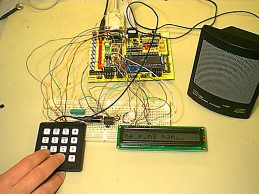
For our final project, we used an Atmel AT90S8535 microprocessor to create a hangman game. The letters are displayed on a 16-character LCD, and are input ("guessed") using a 16-button keypad. The 8 LED's on the Atmel development board are used as our "hanging man" - one lights up for each wrong guess. We also attached a speaker to our game which adds sounds to our game.
We programmed our game to randomly select from among nearly 150 different puzzles, although there is enough room in Program Memory to hold thousands of puzzles. A puzzle can consist of any combination of 1-15 characters including spaces.
Design
Our design incorporated many different parts of previous labs as well as original code. The following state descriptions outline the functions of our game.
Reset:
At reset, we initialize the three counters and the LCD. The LCD initialization and control code is the same as that used in previous labs.
State 0: Wait for "New Game"
Our code then goes into a keyboard polling loop that waits for a button press from the keypad. The keypad decoding is handled by the same code used in previous labs to decode button presses. The only valid button press at this time is a '1' which is the signal to start a new game. All other key presses leave the game in state 0.
State 1: Read in a Random Puzzle from Program Memory
Due to the vast amount of storage available in Program Memory (8 kilobytes) and the compact size of our code(~1 kilobyte), we chose to store our puzzles in Program Memory. They begin with the label "message:" and consist of a series of ASCII characters (1 byte per character). Puzzles are seperated by a terminating zero (0).
To randomly select a puzzle, we read the value of TIMER1 at the moment the user presses "New Game." We manipulate that value with a series of shifts and logical functions until it is a sufficiently random number that is no larger than the number of bytes we use to store puzzles. We then add that random number to the location in memory of the label "message:" and access that memory location.
State 2: Find the start of a puzzle
Since the random number added onto the location of "message:" may point to any letter in any puzzle, we need to find a terminating zero (0) to know that we have found the beggining of a new puzzle. Therefore, our code goes through a loop where it loads a byte from program memory and compares it to zero. Once it finds a zero, the next letter will be the start of a new puzzle.
State 3: Load the puzzle from memory into registers
We now store the contents of the puzzle in registers so that they can be easily and quickly accessed and manipulated. For this task, we use the Y-pointer to point to registers r1 through r15. We increment this pointer as we read each new letter in and loop until we find a terminating zero. At the same time, we increment a counter to hold the length of the puzzle.
State 4: Print dashes on LCD in place of letters
Next, we print dashes (actually underscores) on the LCD. We print the same number of dashes as we counted in State 3. At this point, we added an immediate guess of the "space" character to our code. This causes the LCD to print all the spaces in the puzzle and output a tone to signal to the user that a new game has begun.
State 5: Guessing letters
The game has now begun. Our code returns to the keyboard polling loop where it waits for button presses. In order to have the capability of 26 possible guesses (one for each letter in the alphabet) on a 16-button keypad, we use the A,B, and C keys on the keypad as function keys, selecting the 1st, 2nd, and 3rd letters assigned to each number respectively. The number represent letters the same way a telephone keypad has letter-number associations. For example, pressing "B" and then "3" would result in a guess of the letter E since 3 corresponds to the letters DEF on a telephone keypad. There were two exceptions - Q and Z - which do not appear on the numbers 2 through 9, so we use the 0 button to implement those.
This state therefore contains 2 polling loops. One to wait for the function key (A,B, or C) and another to wait for the number key (2-9 and 0). In the first loop, we store the value 0 for A, 1 for B, or 2 for C into a register called "abc". Once the number is pressed, we store the ASCII value of the first letter that is associated with that number into a register, and add to it the value of "abc". This gives the proper ASCII value for each letter.
State 6: Check if the letter guessed is in the puzzle
This state consists of comparing the "guessed" letter one by one to every letter in the puzzle. After each compare we check to see if we have reached the end of the puzzle yet, and increment the location of the cursor on the LCD. If the "guessed" letter matches at least one of the letters in the puzzle, we output that letter to the LCD, and set a flag. Once the end of the puzzle is reached, we test that flag to determine if the guess was right or wrong. Our code now branches off into two possible scenarios.
State 7a: The letter was in the puzzle - A correct guess!
If the letter appeared in the puzzle at least once, then it has already been written to the LCD in place of the dash that once was in its place. We now play a "correct" tone to signal that it was indeed a correct guess. We use TIMER2 preloaded with a certain value to play the tone. This value corresponds to twice the frequency of the tone we wish to play. This code is similar to that from lab 3. We preload the value for a high tone and use the TIMER2 overflow interrupt to toggle the speaker output at that frequncy. The preload value is also stored in Program Memory under the label "right:".
With each correct guess, it is necessary to check if the game has been won by the player. So we perform a compare between the number of letters remaining unseen and zero. If they are equal, the game has been won and we proceed to state 8a. If not, we return to state 5 and wait for the next guess.
State 8a: The last letter has been guessed correctly- A win!
If there are no more letters left to be guessed, the game is over. To reward the winner, we play a winning song. The musical notes in the song can be seen in figure 2. The preload values for TIMER2 that correspond to the notes in this song are stored in Program Memory under the label "winsong:". They are read from memory one at a time, and played the same as the the "correct" tone described above.
Once the song has completed playing, the game returns to state 0 where it waits for a "new game" button press.
State 7b: The letter was not in the puzzle - A wrong guess!
If the letter did not appear in the puzzle at all, there is no change to the LCD. Instead, we light up one of the LED's on the development board. Then we play a "wrong" tone to signal that it was a wrong guess. Again, we use TIMER2, but this time, preload it with a low tone that is stored in program memory under the label "wrong:".
With each incorrect guess, it is necessary to check if the game has been lost by the player. So we compare the number of LED's unlit to zero. If all the LED's are lit, the game has been lost and we proceed to state 8b. If not, we return to state 5 and wait for the next guess.
State 8b: Eight wrong guesses have occured - The player loses the game!
If there are no more LED's left to be lit, the game is over. To show that the player has lost, we play a losing song. The musical notes for this cong can also be seen in figure 2. The preload values for TIMER2 that correspond to the notes in this song are stored in Program Memory under the label "losesong:". They are read from memory one at a time, and played the same as the the "correct" tone described above.
Once the song has completed playing, the game returns to state 0 where it waits for a "new game" button press.
Results
Here is a list of our design goals and how we met them:
What We Would Do Differently Next Time...
Attachments: Assembly code