Standalone Arbitrary Waveform Generator
Final Project Design for EE476 Spring 2000
Introduction
This project extends the sine wave generator developed in a previous lab so that it could source any arbitrary periodic waveform. A menu system displayed on a 4-line LCD allows the user to specify the length of the waveform, the frequency to output the wave at, and the values (from 0-255) for each sample. Four waves of up to 64 samples each can be specified by the user and sourced at a frequency of from 50 Hz to 9999 Hz. Of course the maximum frequency of the waveform is dependent on the length of the waveform. Waveforms which exceed 80 kHz per sample may not be able to be sourced at the requested frequency.
User Interface Design
The arbitrary waveform generator (AWG) had two modes of operation: command mode and source mode. In source mode the AWG sources the selected waveform at the specified frequency after the user starts the waveform from the command mode. While in the command mode (which the AWG starts in at reset) the user navigates through a series of menus in order to setup the desired waveforms for sourcing. From the main menu the user enter data for a waveform, set the frequency at which the AWG will source a waveform, or can select to start a waveform.
When the user selects to enter data another menu pops up which prompts the user to select which waveform (1-4) to edit. The the user is prompted for the length of the waveform. If the user hits enter ('D') then the previous length is retained otherwise it is changed. No error checking is performed on the length specified so that the user could specify a size larger than 64 samples. However, the waveforms are stored sequentially in memory, so specifying 256 samples for waveform 1 would place the data in waveform 2-4 data memory which could cause a problem if care is not taken. Specifying sizes which would exceed the boundaries of the waveform memory is not advisable. After the length is specified the AWG will sequentially display the current value of each sample and prompt the user for a new value. If enter ('D') is hit the old value will be retained. Otherwise the newly entered value will be saved. The values are entered as decimal values from 0 to 255 and correspond to voltages from 0 to 5 Volts. After all the samples have been displayed/modified the AWG returns to the main menu.
When the user selects to change the frequency a prompt is shown at which the user enters the frequency in decimal from 0 to 9999 Hz. Entering more than four digits will result in an incorrect frequency. This entered value is used to source all of the waveforms. The frequency is not associated with any specific waveform. After the frequency is entered the AWG returns to the main menu.
When the user selects to start the waveform she will be prompted for which waveform to start and then that waveform will be initialized and source mode will be entered. The waveform may be stopped by pushing enter ('D') on the keypad returning the AWG to the main menu and the command mode.
AWG Hardware/Software Design
The AWG consists of an Atmel AT90S8535 microcontroller, an 8 bit DAC, a keypad, and a 16 character by 4 line LCD. An STK200 development board was used to easily interface the microcontroller to the rest of the hardware and to allow for programming of the 8535.
The 16x4 LCD interfaces to the microcontroller through PORTD using the HD44780 protocol in 4-bit mode. Simple functions were written to easily print characters to the LCD (putc/printString), move to a new line (newline), and clear the LCD (lcdclr). These functions were then used to implement the user interface. The menu system for the interface is not very scalable and depends upon specific code which handles each individual menu rather than making a generic method for creating and displaying a menu.
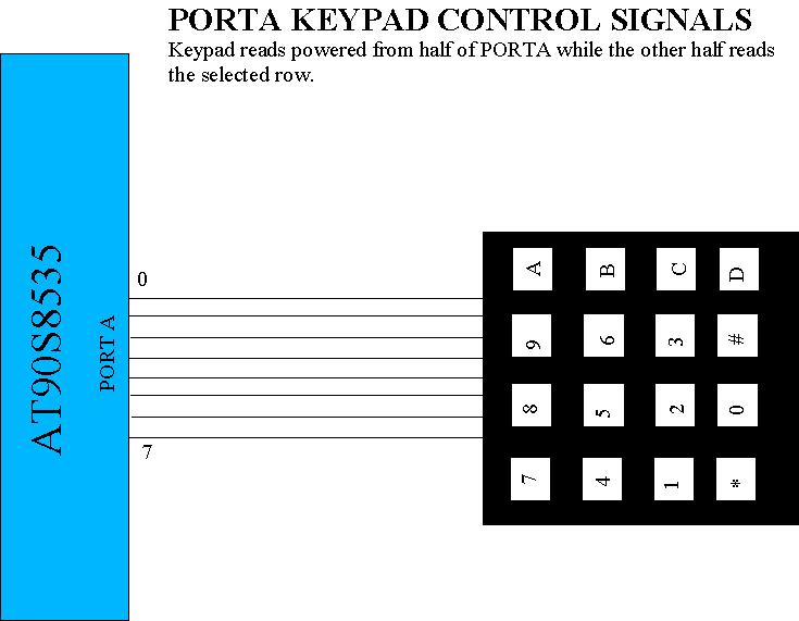
The keypad connected to PORTA has 16 keys which include the numbers 0-9, letters A-D, '#', and '*'. Keypad inputs are debounced using a simple state machine so that multiple inputs are not generated from a single key press. When a key press is detected through the keypad debouncer the key is then associated with an ASCII character based on a lookup table thus allowing strings to easily be generated from key presses. The keys 0-9 correspond to the characters '0'-'9' and the D key corresponds to the 'e' (enter) character. All other keys are associated with '0' and thus are not meant to be used. The D key is used as an enter button to allow the user to an input and to stop the AWG from sourcing.
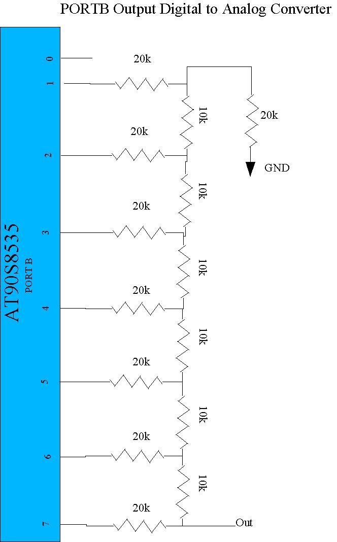
The 8-bit DAC is a simple resistor ladder attached to PORTB and does not provide a high degree of accuracy due to the tolerance of the resistors. However, it is functional enough to perform the functions necessary for this simple stand alone device.
When the waveform is started the AWG runs through an initialization process which sets up the waveform so that it's samples can be output to PORTB in a timely manner when the AWG is sourcing. In order to accomplish this values are stored in registers to minimize the number of accesses to SRAM. The length of the wave to be sourced is loaded and stored to a local register. Then the frequency is loaded and used along with the length to compute the number of clock cycles between samples. Since the 8535 is running at 4 Mhz there are 4,000,000 (0x3d0900) ticks per second and the equation for the number of ticks per sample is:
0x3d0900 / (length of waveform) / (desired frequency)
This operation requires a 24 bit by 16 bit divide which is done using code from the previous lab. This code provides the precision necessary to create an accurate frequency. The resulting lower 16 bits are loaded into timer1's output compare register A which allows the MCU to accurately space the samples. However, since the output compare register is only 16 bits the minimum frequency of the AWG is 61 Hz per sample. After the frequency is placed into timer1 the first data sample is loaded from RAM into a register and another register is set to point to the next sample to be output. Finally the timer is started and source mode is entered.
In source mode the AWG loops endlessly until an interrupt occurs. The interrupt could occur either due to timer1, in which case a new sample needs to be output, or it could be due to timer0 which controls the keypad checking for a user termination signal. The timer0 interrupt occurs once every millisecond, but only decrements a time-out register which is initialized to 30. Once the 30 milliseconds have been counted the keypad is checked for a pushed button and the command mode is entered if D is being pushed.
The timer1 interrupt first outputs the currently stored data to PORTB and then loads the next value to be output from RAM. Because the keypad checker uses some of the same registers as the timer1 interrupt routine the routine is a bit long thus limiting the maximum frequency of sourcing a sample. I'd estimate that the interrupt will take about 40 cycles so safely (assuming 50 cycles) the AWG can operate at 80 kHz per sample maximum.
Design Results
The AWG is limited by a minimum sample frequency of 61 Hz and a maximum of about 80 kHz. This means that for a 16 sample waveform the frequency must be between 4 Hz and 5000 Hz. As the number of samples increases this range moves closer to zero and decreases in width. Obviously this means that faster waveforms should use a small number of samples while slower ones use larger numbers of samples.
Ideally the voltage output from the DAC should range from 0 to 5 Volts. However, in practice the waveforms have varying peak-to-peak voltages depending partly on the sample frequency. A 4-bit square wave at 1000 Hz (sample frequency = 4 kHz) exhibits exactly 5 Volt pp operation, but a 2-bit square wave at 50 Hz (sample frequency = 100 Hz) is 5.44 Volts peak-to-peak. Furthermore the 2-bit wave is not completely square. It appears that some capacitance loading is causing the waveform to vary beyond Vcc when the sample frequency is low. On the other hand, for a 16-bit sine wave at 1000 Hz (sample frequency = 16 kHz) Vpp equals 4.91 Volts. It appears that the DAC is no where near ideal (not surprising) in dealing with the output from PORTB.
The frequency generated, so long as the sample frequency limits are adhered to, has no detectable (to the computer's scope card) error although presumably there is some associated with the granularity of the timer match register. However, since the full 16 bits of the match register are utilized and the timer is not scaled from the main clock the amount of frequency error has been minimized.
Possible Improvements
The design of the AWG was limited partly by time which necessitated the use of code from previous labs which limited the way some of the parts of the AWG were implemented. The timer1 interrupt routine could be trimmed down quite a bit to provide less limitations on the maximum sample frequency. The minimum sample frequency could also be decreased by using a status register to count timer1 interrupts allowing samples to wait more than 65536 ticks before outputting.
The user input system is also less than ideal. The menus could be implemented more cleanly so that there is a generic menu data type which can be loaded from Flash to specify each menu's contents while a state variable is used to indicate which menu the user is currently in. As it stands the AWG does not need this versatile menu system, but any additional menus would make the system easier to implement and control.
May 8,2000
Appendices