m o t o r c o n t r o l |
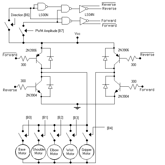
We originally had thought that the best way to control the motors from the microcontroller was by using an h-bridge and a logic circuit of nand gates and inverters so that there would be 7 signals in total for the microcontroller: Pulse Width Modulation (the amplitude), direction of the selected motor, and 5 signals for the 5 different motors to control.
This proved difficult to work with, and a lot of problems we found (much) later were caused by low current on portB (arg!!) that could not drive the relays properly. So some of the motor controls had to "share" pins with the keypad on portC. More pins would have been nice, but we managed the best we could with what we had.
Below is the schematic for our first motor control circuit. When PWM and Direction are both high, the motor selected spins clockwise. When PWM is high and Direction is low, the motor selected spins counterclockwise. When PWM is low (amplitude = 0), no motors will move.
We modified the control circuit to just a long train of relays, and things began to work a lot better! It was too bad we wasted a lot of time with the h-bridge, because it probably wasn't the best thing to work with in our case. Here was our new circuit:
