Every basic gaming system has a number of integral pieces. Firstly, there is the hardware, consisting of an input subsystem, an output subsystem, and processing logic that determines how the input effects the output. The software pieces include the game engine itself (an implementation of the rules of the game), and the two sets of drivers that interface with the input and output subsystems. These pieces will be explained in greater detail under other sections of this documentation.
Given the complexity of the game engine and the high probability of
generating bugs in assembly language, we made the decision to stick with
C programming (using CodeVision). With a bit of investment in training
with the C compiler, we were confident we could write the engine without
any great difficulty. The flexibility of writing in-line assembly
would also allow us to embed I/O drivers directly into the software itself.
The one great drawback to using C was the memory overhead that was required
to make a structured programming language work. This meant that we
had to be very careful with our RAM usage, and even more considerate of
the limitations of the hardware (execution speed and instruction count).
So basically, we used drivers we wrote ourselves to interface with the
SNES Control Pad and the T6963C LCD Controller, implementing the functions
we thought we would need. The rest of the game structure was planned
around these function abstractions. We also knew that we could not
depend upon getting an STK-200 board with the AT90S8535 on board, since
so many other groups were using them. We tried to make our code as
light as possible, and without the need for any board or microcontroller
dependent hardware. That meant no multiplies (only shifts and additions),
frugal usage of on-board RAM, and heavy utilization of the VRAM on the
LCD to hold information on the game state as well. More will be outlined
on these topics later.
The main data structures we used in our game are as follows:
A List of Directions (describing how the snake has
moved)
The basic structure of our game engine looked like the following:
While true {
Collision detection was handled by checking the VRAM, since we did not
have enough RAM on-board to maintain a completely internal game state.
Since both the LCD and the SNES Control Pad had their own controllers, writing
drivers was a matter of writing the signals expected by the interface and then
reading the values the controllers sent back. The SNES Pad utilized a
simple serial interface, while the LCD used a parallel communication scheme
that was much like the LCD we used in previous labs. We chose to use Port
D for LCD control and Port B for LCD data because of wiring issues. Port
A was set to interface with the Control Pad, and Port C was wired to the LEDs
for debugging.
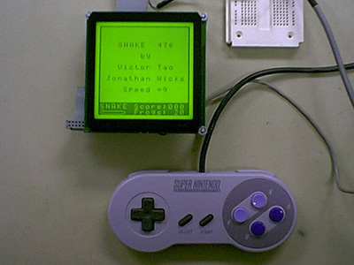
The Control Pad
We wanted to use a control pad rather than build our own hardware, both
to show that we could make use of available standard components (including
the buttons) and because we wanted proven packaging for the controller.
The Control Pads we investigated generally came in two flavors. Analog
controllers used potentiometers to generate the analog voltage signal readable
by an ADC. Digital controllers allow for reading combinations of
the 4 cardinal directions, by generating a digital signal suitable for
any digital port to read. Digital controllers also tend to debounce
their own buttons, because they must tell the system exactly what the state
of each button is. Since the microcontroller would be busy handling
the game engine, we did not want to worry about debouncing the buttons
on the controller.
Upon examining several options for controller devices, we settled on
the SNES Control Pad because we were able to find detailed information
on the communications protocol it used. Debouncing was handled internally,
and the timing issues of the serial interface appeared simple to accommodate.
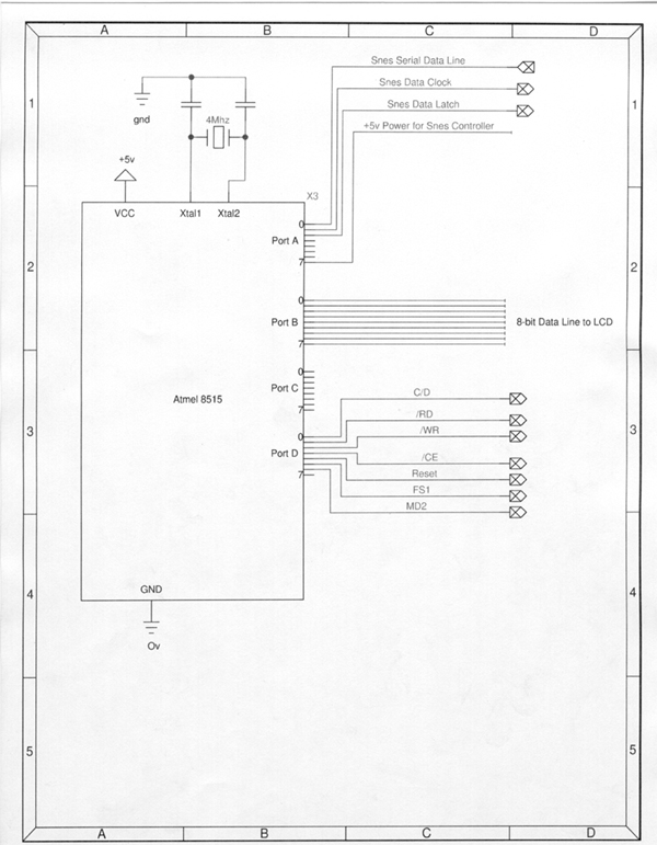
The Controller has three data pins, a +5V power and a ground. Power
was drawn of Pin 7 on Port A by setting it high, while ground was connected
to Pin 9 (GND) on Port A. The other data pins, Serial Data, Data
Clock and Data Latch were set to Pins 0, 1, and 2 on Port A, respectively.
A signal high on the Data Latch bit for a 12 us interval signals the controller
to start sending data. A sequence of 16 pulses (6 us high, 6 us low)
clocks out the serial data (8 buttons + 4 directions + 4 unused signals)
on the Serial Data line. The serial data is negative-edge triggered.
Obtaining the input was a matter of precisely timing in the code used to
manipulate the 3 control/data lines. Further detail on this topic
can be found in one of the links at the end of the project documentation.
The LCD
We had originally considered using the 240x128 LCD that was available
in the lab; unfortunately, that meant we had to compete for LCD usage time
against the two or three other groups planning on using it. Furthermore,
the resolution on the LCD was not quite what we wanted in our display.
After some browsing, we decided to purchase a 128x128 LED-Backlit LCD from
the manufacturer of the other LCD (Micro Electronics in Santa Clara, CA)
because of the Controller it came with the T6963C Controller from Toshiba,
the backlight option, and the price point ($65). Since one of the
projects last year used an LCD with the same controller, we figured we
could draw information and experience from it. Furthermore, besides
Micro Electronics, we could not find any distributors (or manufacturers)
really willing to part with just one display.
The LCD interface consisted of two pins for the backlight, and a 20
pin connector for the LCD itself and the Controller. Essentially,
we were dealing with three subsystems here: the Backlight, the LCD
itself, and the control logic for the LCD. Each one had its own power
requirements, which made wiring the LCD very hairy business. To complicate
things, the documentation was shoddy at best, requiring several calls to
the company, a pound of educated and inferred guesswork, and a half a pound
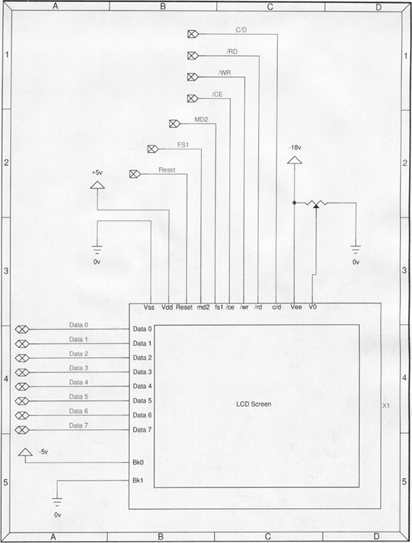
of luck. After everything was said and done, we wired Vdd to Ground,
Vss to a +5V regulated lab power supply, Vee to a 18V supply (via [2]
9 Volt Duracell Batteries), Vo to a trimpot to allow for contrast adjustment
(from 18 V to 0V), and the +5V backlight power to the regulated power
supply. To complicate things even more, the current draw on the backlight
was 380 mA, meaning that the only readily available power source suited
for the task would be pushed close to its 500 mA fuse limit. Power
to the logic was provided through Vss and Vdd, and Vee and Vo are used
to drive the LCD.
The other pins to the LCD were split between Command and Data pins.
The datapath was 8-bits wide, fitting snuggly into the Port B connector.
The Pins on Port D were set up to correspond with the 7 control lines on
the LCD: `RD, `WR, C\D, CE, `RESET, MD2, and FS1. All of these pins
directly fuse with the corresponding pins on the T6963C. `RD and
`WR were used to control the read and write cycles of the LCD controller,
while CE was used to signal the controller to get ready for communication,
and C\D determined whether the controller should look at the data lines
as command or data (command = high, data = low). `RESET was set high
only when we wanted to reset the system (during power on). We followed
the recommended procedures for initializing, reading data, and writing
commands and data, outlined by resources another company had placed on
the web (again, refer to the links below). All of drivers were written
in Assembly language (to allow for simple bit manipulation), so we had
to pass parameters back and forth to the C code, through the stack and
registers.
With a 20-pin connector (not useable with the lab breadboards) and power
lines intermingled with data and command lines, hooking up the entire assembly
to the regulated power supply, DC power, and two ports was no simple task.
The fact that the LCD still works is itself a testament to its durability;
we have hooked it up backwards, reversed the polarity of some of the connections,
even had to deal with documentation that was inconsistent with the original
specifications found on the web site. We finally decided on using
a 40-pin ribbon cable (we couldnt find any 20-pin ones) with braided wires,
splicing off the power connections and soldering them to solid wires connecting
to power. The data and command cables were wired to 10-pin connectors
we found in lab.
The Microcontroller
The last system we had to worry about was the code for the game engine
itself. With the drivers for the other subsystems in place, it was
a simple task to write some utility functions to put a pixel on the screen,
or to place a character somewhere, or to clear the entire screen, etc.
We ended up starting from ground zero, and iteratively writing and testing
code (to minimize bugs). Much time was spent on considering what
data structures to use; we had access to only 256 bytes of ram on the 4414,
split between the hardware and software stacks, as well as our global variables.
Possible upgrading to an 8515 would mean double the RAM, but we still had
the overhead taken by the hardware and the C code itself. Needless
to say, efficient use of RAM was top priority. Flash program memory
was used somewhat more liberally, mainly because our control of the Flash
RAM usage was restricted anyway (because of the C compiler).
Basically, we jammed everything that could fit into bytes, and for variables
that would waste more than one bit of the byte (like the cardinal direction
0 to 4), we packed multiple pieces of data into the byte, and did some
bit masking to access the data we needed. For example, to store the
direction of the snake (every bend and twist we had to go through), we
knew we would have at most 256 sections of snake to deal with, each one
oriented exactly one of 4 directions from the next. If each section
were a byte, we would need 256 bytes to store the entire data set.
Since there are only 4 directions, we only need 2 bits out of each byte
to store the data, so we pack in the data from 4 segments into each byte
(there are better ways to do this, but more complex instructions would
be required to decode them). Our data structure size then drops from
256 bytes to 64 bytes not exactly lightweight with our RAM restrictions,
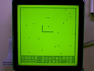
but at least it is guaranteed to fit. We also used the VRAM to help
store system state instead of tracking objects for collision detection
in the internal SRAM, we used the VRAM to keep track of the collisions.
All access to the LCD was through the utility classes we made setting
and getting pixels and the text. As for the other two large data
structures (the 3-character isApple array and the 40-character 2x20 apple
array), isApple tracks which frogs have been consumed and which have not
each bit represents the state of each frog; apple represents the position
of the frogs on the screen (the reference to apple is a misnomer; they
were apples in the original game, but since they can move, weve renamed
them frogs).
For this game, weve also implemented a shift register random number
generator to determine the initial placement and the dynamic movement of
the frogs. The code for the random number generator is small and
exceedingly fast, which is perfect for our uses. The seed is set
when the user presses start at the startup screen we run a timer that
goes at full clock speed until start is pressed; this gives a good psuedo-random
seed to start with. A small problem with correlation does occur between
each successive call to the function, but that cannot be avoided; only
hidden (this is because of the shift-register). For example, in the initial
frog placement, if we place the frogs one at a time on the display (x and
y), we tend to have the frogs on diagonal lines. If we instead place
all of the x values first, then all of the y values, the problem does not
show up.
Random movement of the frogs is a two-step process. First, we choose
a random number each time the game engine evaluates itself, and test the number
against a constant. We move the frogs based on the probability that the
number we choose is less than a constant number. Then we choose random
directions to move in by obtaining another random number and feeding random
bits from it into a function that will give us the direction to move in.
The frogs then move unless they are blocked (check the VRAM).
The controller was not to bad to setup. The specs for the controller
were not difficult to find on the web and the timing for the controller
didn't seem difficult. The controller responded without any problems. It
actually made an excellent way to control our game since it required no
debouncing and it detected key presses very accurately. The signals that
the controller sent back to us were clean and easy to detect digitally
on the port pins. We never had any problems with noise or false key presses
which we were initial concerns we had when we chose to use the SNES controller.
We were also quite worried about using C instead of assembly. We were afraid
that by using C we would slow the program down too much and that it would create
code that was too large to fit into the flash memory. Another issue with using
C was the fact that we had to worry about how much space our global and local
variables could use. If the variables became too large for the memory they could
potentially stomp over the stack. Ultimately all of these worries turned out
to be for nothing. The speed of C was not a problem at all since we used assembly
language for all of our low level hardware communication, such as the LCD functions
and the SNES controller code. With some carefully thought out data structures
we were able to store quite a bit of information about the snake within a small
amount of memory. Overall, I am glad that we choose to use C to create out final
project. It greatly helped us to create a coherent structure for our code and
it made debugging quite a bit easier. With a program this size it helped to
be able to use C constructs to simplify implementation. The only real problem
we had with this version of C was that at certain somewhat random times we would
get "relative branch out of reach" errors when the assembler compiled the assembly
file that C generated.
We don't have any real regrets about the project. It would have been nice to
have talked to the people who sold us the LCD in order to learn more about the
LCD before we tried to hook it up. If we had more time we would have liked to
have added sound to the game. The addition of sound wouldn't be too difficult
and would allow for a more enjoyable game experience. We also would have liked
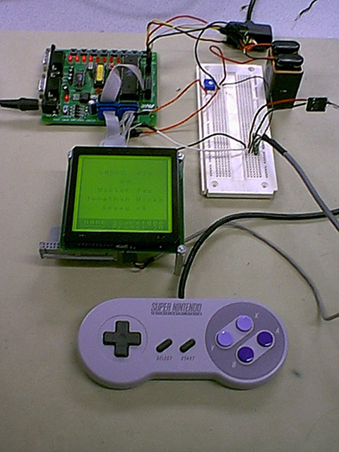
to package the entire project up into a handheld device. This can easily be
done by removing the Atmel chip from the development board and soldering the
connections directly to the port pins. Both the LCD and the Atmel chip could
be powered from batteries. We probably wouldn't be able to use the backlight
since it draws too much current. The entire project could easily end up being
about the size of a Game Boy. It also would be nice to add external memory so
that we could store game levels, which would greatly enhance the gameplay. All
in all, we were very pleased with the way things turned out.
High Level Design:
Flow chart of Design
A List of the Frog positions
A List of Flags to show which frogs have been consumed
A byte to hold the score, and to hold the timer
Initialize state of the game
While true {
Read Input from controller
Process the Input
Move the frogs
Update the LCD Output
If (game over) then break
}
}
Program/Hardware Design:
As mentioned before, we split our project into several sections, both in
hardware and software. What occupied us for the first two weeks was
procuring the hardware we needed and creating the interface and drivers
required to utilize them.
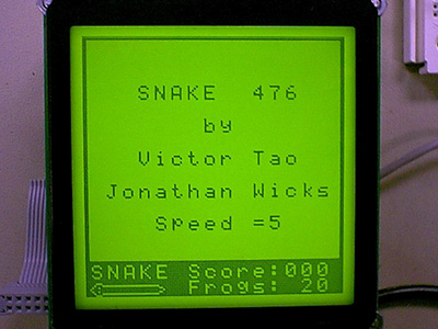
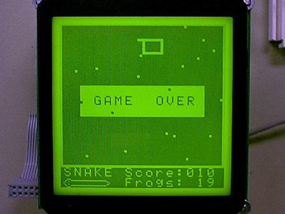
Results of the Design:
Overall, we are very pleased with our final result. The game responds very
well to user input and the snake speed has quite a bit of room to be sped
up if needed. At many times during the project it seemed like we were never
going to get some of the hardware working. In particular, the LCD screen
caused us quite a bit of grief. The documentation provided by the manufacturer
was poor and incomplete. The pins on the documentation didn't even match
up with the pins in the documentation on their web page. We spent a good
portion of the time on this project trying to get the LCD to respond. Luckily
we were able to find a web site which provided us with enough information
about the T6963C controller for us to be able to work through the problems.
What we would change next time:
Appendix:
Download the code
Oscilloscope Output of SNES Controller Signals
Schematics:
Pictures:
The following are some helpful links to datasheets and FAQs that helped us
along the way:
CodeVisionAVR C Compiler - The compiler
that made this project possible
Information
on the protocol for SNES controllers
Densitron
- They had quite a bit of information about the T6963C controller which
came in handy
MicroElectronics - This is where we
purhased the LCD, they had some documentation about the LCD