![]()
![]()
![]()
![]()
![]()
![]()
|
|
|
| Home AutomateDocumentationcorrect as of 4th May 2001
Andrew Chung (ac111) Chee Yong Lee (cl140)
IntroductionHome Automate is a low cost micro-controller based network developed as a final project for EE 476 at Cornell University. Through a user friendly interface, the user can monitor the security status of his home and schedule the activation of various appliances remotely over the normal TCP/IP connection from anywhere of the world.
ObjectiveThe objective of our project is as follows.
MotivationInstead of concentrating on a single device control, we feel that it will be fun and rewarding to put together a network of devices that can effect other devices on the same network. A home automation project is the ideal choice as it deals with a variety of hardware. High Level Design Overview
Remote ClientThe remote client is a java based program that we have written that utilizes UDP(user datagram packet) socket to communicate with the MCU Controller. It works through any IP (Internet Protocol) based network like ethernet and Internet. All it needs to set up a connection is the IP address of the MCU Controller which is known in advance. MCU ControllerThe MCU Controller is a server process that runs on a PC connected to the Hub using a RS232 serial interface. The baudrate is 9600bps, with no parity and flow control. Written in Java, this MCU Controller can reside on most common platform from Unix, Linux, Macintosh to Windows. HUBThe purpose of the Hub is to act as the router that directs the relevant packet to and fro the managers and the PC. It parses the content of the packet before deciding on the path to route the packet to. Manager A/B/CThe manager deals with the actual I/O interactions with the devices that are connected to the port. The connected devices can deal with any of the thermometer, fan, light and alarm on any of the port A/B/C without reprogramming. This flexible structure allows us to swap the devices around, with changes done only to the PC MCU Controller. AlarmWe have a little buzzer that runs directly from the port output to simulate the workings of an alarm system. The alarm can be activated from the remote client, triggered by the thermometer or even runs on a schedule. FanThe fan we use in this project is a small CPU fan that taps its power from a 9V battery. This fan can be activated through remote interface or a regular schedule. ThermometerThe thermometer utilizes a LM34 chip to detect the variation in temperature. Through an amplifier circuit, the voltage from LM34 is then sampled by the micro-controller to determine the temperature of the room at any particular time. Light ControlThe light control is a light dimmer that takes in input from the PC on when to turn on and when to turn off. This interface allows the user to set the target brightness with the specification of the time interval.
Implementation DetailsData CommunicationThe most challenging part of this project is to come up with a flexible and yet efficient communication link from the client all the way to the actual physical devices. Below is a detailed explanation of the steps we employed to achieve the communication task. Communication between Client and Server The client communicates with the server through UDP packets. Each packet is tagged with a header that identifies the type of the packet. Also, each packet from the server to the client contains the current time on the server. The data portion of the packet is basically serialized versions of the objects used to model the devices. Each object has a method (toBytes()) that turns it into a byte stream, and the super class (I_node) has a factory method (make()) that turns the byte stream back into objects. When the client starts up, it will query the server for the list of connected devices. Control panels will be created only for devices that are connected. Communication between Server and Hub The server communicates with hub through a serial connection. We used the Java comm API to send and receive data from the serial port. The data sent is a numerically encoded instruction that the hub will then direct to the correct manager. DownlinkEach packet of data from the server is of following format (18 bytes):
MM - Which manager to forward packet to AA - Device ID for the device to control ZZ - Command BB-GG - Data UplinkThe format for packets from the hub to the server is similar. There is no MM field. The command field (ZZ) now identifies the kind of data that is being sent back. Communication between Hub and Manager
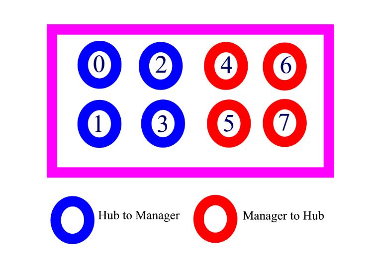
We allocate one port for each manager on the hub. Hence we can hook up up to three physical manager on the same hub. Within each port, 4 bits are used for uplink and 4 bits are used for downlink. The bit patterns are as follows: F - No data A - Nibble separator 0 to 9 - Data B to E - Unused The default state of the four bits (either uplink or downlink) is at F. The nibble separator is used to separate the bits. The receiver end samples the line at 4 times the rate of the transmitting ends so that it will be able to pick up any change been made by the transmitter. This setup allows us to do away with any clocking signals or timing synchronization. For a low baud rate application like this, this simple arrangement allows full duplex communication to allow simultaneously. Downlink: Each packet of data from the hub is of following format (16 bytes):
AA - Device ID for the device to control ZZ - Command BB-GG - Data Uplink: The uplink data format is the same as the downlink format, where ZZ now identifies the type of data being sent. Role of the HubThe hub forwards packets from managers to the server, and routes packets from the server to the correct manager. It has limited intelligence in that no routing information is kept locally. The first two bytes of data from the server is stripped off, and the rest of the packet is forwarded to the target manager. Due to memory size restrictions, we've allocated enough space to hold exactly one packet. If too much data is sent from the server, the hub will flag an overflow and reset the buffer. This ensures that communications can continue even after an error.
Hardware DesignWe choose to use the following hardware for this project.
The hubs and manager are chosen in this manner as both of us happen to own a STK 500 development board each and we are allowed to use one STK 200 board from the lab.
Software OverviewThe micro-controller code is written in C using CodeVision. No assembly coding is required. For the Client and Server, we use Java JDK 1.3 for its high portability to various platform and its extensive set of API. In particular, we make extensive use of Java Comms API that enables us to do serial communications without going all the way to the bits and bytes level.
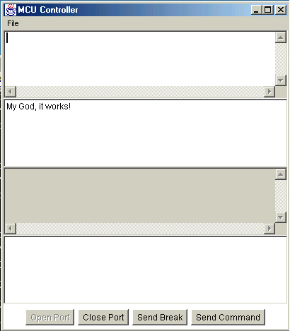
Screen Capture and Achieved ResultsServer ProgramThe server program which we termed MCU_Controller is the interface between the client and micro-controller. New devices can be added in by just extending the current set of classes. At the moment, it performs the following tasks:
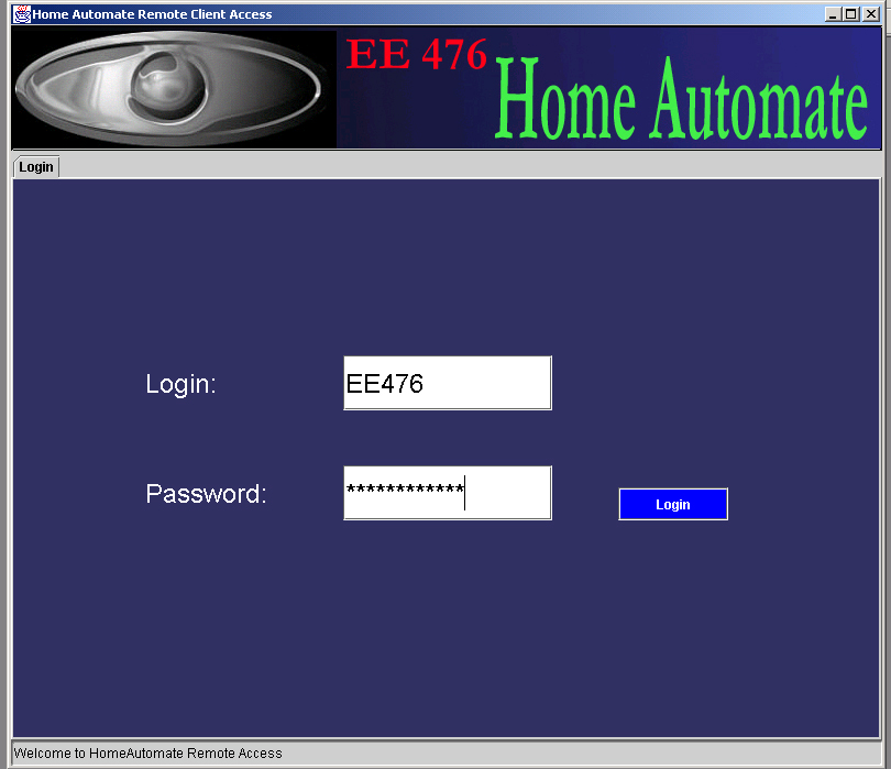
Client ProgramLogin Panel controls the access to server. Before the client program can gain remote access to a whole arsenal of devices in the house, a login system is required to authenticate the user's identity.
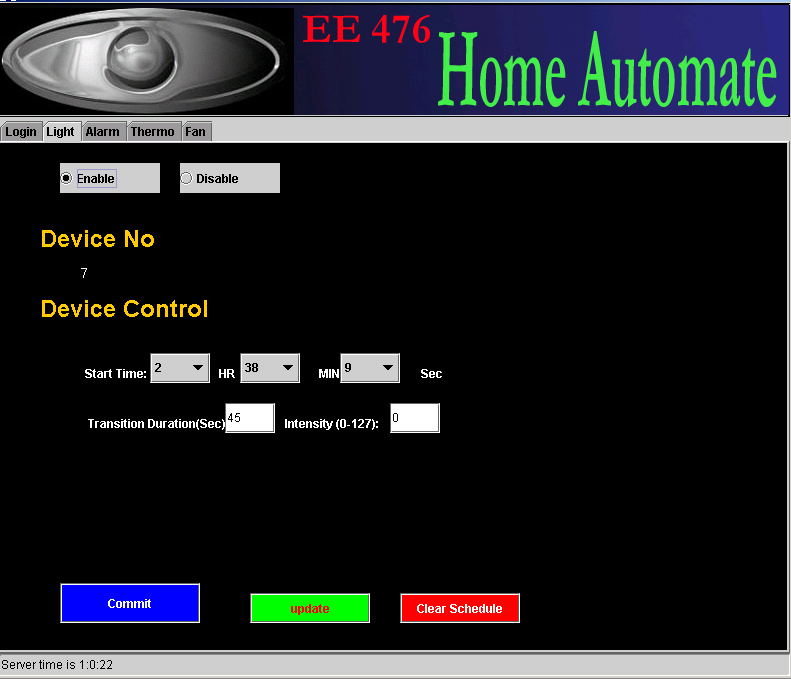
Light Control Panel allows the user to control the lighting by specifying the onset time, transition duration and light intensity. A schedule for the whole day can be setup by committing the settings to the server. Clear Schedule button will empties the existing schedule buffer. Such a setup allows users to turn on and off a lamp gradually by specifying the start time of the action and the intensity value it is supposed to achieve. The transition duration can be achieved with an accuracy of around 10%.
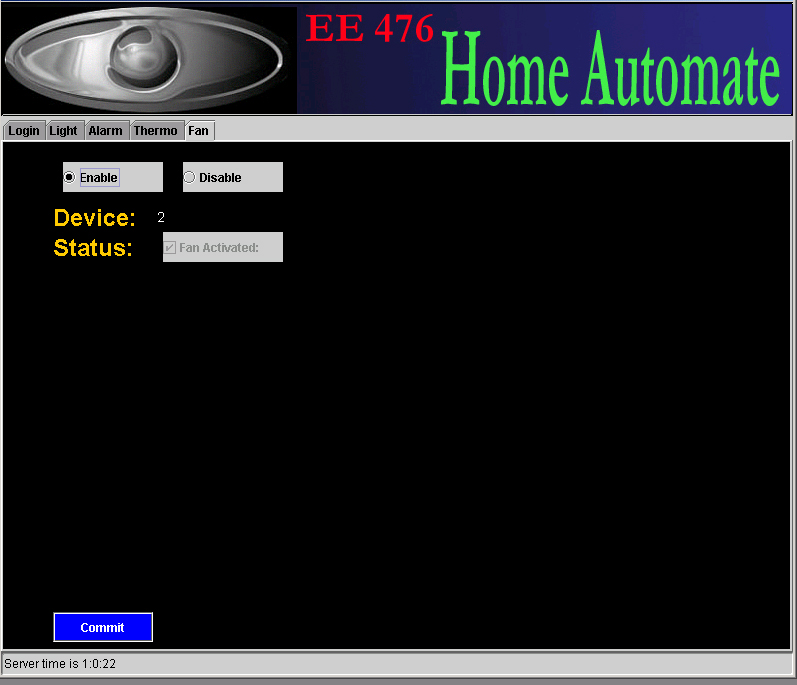
Fan Panel is a simple screen that allows the user to toggle the status of the fan.
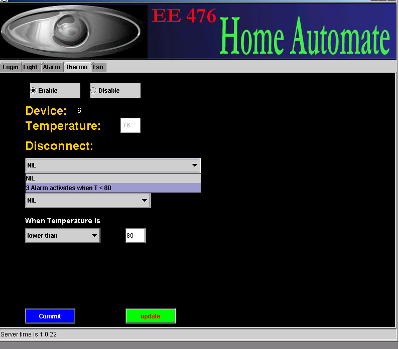
Thermo Panel is the interface for the thermometer. It allows user to get the most updated temperature of the house, and sets up special triggering conditions for all the currently connected output devices, irrespectively of where this device is situated on the network.
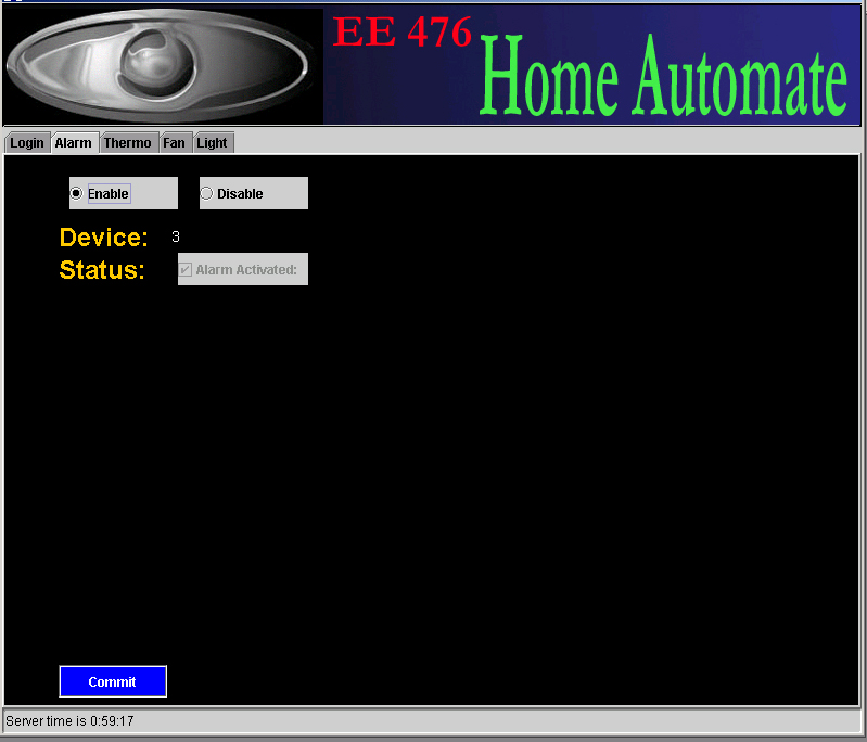
Alarm Panel is a simple screen that allow the user to activate/deactivate the alarm system.
What you would do differently next timeWe were overly ambitious in our proposal, and went about implementing a lot of high level designs and scalable architecture before performing the underlying communication tasks between the micro-controllers. We feel that a bottom up approach instead of a top down approach is more applicable in this context. Communication within the micro-controllers poses the biggest headache for us, as we have to design our own interface protocol. We would have use special Integrated circuits to perform the communication among the micro-controllers instead of design our own untested ideas if given the opportunity in the future. We spend a lot of time soldering our circuits onto the prototype boards only to realize later that they do break down, almost as easily as the bread-board ones. Thus, we will definitely do most of circuits on breadboard next time to save on valuable development time. Initially, we wanted to have an interface that can be run as an applet. However, most of the current browser do not support JSWING objects yet, and as such we could not run the Java application we created on a web browser. An alternative solution to this is to use the standard AWT(Abstract Window Toolkit) library. Also, we would not have purchased the STK500 board if we had known how much trouble we'll have using them. They are a lot slower than the STK200 to program and we spent more time trying to get it to work than we should have. ConclusionThere are a lot of unforeseen problems that happened in the course of the project that requires us to have an acute intuition of where is going wrong. After much persistence, we managed to present a working, but scaled down, version of the original HomeAutomate system that we envisioned when writing the project proposal. The fundamental communication links are set up and developing more devices to the set of HomeAutomate architecture is relatively a simple thing. Our current network can serve as the starting point for a much elaborate and extensive home automation system, Appendix with listingFor a listing of our source codes, please look under the Archive Section of this site. Appendix with schematicsThe connection of the Hub to the two managers is as shown in the high level overview. Right now, we only use two managers because of the restrictions in the amount of hardware we have and the number of devices we need to hook up. Manager A to Fan and Buzzer
Manager C to Light control and Thermometer
AcknowledgementsNot in any special order, we will like to thank the following people and companies that make our project a reality:
|
EE 476 Micro-controller Design
|

 .
.