Sensors
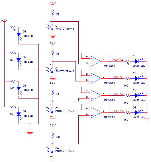
In order to detect where the train was on the track, optical sensors were placed at four points on the track. Each of these sensors was an infra-red (IR) emitting diode and photo-transistor pair. The sensors output a logical 0 when there was no train present and a logical 1 while the train was breaking the beam. This was accomplished because the LED constantly emitted a beam into the optical base of the photo-transistor, so the transistor was on except while the beam was being broken. The output of the transistor was buffered using a Burr-Brown OPA2350 op-amp, and then connected to both the port pin on the Atmel 90s8515 (PORTA[0..4}) and to 4 green LED's to allow us to visibly ensure the sensors were working properly.. Schematics showing the wiring for the LED's and photo-transistors are shown in figure 1 below.

Figure 1: Diagram of Sensors for the Train
AC Motor Control
Controlling the speed of the train us the 90s8515 was accomplished through the use of an h-bridge scheme of transistors. This indicates the AC motor is controlled by four transistors, with only two opposite ones turned on at any time. One must be careful to not turn on two transistors on the same side, else some components may be blown due to excessive current. The discrete logic shown in figure 2 was used in order to ensure only proper signals could be sent to the H-bridge. The F/R control allows for one pin to control the direction of the train, 1 for forward and a 0 for reverse. The PWM input is the output from the pulse width modulator (PWM) from the 90s8515. This allows control of the train using only two pins. The outputs from the logic are the inputs indicated on the H-bridge in figure 3.

Figure 2: H-Bridge Controller
In order to get an appropriate gain out of the TIP31 and TIP32 power transistors, a Darlington pair was assembled using 2n3904 and 2n3906 transistors and show in figure 3 below. To ensure no noise could feedback from the noisy train 17V power supply, 4n35 opto-couplers were used, and the grounds were separated with an inductor (not shown) and a 50 micro-farad capacitor (not shown) was placed across the terminals of the trains power supply to reduce the noise emitted.

Figure 3: H-Bridge
Attaching all of the parts to the 90s8515 completes the hardware design. In figure 4, the pins for the motor control and sensors are shown. Pushbuttons are added to manually control the train as it moves around the track. Not shown on this schematic is the UART control, which is from PORTD[0..1]. This is where the train will receive programs and instructions from the computer. Also, the programmer for the chip is not shown. This is a 10 pin header connected to pins on the 8515 for on-board programming.

Figure 4: Atmel 8515 Connections
The LCD (not shown) is connected to PORT C of the 8515, and the connections are listed in table 1:
|
Table 1: LCD connections |
||
| 8515 Pin | LCD pin | Functionality |
| Ground | 1 | Ground |
| Vcc | 2 | Power |
| N/C | 3 | Contrast |
| PC0 | 4 | RS |
| PC1 | 5 | RD |
| PC2 | 6 | Enable |
| PC3 | 11 | D4 |
| PC5 | 12 | D5 |
| PC6 | 13 | D6 |
| PC7 | 14 | D7 |