EE476
Final Project
AT90LS8515 PBX (Private
Branch Exchange)
by
Paruj Ratanaworabhan
(pr57@cornell.edu)
Jintadhee SUDASNA
(js295@cornell.edu)
Introduction
In this project, we demonstrate the 4 line telephone systems with full signaling and switching functions similar to those of the central office systems. Dial tone, busy tone, and ring tone are provided during call progress. Ringing is generated at the receiving end of the phone being called. Switching employs integrated circuit (IC) matrix switches on four buses. Thus, this system is expandable to 8 lines (4 pairs) if more hardware is added. This system is switching on the Dual Tone Multi Frequency (DTMF) dialing signal and does not work with pulse dialing signal founded in some older phones.
Motivation for doing this project
We were looking for a project, which offers a balance between software and hardware. Telephone switching came to our mind after we first considered X-Y plotter. The latter, however, is rather involved in mechanical hardware, neither of us has really had experience on. So, we opted for telephone switching where the hardware involved is electronics in nature.
High level design
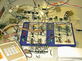
The telephone systems we built consist of the phone line interface circuits and the MCU on the STK2000 development board.
Each phone line interface circuit has the following hardware.
- Ringer
- Hook switch relay
- Tone frequency generator
- DTMF receiver
- IC switch
The four phones share a common ringer; for all the other components, each phone has its own individual. This is primarily due to the wattage rating of the ICs, we use.
The MCU on the STK2000 is the central brain of the systems, whose embedded software provides the control functions to each of the phone line interface circuits connected to it. PORT-A is used as the address bus, which, via decoding logic, provides the enabling signal to appropriate functional units. PORT-C is used as the data bus that read and/or write data to those units. PORT-D is reserved for UART. Initially, it is used for debugging during systems start-up. It can be modified to provide the central monitoring function for the entire systems.
All communication to the functional units via the PORT is asynchronous and level enable.
Program design
The embedded program in the MCU that provides the control functions cycle through the state machine shown. (Receiver, Sender#1, and Sender#2)
Timer 0 is used to provide a time base for polling each phone. It is set such that each phone gets serviced every 40 ms. Note that this is more than adequate for phone state update as a human typically press a dial button for more than 100 ms before releasing it.
The busy tone and ring tone cadence can be change at #define at the beginning portion of the program.
The number assigned to each phone can be increased if we expand the states after CALLEROFFHOOK to cycle through a number registration state machines before moving on to CHECKRECEIVER.
The switching scheme is such that the sender acts as a master to the bus to which it is assigned. When a receiver is available, the program switches the sender on its bus and forces the switch on the receiving end to switch on the same bus.
We use a scheme, which the receiver is the full slave of the sender. The receiver state after RINGING is completely determined by the sender. The receiver is able to return to IDLE after RINGING and RECTALKING (receiver talking) only when the sender has returned to IDLE. This is done to reduce the overall states and signaling and, hence, simplify the programming and the required hardware.
Hardware Design
The main circuit for this project is “Phone Line Circuit”. The Phone Line Circuit(s) are connected to Micro Controller, Decoder, Ring Generator and Telephone. Micro Controller sends or receives data via Share Data Bus by PORT-C and sends address to the decoder by PORT-A. The decoder receives the address, decodes the address and sends the control signal (Control Enable and Control Latch) to each Phone Line Circuit as shown in overall system diagram. The Phone Line Circuit(s) communicate with MCU by sending or receiving data via Shared Data Bus. MCU uses time sharing protocol to control each Phone Line Circuit by sending the address of the Phone Line Circuit to the decoder and sending control data to Phone Line Circuit via Data Bus.
Each Phone Line Circuit is connected to one telephone line. In this project, there are 4 Shared Audio Bus so we can expand the switching up to 8 lines.
The Phone Line Circuit supplies DC voltage to telephone. It receives signal from telephone, check the number by DTMF receiver and send the number to MCU when requested. Tri-State buffers are used to multiplex data from DTMF receiver and Off-hook detection relay of each Phone Line Circuit to Shared Data Bus. Tri-State buffer passes through the data when it receives Control Enable signal from Decoder. Because we use time sharing method the control signals sent from MCU to each Phone Line Circuit will be latched when the Phone Line Circuit receives Control Latch signal from Decoder. There are 3 sets of control signals from MCU to the Phone Line Circuit: 1. Tone Selection, select tone presented to telephone when off-hook (Dial Tone, Busy Tone, and Ring Tone), 2. Audio Switch Control, control audio switch to connected phone line together for speaking, and 3. Ring Control, control relay switch ring signal to telephone line.
The Audio Bus is used to link each phone line together when there is calling. Coil and capacitors are used to separate analog signal from DC Supply voltage. There is one off-hook detection 2-contact relay in each Phone Line Circuit. When telephone off hook the relay will close and pull the off-hook detection output down to GND and switch the audio channel from ringing mode to audio mode.
Block diagram of the Phone Line Circuit can be shown in two sections, Digital/Control Section and Analog/Audio Section as shown in next diagrams. The circuit detail can be found in Appendix A) Schematics
Phone Line Circuit
Analog / Audio Section
Results of the design
This project can be used as telephone switching up to 8 lines. There is some noise in line because we did not have good filter in our circuit.
Next time
If we have more time, we will add some feature of this project. Current design can use only internal phone line. We can modify the Phone Line Circuit to support external telephone line calling. We want our PBX has ability to connect to external telephone line.
Appendix
A) Schematics
B) Code
C) Data sheet