Cornell University EE 476 Final Project
Fertilizer Feed Rate Controller
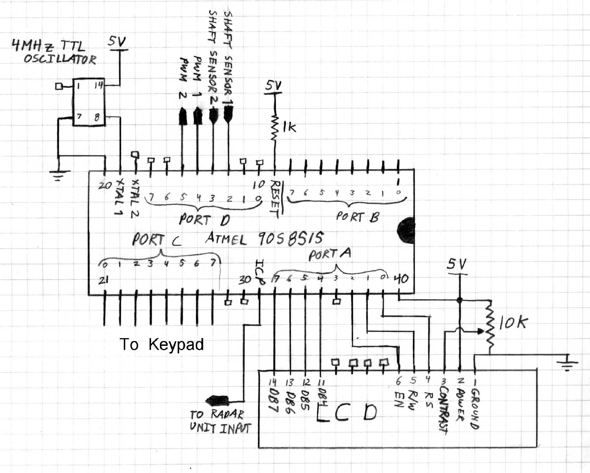
Microcontroller Board: the connections to hook up the microcontroller to all the peripheral devices.
PWM amplification Circuit: used to take the 5V low current PWM signal from the microcontroller and convert it to a 12V higher current PWM signal for controlling the heavy-duty MOSFETs that will drive the fertilizer drop motor.

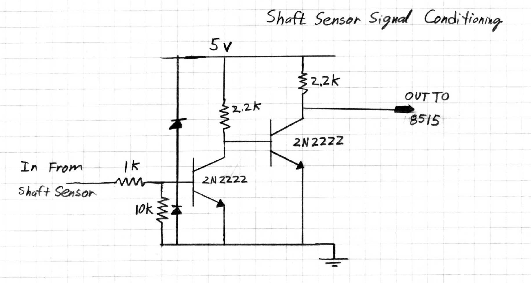
Input Signal Conditioning Circuit: Takes 5 or 12V signal from shaft sensors or radar speed sensor and converts it to 5V for interfacing with the microcontroller, and provides over/under voltage protection so that the microcontroller is not damaged.