ee476 – final design project report
Project: Club Light Controller
By: Alex Cerruti and Chris Wherry
Date:
Introduction
The first club/disco lights that flashed to the beat of the music were
invented in about 1968. A set of lamps
would flash to 3 different frequency ranges: one set in sync with the bass
signal, one with the treble, and a last set in sync with the highs. Only transistors and thyristors
and extensive analog circuits existed back then to control the lamps. It was later determined that this many
flashing lights was confusing, and had no correlation to the dance music, hence
it was quickly adopted that many lights could flash in sequence or in patterns
only to the bass channel (or the beat of the music, which is what people usually
dance to). From this point on, a whole
class of club lights and various effects were created: rotating oil wheels that projected multiple
psychedelic patterns on the floors and walls, pin spots flashing in random
sequences and colors, scanners which sweep in various directions, helicopters
which spin, dichro flowers that produced spinning
colors to the beat of the music, and so on.
Finally in 1990 Intelligent Lighting was created using the magic of silicon chips. They all work on the same principal: a beam of light is sent through a colored filter and a shape (Gobo). The beam is then projected onto a motorized mirror, which allowed the beam to be arbitrarily pointed. The beams would change color and directions based on the beat, or on a preprogrammed sequence using DMX-512 (see below for links and a discussion). Our club light is a variant one of these original Intelligent Lights.
The original owner of this club light was trying to fix it when he accidentally shorted out the original controller to 120 VAC. It was not surprising when nothing worked after that! The original board contained an Atmel 8051C chipset that performed the main functions (including DMX). The rest of the board was actually constructed using rather awful engineering techniques. For example, the stepper-motor for the color wheel was powered off of an unregulated DC voltage (immediately after full-wave rectification). That is to say, the 12-volt stepper motor was running off of a highly unstable 24 volt supply! It was no surprise the motor was overheating with the original circuit. Certainly, better circuit design was needed.
Anyhow, we decided that we needed to revive this light and get it working again. Since no schematics and no information at all can be found on the workings of the light, we decided to take it upon ourselves to redesign the entire analog to digital interfaces to the microchip. Furthermore, all the software for controlling the stepper motors (to obtain random colors), the lamp, and the muffin fan had to be created.
Objectives
- To make the club light functional again
- To redesign the power supplies for the motors and microchip
- To understand how the stepper motor controls work to make it turn in either direction
- To create an analog temperature sensor circuit to run the cooling fan
- To design and build an analog beat detecting circuit that runs off of a line-level signal (mono)
- To make the color wheel change to a random color upon sensing a beat
- To interface the microchip with the various components (stepper motor, lamp PC Relay, cooling fan, and musical input)
High-Level Design
Rationale and
Logic Structure
Certainly the most difficult portion of the project to implement was detection of the beats. Rather than relay on an ADC and complicated algorithms to calculate the beats within the MCU (using software), we opted for an analog approach. The analog approach simply takes a mono line-level music signal; low pass filters it, and does beat detection. The output of the beat detection is passed to the MCU and is assumed to be the beats of the music (for more explanation, see Beat Detection below).
After beat detection, a randomizer was created using
software. timer0
was polled every time a beat was detected, and the current timer value was
divided out by 11 and the remainder (0 to 10) was used to determine the
position for the next color (since ten colors are possible using our color
wheel). This scheme offered an easy way
to randomize the colors.
CPU
We decided to use an ATMEL 90s8515 processor instead of the 8051C or the Mega 163 series. The 90s8515 offered better speed (8 MHz) than the Mega (4 MHz) and more processing power than the 8051C. Also, this was the chip that we felt most comfortable programming with. It also turned out that the extra instruction space was not a factor in choosing our MCU because our final line count was around 250 lines! Furthermore, since all the interfacing was done using analog circuitry, no ADC’s were required. Hence, the 90s8515 was the most logical choice.
Stepper Motor
(Hardware)
We built the control interface circuits to run the 10-position color wheel, which is controlled by a 200-step unipolar stepper motor.
Stepper Motor
(Software)
The microchip also had to be coded to properly turn the stepper motors. Initially, upon power-up, the stepper motor (when facing the front of the light) has to be rotated fully clockwise until the stop-pins hit. This is absolutely required upon each power up because the microchip needs to know the initial color (black). To go to the next color (white) the stepper motor must transition counter-clockwise through 20 stops. Each successive color is 20 stops further than the previous. However, one cannot exceed 200 stops (ten colors) or the reference point is lost. Hence, knowing the initial position at startup, and keeping track of the current position, and the next position, the microcontroller can easily instruct the motor to turn the required number of stops to the next color (number of stops to turn = current_position-next_position, where the sign (±) indicates the direction to turn).
Buffers
All components that ran off of 12 volts (the stepper motor, muffin fan, and control lines for the lamp relay) were buffered from the main processor using TIP31-C’s. This offered several advantages. The TIP31-C can sink up to 1 Amp of current, which is more than enough to run each of the components. Additionally, the TIP31-C will provide a fairly good buffer to protect the ports on the microchip from the EMF spikes created by inductive loads (like the motors).
Cooling System
Another component that we felt needed upgrading was the muffin fan. The muffin fan was directly wired; hence it was always on when AC power was supplied. We felt that this was unnecessary, and would make the light cooler (pun intended) if we used an IC to detect the temperature and have the fan turn on once the internal temperature exceeded a certain point. Not only this saves power consumption on the long run, but it also flexes our analog interfacing skills. Instead of using an ADC to convert the voltages put out by the temperature sensor, we simply set a comparator to trigger at a voltage point that coincided to a temperature of 100°F (roughly).
Beat Detection
The original circuit used a capacitive microphone to detect the beats of the music emanating from the speakers. However, the microphones were incredibly sensitive and had no gain control. Hence, in moderately loud environments, the lights would simply lock up and turn off. Rather than detect a beat using logic and software, we took an analog circuit approach. The main reasoning behind this is that these club lights are generally used in conjunction with dance music. Dance music usually has a very distinct low frequency, high amplitude beat. Hence, one could easily detect a beat by low-pass filtering the left (mono) line voltage off of a CD player and passing the low-passed signal into a peak detector. Hence, every time a peak is detected, it is directly correlated with a beat. This is the signal that is then detected by the MCU. Every millisecond, the MCU would poll the port and determine if it was high. If the port was in fact high (signaling a beat), the MCU would send the appropriate signals to change the color.
Random Color
Generation
The original light seemed to be stuck in certain patterns, always choosing the same colors. In our software, we decided that we would implement the colors randomly. To generate a random number we would poll timer 0 and then take modulo 11 of the resulting number. This would output a number between 0 and 10 (0-9 colors, 10 strobe). Hence, all of the colors in the 10-color wheel are now being used.
Power Supplies
Finally, extensive power supplies were built to run the all the motors at the proper voltages. 120 VAC power was stepped down to 12 VAC using a transformer, and this voltage was then passed through a full-wave bridge rectifier. The unregulated DC voltage off of the FWBR was passed into several voltage regulators. Additionally, all the microchips’ ports were buffered from the motors using TIP-31C transistors. In the end, the entire electronic guts of the light were completely replaced. The original transformers, case, light bulb, color wheel, motor, and fans were used and interfaced to the microchip.
Hardware Design
Major Components
used:
|
LMC7111 |
“Tiny CMOS OpAmp w/ Rail-toRail Input and Output” (8-Pin DIP)
|
|
|
“Precision Fahrenheit Temperature Sensor” (Plastic Package)
|
|
|
“NPN Epitaxial Silicon Transistor”
|

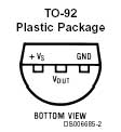
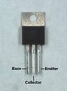
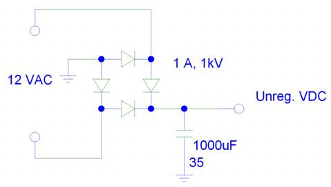
Figure 1:
Every circuit begins with the power source. In our CLUB Light, we had a conveniently available transformer that stepped the line voltage (120 VAC) to 12 VAC. This voltage was fed into a full wave bridge rectifier, and a 100 mF polarized capacitor was used to minimize the unregulated output voltage. From this point, all necessary regulated voltages were created using voltage regulators.
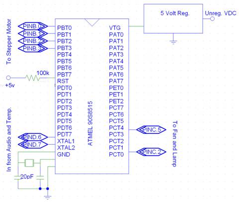
Figure 2: The Atmel 90S8515 Microcontroller Unit and its associated ports
A single 5-volt regulator
was used to power the MCU alone, for fear of mixing digital noise into the
analog interfacing circuits.
Additionally, all outputs and inputs were buffered from the analog
circuits to minimize noise.

Figure 3: The Temperature Sensor (top half) and Beat
Detector (bottom half)
The heart of the temperature sensor is the LM34 temperature sensor. It provides a linear output voltage of 10 mV/°F. The output voltage from the LM34 is then gained by a factor of 2 using the leftmost, top opamp in a non-inverting configuration. The opamp immediately following it is used as a comparator, with the trigger voltage set at a temperature corresponding to about 90°F (keeping in mind the gain of 2 from the previous stage). When the temperature of the sensor exceeds 90°F, the output of the comparator goes high (+5 volts). Finally, this signal is sent into a 2N3904 transistor, which pulls the pin voltage on PIND.7 low when the temperature exceeds 90°F, instructing the MCU to turn on the cooling fan.
The audio input receives a line-level input (typically 2
Volts peak). The very first opamp is a Sallen-Key 2nd
order

Figure 4: Fan and lamp driver interface circuits
The fan and lamp driver interface circuits are simply used to easily control these devices and to isolate the MCU from high voltages. When a high voltage is output onto PINC.2, the TIP31-C will sink current and the fan will turn. The TIP31-C isolates the MCU from back EMF induced by the stators in the fan motor. A 12-volt DC voltage regulator supplies the power to the fan. Similarly, a 2N3904 controls the relay, which turns the lamp on or off. A smaller transistor could be used for the lamp relay because a large sink current was not required.
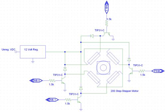
Figure 5: Motor driver interface circuit
The motor driver interface circuit is very similar to the fan driver interface circuit. A 12-volt voltage regulator provides the power to run the stepper motor (it draws 200 mA of current, continuously). The TIP31-C is capable of providing the required current to the stator windings, and additionally, they isolate the MCU from back EMF. It should be noted that at all times the light is on, this circuit draws power, which it uses to lock the axle in place when the color wheel is not spinning. The motor spins by receiving signals from the MCU. For example, in order to make the motor spin clockwise as seen in the schematic above, the ports would have to be successively pulsed in a periodic sequence: turn on PINB.3 for 5 msec then turn it off, turn on PINB.2 for 5 msec then turn it off, turn on PINB.1 for 5 sec then turn it off, turn on PINB.0 for 5 msec, then turn it off, turn on PINB.3 for 5 msec then turn it off…. Every time a period is cycled (from PINB.3 to PINB.0) the motor turns 1/5 of the distance to the next color. Hence, five periods are required to rotate the stepper motor to the next color from the previous color. The same sequence, but in reverse order, is used to spin the motor counter-clockwise.
software Design
Programmed in CodeVisionAVR C, our software interfaces the MCU with the stepper motor, muffin fan, and audio signal to produce a club light that randomly outputs a new color at the detection of a bass beat off an input music signal. We use the ATMEL 90S8515 at a clock speed of 8 MHz. By using timer 0, we set the reload value so we would have an interrupt trigger every 1 msec, thus creating our time base for our main tasks in our code.
Test File
Originally, we wrote a simple C file (steptest80.c) to test the operation of our stepper motor to accurately test the movement of the color wheel. We determined that we needed to pulse the 4 pins of the motor 5 times (or 20 steps) to take the color wheel from one color to the next color. By pushing push buttons 0, you will make the color wheel turn 20 steps in the counter-clockwise direction, while pushing push button 1, will make the color wheel turn 20 step in the clockwise direction. Push button 2 would make the wheel turn counter clockwise enough steps to reset the position of the color wheel to position 0 or black.
Final File
Our final C file (final.c) has one task and multiple functions called from those tasks.
Task1()
Task 1 would test pin 7 of port D, which signaled whether the temperature was higher or lower than the set point temperature of 90°F. If the temperature read exceeded 90°F the muffin fan would turn on and once the temperature would fall below this set point, the muffin fan would turn off. From the temperature sensor circuit in Figure 3, the fan will turn on when the voltage on pin 7 equals 0V and will turn on when pin 7 equals 5V.
cw()
This function would turn the stepper motor in the clockwise direction according to how many offset positions the next color is. The variable color is then updated so it knows what color it just moved to.
ccw()
This function would turn the stepper motor in the counter-clockwise direction according to how many offset positions the next color is. The variable color is then updated so it knows what color it just moved to.
beat()
When beat is called, it grabs the value of the counter to obtain a random number and then takes this number modulo 11 to get a number from 0 to 10.
|
Color Codes |
|
|
0 |
Black |
|
1 |
White |
|
2 |
Light Green |
|
3 |
Blue |
|
4 |
Yellow |
|
5 |
|
|
6 |
Green |
|
7 |
Amber |
|
8 |
Pink |
|
9 |
Magenta |
|
10 |
Strobe |
First, the program checks to see if color code 10 was selected. It then goes through a sequence of 5 strobes to generate a strobe light effect. It first detects whether white (color=1) requires a counter-clockwise or clockwise rotation. After the color wheel moves to white, a series (5 times to be exact) of counter-clockwise or clockwise rotations are made to produce a strobing effect of the color wheel. After this strobe is performed, it breaks out of beat() and waits until the next beat is detected.
If the color code is anything different than 10, by using the new color code versus the current color, we are able to determine which direction the color wheel should be rotated and by how many positions. More specifically, next color is subtracted from the current color to obtain the number of positions the color wheel needs to rotate. If this number is negative a clockwise rotation of the color wheel is required to move to the next color. If this number is positive a counter-clockwise rotation is required.
RESULTS
Our CLUB Light works
very nicely. It detects the beat off of
a line-level voltage (through an RCA cable).
The user is given the option of setting the final gain for detecting the
beat using a hard-wired potentiometer. The
light appears to have no glitches, and the stepper
motor changes the colors randomly and smoothly.
The light is greatly improved over the original, factory light. It runs at a cooler temperature, uses less
power, and utilizes all of the colors in a much more random fashion. You may watch a short clip using QuickTime
here:
Next Time
1. Add User Controls
If we had more time, we would have like to add more user control functionality. For instance, the user would be able to select which colors (out of the 9 colors) they want to use as well as program the sequence they will flash in. We were thinking that we could interface the keypad with the MCU so the user could set these features as desired. Better yet, we could add DMX controls!
DMX is a lighting industry standard way of controlling lighting equipment. It allows for one controller to control many lights. DMX is used for controlling mainly the brightness of lights, and can be used for controlling moving lights, smoke machines, strobe lights and so on. It basically consists of one 8-bit (on or off) signal for each light which sets the brightness level of the light to one of 256 levels.
Electrically, DMX is a bus where there is one transmitter and multiple receivers. DMX wiring uses 5-pin XLR connectors with 120 ohm shielded twisted pair wiring. The protocol used in DMX-512 bus is similar to normal serial communications (like RS-232 with 8 data bits + 1 stop bit) and operates at 250 kbps (arguably difficult using a microprocessor, but it can be done!).
2. Improve Color Wheel Speed
It would be nice if the stepper motor allowed us to change the colors more
quickly. We tried increasing the voltage
to the motor, but this does not appear to make the motor spin more
quickly. Additionally, reducing the
delay after each pulse is applied only causes the motor to vibrate in position
for values less than 5 milliseconds.
Perhaps one could make the stepper motor rotate faster by starting the
rotation using all four of the control lines, then once momentum was
established, one could reduce the rotation time by using only every other
control line.
PICTURES
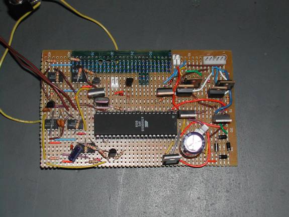
The protoboard that was built to house the MCU and its analog
interfacing circuits. The stepper
motor attaches on the six pin connector at top right, along with the analog
interfacing. The fan plugs in using the
two-pin connector just to the left of the stepper motor connector. Finally, the lamp control plugs in at the
middle-top portion of the board. 12 VAC
is supplied just above the large capacitor in the lower right corner. The temperature sensing circuitry is in the
top-left hand corner, and the audio signal is processed in the bottom-left
corner.
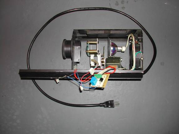
The overall gutted light. Note that the large blue cube in the center
of the image is the relay used to turn on the light. 120 VAC is supplied to the board via the
green connector. The 120 VAC to 12 VAC transformer is just below lamp, and the stepper motor is
just above the blue relay. The muffin
fan is on the right side of the unit.
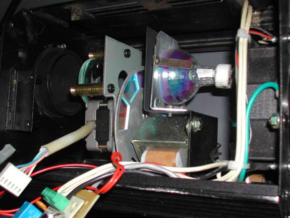
A close up of the transformer, lamp,
stepper motor. Note the color wheel
between the lamp and the stepper motor.
Links
History of Disco
Lighting:
http://www.njd.co.uk/hodl.html
Vortex:
http://www.americandj.com/product.asp?ProductIDNumber=789&cat=Lighting_DISCONTINUED – Product Page
http://www.americandj.com/pdffiles/VORTEXG.pdf -- Vortex User Manual
Stepper Motors:
http://www.doc.ic.ac.uk/~ih/doc/stepper/index.html
-- overview
http://www.cs.uiowa.edu/~jones/step -- a tutorial on control
Where to Buy Club
Light:
http://www.americandj.com -- the main retailer of Club Lights
http://www.mbtlighting.com/ : -- Higher-end Club Lights
DMX Info:
http://www.epanorama.net/links/lights.html#control – DMX broad overview
http://www.pangolin.com/LD2000/dmx-about.htm -- DMX pinout and cabling details
http://www.rosco-et.com/dmxtour.htm -- DMX tour
http://www.dmx512.com/web/light/dmx512/index.htm -- DMX technical info
http://ftp.unina.it/pub/electronics/ftp.armory.com/DMX/ -- DMX technical documents
Light Chaser
Circuits:
http://members.fortunecity.com/techman10/lights/audio_tr.html
APPENDIX – A (OUR
CODE):
PROGRAM LISTING
Steptest80.c – test code for stepper motor
Final.c – code for controlling club light
STEPTEST80.C
//ECE476
– Alex Cerruti and Chris Wherry
//STEPTEST80.c
– tests operation of stepper motor
//rotates
wheel counter-clockwise, clockwise, and reset
//
with different buttons pushed.
#include
<90S8515.h>
#include
<delay.h>
//timeout
values for each task
#define
t1 25
#define
t2 25
unsigned char reload; //timer
0 reload to set 1 mSec
unsigned char time1; //timeout counters
unsigned char count; //light
states
//the
three task subroutines
void
task1(void);
void
initialize(void); //all the usual mcu stuff
//**********************************************************
//timer
0 overflow ISR
interrupt [TIM0_OVF] void timer0_overflow(void)
{
//reload to force 1 mSec
overflow
TCNT0=reload;
//Decrement the three times if they are not
already zero
if (time1>0) --time1;
}
//**********************************************************
//Entry
point and task scheduler loop
void
main(void)
{
initialize();
//main task scheduler loop
while(1)
{
if (time1==0) task1();
if (time2==0) task2();
}
}
//**********************************************************
//Task
subroutines
//Task
1
void
task1(void)
{
time1=t1; //reset the task timer
if(PINB.0==0)
{
//make motor step forward twenty steps
for(count=0;
count<5; count++)
{
PORTA = 0x01;
delay_ms(5);
PORTA = 0x02;
delay_ms(5);
PORTA = 0x04;
delay_ms(5);
PORTA = 0x08;
delay_ms(5);
}
}
else if(PINB.1==0)
{
//make motor step backward twenty steps
for(count=0;
count<5; count++)
{
PORTA = 0x08;
delay_ms(5);
PORTA = 0x04;
delay_ms(5);
PORTA = 0x02;
delay_ms(5);
PORTA = 0x01;
delay_ms(5);
}
}
else if(PINB.2 == 0)
{
//make motor to reset position
for(count=0;
count<52; count++)
{
PORTA = 0x01;
delay_ms(5);
PORTA = 0x02;
delay_ms(5);
PORTA = 0x04;
delay_ms(5);
PORTA = 0x08;
delay_ms(5);
}
}
else
{
PORTA = 0x08; //otherwise
lock the colorwheel in place
}
}
//**********************************************************
//Set
it all up
void
initialize(void)
{
//set
up the ports
DDRB=0x00; //PORT
D in an input
DDRA=0xff;
// PORT A is an ouput
PORTA=0x00;
//PORT C is an output
DDRC =0xff;
PORTC = 0x00;
reload=256-250;
//value for 2 Msec for 8 MHz
TCNT0=reload;
TIMSK=2;
//turn on timer 0 overflow ISR (Mega pg. 30)
TCCR0=3; //prescalar to 64
//init the task timers
time1=t1;
//make motor to reset position
for(count=0;
count<52; count++)
{
PORTA = 0x01;
delay_ms(5);
PORTA = 0x02;
delay_ms(5);
PORTA = 0x04;
delay_ms(5);
PORTA = 0x08;
delay_ms(5);
}
//crank up the ISRs
#asm
sei
#endasm
}
FINAL.C
//
Final Project – Disco Light
//
Alex Cerruti and Chris Wherry
#include
<90s8515.h>
#include
<delay.h>
//timeout
values for each task
#define
t1 25
#define
t2 50
unsigned char reload; //timer 0 reload to set 2 mSec
unsigned char time1, delay; //timeout counters, delay produces a crude debounce
unsigned char beat_flag;
//light states
int count, color, next_color, positions;
//define variables for functions
//the
three task subroutines
void
task1(void); // turns fan on and off
void
cw(void); //
function to move color wheel one color clockwise
void
ccw(void); // function to move color wheel one color
counter-clockwise
void
beat(void); // control movement of color wheel with inputted music
void
initialize(void); //all the usual mcu stuff
//**********************************************************
//timer
0 overflow ISR
interrupt [TIM0_OVF] void timer0_overflow(void)
{
//reload to force 1 mSec
overflow
TCNT0=reload;
//Decrement the three times if they are not
already zero
if (time1>0) --time1;
}
//**********************************************************
//Entry
point and task scheduler loop
void
main(void)
{
initialize();
//main task scheduler loop
while(1)
{
if
(time1==0) task1();
if (PIND.6==0
& beat_flag==0) // we detect a beat
{ // set flag so we only change one
color per beat
beat_flag=1;
// we have reached a beat call beat() function
beat(); //
call beat and change color
delay=t2;
}
if (PIND.6==1
& --delay==0)
{
delay = t2;
beat_flag=0; // no
more bass beat ready for a new beat
}
}
}
//**********************************************************
//Temperature
turn on fan function
void
task1(void)
{
time1 = t1;
if(PIND.7 ==
1) //turn off the fan in this
case
{
PORTC = 0xf0; // keep halogen on, but turn off fan
}
else //otherwise turn it on
PORTC = 0xff;
}
//**********************************************************
// Function
that moves it counter-clockwise
void
ccw(void)
{
//make motor step forward twenty steps
for(count=0;
count<5*positions; count++)
{
PORTB = 0x01;
delay_ms(5);
PORTB = 0x02;
delay_ms(5);
PORTB = 0x04;
delay_ms(5);
PORTB = 0x08;
delay_ms(5);
}
}
//**********************************************************
//
Function that moves it clockwise
void
cw(void)
{
//make motor step backward twenty steps
for(count=0;
count<5*positions; count++)
{
PORTB
= 0x08;
delay_ms(5);
PORTB = 0x04;
delay_ms(5);
PORTB = 0x02;
delay_ms(5);
PORTB = 0x01;
delay_ms(5);
}
}
///////////////////////////////
//
Color Table:
// 0
– black
// 1
– white
// 2
– light green
// 3
– blue
// 4
– yellow
// 5
– orange
// 6
– green
// 7
– amber
// 8
– pink
// 9
– magenta
//
10 – strobe
////////////////////////////////
void
beat(void)
{
next_color = TCNT0
% 11; // get a random number
between 0 and 10
if (next_color == 10)
// if strobe
{
next_color=1; // first set to white
// move to white from current color
if (next_color-color>0)
{
positions =
next_color-color;
// calculate number of positions needed to turn
ccw();
color = next_color;
// keep track of new color
}
if (next_color-color<0)
{
positions =
color-next_color;
// make sure positions is positive
cw();
color = next_color;
// keep track of new color
}
// now oscillate between black and white
for 5 times
positions=1;
for(count=0;
count<5; count++)
{
cw(); // now on black
ccw(); // now on white
}
}
else if (next_color-color>0)
{
positions = next_color-color; //
calculate number of positions needed to turn
ccw();
color = next_color;
// keep track of new color
}
else if (next_color-color<0)
{
positions =
color-next_color;
// make sure positions is positive
cw();
color = next_color;
// keep track of new color
}
}
//**********************************************************
//Set
it all up
void
initialize(void)
{
//set
up the ports
DDRD=0x00; //PORT
D in an input
DDRB=0xff;
//PORT B is an output
DDRC =0xff;
//PORT C is an output
PORTB=0x00;
//initialize PortB to 0
PORTC=0xf0;
//nitialize PortC to
f0 (turn on light/fan off)
//
For 8515:
// UCR = 0x10 + 0x08 ;
// UBRR = 51 ; //using
a 8 MHz crystal
reload=256-125; //value for 1 msec
for 8 MHz
TCNT0=reload;
TIMSK=2; //turn
on timer 0 overflow ISR (Mega pg. 30)
TCCR0=3; //prescalar to 64
//init the task timers
time1=t1;
//make motor to reset position
// color will then be black
for(count=0;
count<52; count++)
{
PORTB = 0x08;
delay_ms(5);
PORTB = 0x04;
delay_ms(5);
PORTB = 0x02;
delay_ms(5);
PORTB = 0x01;
delay_ms(5);
}
beat_flag = 0; // nitialize beat flag to zero (received no base beats yet)
color = 0; // black
next_color = 0; // nitialize
positions = 0; //
how many positions to turn
delay = t2;
//crank up the ISRs
#asm
sei
#endasm
}
APPENDIX B – (OUR
SCHEMATICS):
SCHEMATICS

Figure 1:
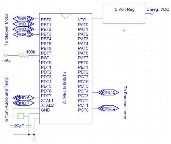
Figure 2: The Atmel 90S8515 Microcontroller Unit and its associated ports
Figure
3: The Temperature Sensor (top half) and
Beat Detector (bottom half)
Figure 4: Fan and lamp driver interface circuits
Figure 5: Motor driver interface circuit