(not a newspaper, and not witty)
ECE 476 Final Project , Spring 2002
Tyson Bergland & Derrin Berger
Take a look at the "finished" product. Click here.
For years scientists and scholars alike have been plagued by one common obstacle which, until now, has proven to be impossible to overcome. How do you find the country you want on a globe? Sure, the easy answer is to just use the longitude and latitude coordinates, but really, that's quite confusing. Some may even say to just do a web search to take a look at the country, but this really doesn't have the convenience we're looking for, and could potentially take hours or even days to finally get an answer. This is why we've developed a globe that will spin and point to 1 out of a possible 11 countries you wish to see. This may not appeal to some, but we feel that for a generally useless gadget that can possibly make a difference in about a dozen peoples' lives, nothing can beat "The Rotating Globe".
The general concept is simple. We asked a friend to name the first gadget that came to mind and he said, "I want a globe that will spin to any country I want". So, we delivered. Using an Atmel microcontroller, and few motors, and a lot of scotch tape, we make one of the greatest contributions to educational technology ever invented by make a globe that will, indeed, spin to any country you want. The result is a system that is both educational and mildly amusing.
The user can either
enter a country's ID number or a longitude and latitude value into the keypad
and the globe rotates to the desired country.
The country's name, longitude, and latitude are then displayed on the LCD
screen. One motor rotates the globe
to the correct longitude and the other motor moves a pointer to the correct
latitude. The microcontroller
stores the present location of the globe and steps the motors the shortest
distance possible.
We decided to sacrifice
motor strength for stepping accuracy. Consequently,
a pointer is used to indicate latitude instead of spinning the globe because the
stepper motor is not strong enough to spin both the mass of the globe and the
other stepper motor. The axis of
the globe was placed at perpendicular angle to minimize the amount of mass the
motor needed to move. A slow
stepping speed was also used to ensure that the momentum of the spinning globe
does not cause a skipped step.
Summary of Operation
After powering on, the first operation is to calibrate the machine. By pressing '0' followed by a '#', the machine enters a calibrate mode which allows the user to give the globe an accurate starting place. Generally, the pointer will move up to the equator, and the user can manually turn the globe so that the pointer is on the Prime Meridian.
Once the machine is calibrated, the user had two options: either enter a country code, or a specific latitude or longitude. If a country is desired, the number entered must be one of the codes already programmed, followed by a '#'. Numbers entered that are followed by a 'A', 'B', 'D', or '*' will cause the globe to spin and/or point to the corresponding latitude or longitude entered. We assume the user will only enter valid coordinates.
Summary of Buttons
| # | Go to specified country |
| A | Go to entered East Longitude |
| B | Go to entered North Latitude |
| C | Clear LCD screen |
| D | Go to entered W Longitude |
| * | Go to entered South Latitude |
Current list of locations
| 0 | Calibrate Mode |
| 1 | Germany |
| 2 | Russia |
| 3 | Turkey |
| 4 | England |
| 5 | Mexico |
| 6 | Japan |
| 7 | China |
| 8 | Australia |
| 9 | Norway |
| 10 | Argentina |
| 11 | Bolivia |
| 12 | USA |
The software design is
not overly complicated. There are
three basic state machines. One
machine is the standard debouncing state machine that we have used most of the
semester. When a proper country ID number is entered and followed by
the '#' button on the keypad, the rotation state machine is started and the
country's name, longitude, and latitude values are displayed on the LCD screen.
The other feature is to enter in a longitude and latitude manually.
This action changes the destination location as well , which triggers the
rotation state machine.
The rotation state
machine first translates the longitude and latitude values that are stored in
memory to motor ticks (400 ticks for a full rotation).
Then the destination coordinates are compared to the present location
coordinates. The difference between
the coordinates is placed in the amount to rotate in each direction. The globe can rotate in either direction, so the program
ensures that the motors rotate the shorter distance by comparing the absolute
values of the amount to rotate. Every
60 milliseconds, the program checks the amount to rotate in both directions.
If it is negative, it rotates backwards and increments the amount to
rotate. If it is positive, it
rotates forwards and decrements the amount to rotate.
The rotation of the globe and the movement of the pointer alternate one
tick at time. If the amount to
rotate is zero, nothing happens.
Stepping a motor
forwards and backwards also requires a small state machine.
Basically, if the input to the motor was 9, set it to 5, then 5 to 6, 6
to 10, and finally 10 back to 9, and on each state transition, the motor ticks
forwards once. Transitioning
through the same states in the reverse direction will have the motor tick in the
other direction. The values that the state machine drives to the port are
pulses that allow the H-bridge circuit to drive the motor.
Materials Used
Atmel Mega163
STK 200 evaluation board
(2) L293D H-bridge driver IC's
(2) 10k resistors
9" globe
protoboards, power supplies, some tubing, and a ton of tape
The globe is controlled by the Mega163, which is programmed and run on an STK evaluation board. The microcontroller provides the pulse sequences needed to drive the motors, interprets the keypad, drives the LCD display, and provides the 5v VCC and GND used by the H-bridge driver circuit IC's.
KeyPad and LCD Setup
A 16 button keypad was used to accept user input. It resembles a grid that connects corresponding rows and columns to single out the button that was pressed. The schematic for its connection to PORTD of the microcontroller is shown in Figure: 2.
The LCD screen is a 16 characters per line, 2-line display. It uses a potentiometer to control its contrast and is driven by PORTC of the microcontroller. The schematic is shown in Figure: 3.
Driving the Motors
Since the stepper motors are bipolar, there are no center taps on the inductor coils, which means that current needs to be driven in both directions through each coil on the motor. The simplest way to do this is with an H-Bridge driver circuit which, in its basic form, is 4 transistors which are tied together so that when the proper pairs are turned on, current flows through the center in one direction, and in the opposite direction when the other pair is turned on. Rather than build this circuit ourselves, we used an L293D for each motor. The L293D contains 2 H-Bridge driver circuits with enables and protection diodes, and can take up to a VCC2 of up to 36V, which is used to drive the motors. The pulse sequences were driven with pins 0-3 of PORTA and PORTB of the microcontroller, which feed into the h-bridge circuit that drives the motors. It was found that when both motors are run at high voltages, they tend to become unstable and jittery, most likely due to crosstalk between the wires driving the motors with high speed pulses. They actually perform better at lower voltage levels, so we usually run them at around 3V, which is a little higher than the turn on voltage (which appears to be ~2.25-2.5v) and gives the motors a little bit more strength and stability. The schematic for this setup is shown in Figure: 4.
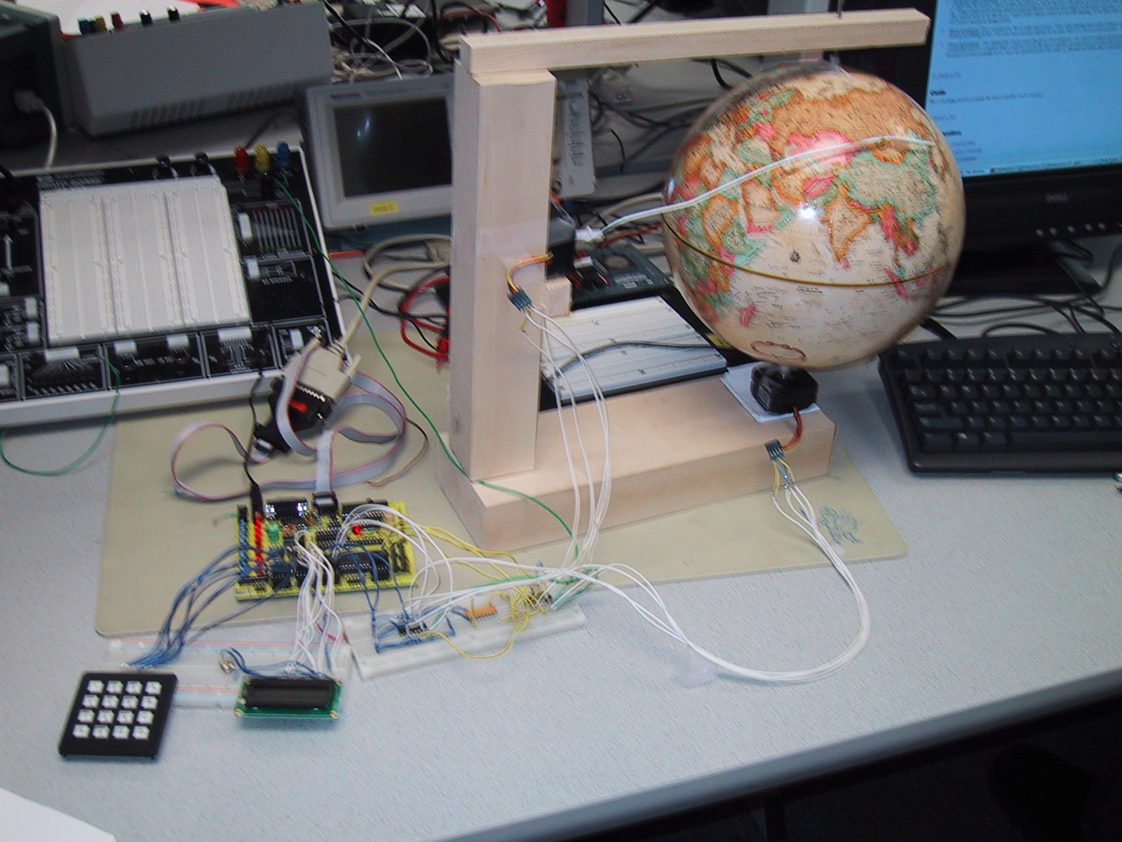
The Globe Stand and MechE annoyances
Although this proved to be one of the more difficult components to construct (because MEng ECE people are incapable of using a hammer), the globe stand is simple in its design. The stand is constructed of balsa wood which provides a few good benefits. First, it makes the whole assembly very light. Second, the wood is so soft that in the absence of a hammer, a nail can simply be pushed through the wood with your thumb. The motors are attached to the stand with scotch tape, because it was there. Also, it helps when trying to line things up properly if there isn't glue on the motor.
Getting something to attach to the motors properly is a nightmare, since we sacrificed accuracy for ease of use. The shafts of the motors are about a half inch long, and are not threaded. So, without a welding torch, getting anything to stick to it is a nightmare. After trying pieces of cork, wooden toy wheels, and super glue, we finally settled on a small plastic hose that got wedged around the shafts. Apparently, the torque of the motors is not what we thought it was going to be, because the more secure we made things, the worse it worked. Taping the globe to small disk that was wedged to the motor didn't work, yet leaving it un-taped did. We don't remember much about mechanics or friction or things of this nature, so we just used a bunch of scotch tape and rammed the globe on top if it. The pointer for the globe was assembled the same way, a bent coat hangar and a bunch of tape. The reason we use a coat hangar is because the flexibility of the metal is just right to achieve the shape that we needed, and also because it was right there on the floor when put the stand together.
A diagram of this setup is show in Figure: 1.
Everything worked as expected and planned. The globe rotated and pointed to the capital city of every country we tested. Even after checking 15 or so countries in a row, there seemed to be no loss of accuracy that would require recalibration.
What Have we Learned?
There are only a relatively small number of improvements that could've been made to the design, especially since a rotating globe isn't high on anyone's priority list:
Accuracy and Precision: The current design is accurate to within 0.9 degrees because the stepper motors provide 400 steps per revolution. It is possible to half-step the motors, which doubles the precision, but for the size of the globe we used, and the time and financial budgets we were on, it really isn't worth it. Using a larger globe means that the physical distance between each degree on the globe is greater, so it having better accuracy is much more worthwhile. The easiest ways to do this are to: 1) get a better stepper motor and use half-stepping, 2) use drive belts to gear motor down, and 3) use a really, really slow DC motor and get its timing perfect.
More Locations: For our purposes, this is really unnecessary. First of all, entering all possible locations on the earth is a task worthy of a sophomore CS student, not MEng ECE's. Second, since memory will also be an issue, there's no reason to try to push it. So, add more memory, and add more locations.
Voice Activation: Our original plan was to make the globe voice activated. So, once a country is spoken into a microphone, a voice recognition chip would convert the word to a number which could be read by the microcontroller and matched to a location stored in memory. Under advisement against this because it could potentially be too hard, we abandoned the idea early on, although we believe this could easily be done, and at a relatively low cost as well.
The code listing used to program the microcontroller can be see here.
Figure 1: General setup of globe, stand, & motors


Figure 4: Motor Driver Circuits