|
|
|
|
There were several different ways to implement the following parts of the project: List of IC's and maufacturers of video overlay IC's, temperature, pressure sensors Microcontroller unitI decided to use the Atmel Mega163 because of my familiarity with the MCU. The Mega163 has a 8 port ADC and several multipurpose I/O ports, which were sufficient for my project. Video Overlay GenerationAs for the video overlay generation, there were two main options:
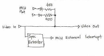
The following analysis of the video generation assumes some knowledge on NTSC video, for a primer please read http://www.efd.lth.se/~e96rg/mc/video/rtvideo.html. The MCU can drive a video signal with an addition of a sync extractor and a 2 bit digital to analog converter. The sync extractor is needed to ensure that the signals generated by the MCU are in sync with the video input to prevent the overlaid image from jittering.
Figure 1. A possible schematic for connecting the MCU directly to the video input. Generating the video overlay with the MCU might lower costs and complexity of the circuit. However a shortfall of this method is the low resolution of the video signal generated by the MCU. Each NTSC scanline is only 64us long with a 52us visible part. For a 8 Mhz MCU, that translates to about 416 possible instructions per visible part of each scanline. Assuming we can load the output data and write to the DAC in 2 instructions, that leaves us with a maximum of 208 pixels per line. This estimate does not take into account that we must convert the output text buffer into a bit mask, hence the effective horizontal resolution may be much less than 208 pixels. A decent character would have to be at least 8 pixels wide, resulting in less than 26 characters per line. We have not taken into account the processing power required for the sensors and user interface which might lead to a further reduction in the resolution. Therefore it is not feasible to generate the video overlay signal within the MCU itself. The best method is using a video overlay IC driven by the MCU. A major benefit of this approach is stable image generation. Image jitter is caused when the MCU cannot produce the signal exactly on time, possibly because it could be occupied with other processes. By handling the video generation with a dedicated IC, the video generation is no longer sensitive to delays in the MCU. SensorsThe specifications for this project required a pressure sensor, a temperature sensor and two ADC inputs. The ADC is already handled by the MCU, thus no extra components were required. As for the temperature sensor, there were several choices. I could have used an analog temperature sensor like the national semiconductor LM34, or a digital sensor. I choose to use a digital sensor because that would save me from having to insert an op-amp between the MCU and the sensor. Hence lowering the cost and simplifying the circuit. Also, the temperature sensor could be placed quite far from the main unit and hence digitizing the temperature before transmission would reduce noise in the measurements. As for the type of digital interface for the temperature sensor, there was a choice of either the Phillips I2C bus or the Dallas Semiconductor 1-wire bus. Since I could find no pressure sensor utilizing the I2C bus I decided to use the 1-wire bus. While searching for a pressure sensor, I learned that there are 3 major types:
I needed the absolute type for my project. Even then there were choices of the dynamic range for the pressure sensors. There were pressure sensors for measuring 10,50,100 or 200 kPa. The sensitivity of the sensor must match its application or else the sensor would either experience excess pressure and fail or be unable to detect pressure changes in the target application. Since standard pressure is about 100kPa, a sensor of that range would be suitable. User InterfaceGoing on to the user interface, I needed some way of letting the user enter the text to be overlaid. One way would be to connect the RS-232 of the MCU to a computer and let the user type from Hyperterm. However that would limit the use of the unit to places where a computer is available. I wanted the unit to be portable and so decided to let the user enter text via a PS/2 keyboard. PS/2 keyboard are cheap, inexpensive and common. Hence the PS/2 keyboard was perfect for my application.
|
|
|