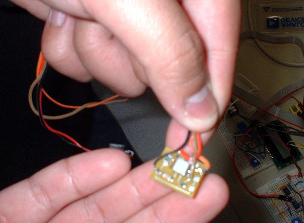
This picture shows the actual accelerometer used.
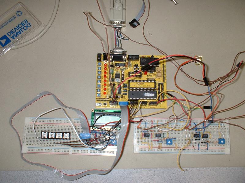
The following picture shows the entire circuit along with the STK200
development board. The special serial dongle was built to tap the RTS and DTR
signals.
The bread board on the right contains the circuit that boasts and formats the
output voltages into voltages the STK200 board can handle. The bread board on
the left contains the LCD displace and the push buttons.