Introduction
The
goal of this project was to build and implement an inverted pendulum
balancer, in the vertical two dimensional plane, using Proportional-Integral-Derivative
(PID) feedback control.
The
inverted pendulum balancer is a radio controlled car modified
by adding a plexiglass platform and an inverted pendulum with
free rotating pivot. The electrical component of the balancer
brings together computational hardware (Atmel Mega32 microcontroller),
an input angle sensor (US Digital Optical Shaft Encoder), and
an output motor driver (National Semiconductor LMD18200 H-Bridge)
onto a single board whose sole purpose is to autonomously control
the motion of the car in order to keep the pendulum from falling.
Motivated
by the School of Mechanical & Aerospace Engineering’s
Feedback Control Systems course at Cornell University, our desire
was to integrate the knowledge of stabilizing an unstable system
using feedback control (MAE478), the fast, flexible computing
power of microcontrollers (ECE476), and the use of real-world
engineering tools and budgetary constraints imposed on us by project
managers. The result was a simple, cheap, and fun device that
completed our desired goal.
High
Level Design
Our
motivation originated from Feedback Control Systems (MAE478),
a course that we are both currently enrolled in. We wanted to
attempt at a project where we could implement a feedback controller
with a microcontroller. The question was what to control. After
doing some research, we found a Stanford University EE281 project
by Geoffrey Bainbridge. This "Self-Balancing Robot"
project attempted to design a one-legged robot which balances
itself using a feedback control with Atmel Mega163 microcontroller.
Bainbridge attempted to balance a rod directly connected by two
wheels. He quickly added a third supporting wheel and pivot after
the two wheel design created unwanted rotational motion about
the vertical axis. In addition, Bainbridge used a tilt sensor
to measure the robot’s angle. However, the tilt sensor proved
to be inaccurate due to the combination of the robot’s horizontal
acceleration and the arm’s gravitational freefall.
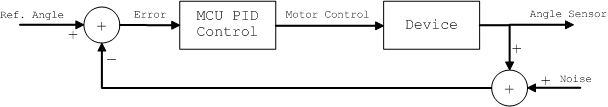
The
basic structure of the feedback control system is shown below.
The angle sensor reading is subtracted from the reference angle
to produce the error. This error is used to calculate the motor
control parameters using the PID algorithm (discussed below).
The motor control is then sent to the device. We decided to keep
our feedback control system SISO (single-input single-output)
instead of MIMO (multi-input multi-output) for simplicity to help
with our black-box modeling. The reference angle is the only input
to the system, and the feedback control uses the error in angle
from the reference and calculates a motor output.
Our
limited mechanical engineering ability, along with the short timeframe
to complete the project, favored the use of a prefabricated car.
A four-wheeled vehicle would not experience the rotational motion
that Bainbridge encountered in his project. RadioShack’s
extensive selection of toy Radio Controlled cars made our selection
process very easy. Once a stable vehicle with fast response characteristics
was discovered and modified to hold an inverted pendulum, the
search turned to finding a reliable, high-resolution angle sensing
device. The two most viable choices were a MEMS accelerometer
or optical encoder. After initial testing, the analog accelerometer
could not perform as well as the digital encoder. Therefore, the
1024 cycles per revolution (CPR) optical shaft encoder from US
Digital became our angle sensor. This is a vast improvement over
the tilt sensor, as the encoder was not affected by the effects
of gravity or the car’s acceleration.
The
Atmel Mega32 microcontroller was used instead of the Mega163 due
to its superior speed, for external interrupt sampling of the
encoder data, and more versatile timer options. Initial black-box
testing of the car’s DC motor capabilities gave us a good
idea of the car’s performance. Different driving scenarios
were observed, including single-direction driving and oscillatory
motion. Upon finishing motor control, we moved on to testing the
sensor. The optical encoder’s input signals were quickly
converted to an error angle referenced from its initial count
value.
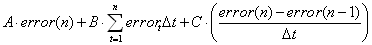
The
final design stage was the Proportional-Integral-Derivative (PID)
Controller to relate angle error to motor velocity and direction
(see equation below). The proportional term (A) applied a voltage
to the motor proportional to the error. This value affected the
cart’s response time; higher the proportional term, the
faster the car’s response at the expense of system stability.
The integral term (B) would correct any steady-state error that
would occur due to any sluggish response by the motor. Integral
control would give the motor a little extra “push”
to ensure correct tracking of the reference angle. However, a
higher integral control term would create oscillations that are
either unrecoverable or may throw the system to instability. Finally,
the derivative term (C) is used to smooth out changes in error
over time. This term can usually smooth out the oscillations in
the vehicle at the expense of slower response. Fine-tuning of
these three variables according to system behavior will allow
the car to balance the inverted pendulum.
Program
& Hardware Design
Hardware
Deisgn - The hardware required for the inverted pendulum
balancer can easily be separated into 2 subsystems: Mechanical
and Electrical.
Mechanical:
Our first priority was to quickly acquire a device capable of
forward and reverse motion, with quick transitions and fast acceleration.
Lacking the knowledge of mechanical cart design and the ability
to gear a motor correctly for sufficient torque to move the cart,
we quickly adopted the idea of using a radio controlled car as
our base. After testing various RC cars from RadioShack, we found
a car
that seemed to have the performance we required, along with a
sturdy base which would easily allow for a pendulum apparatus
to be installed.
The
vehicle’s DC motor was located in an easily accessible location
at the rear underside of the car. Six AA batteries were the manufacturer’s
defined power source; therefore, we knew our power supply would
have to supply at least 9 volts. The six AA’s were installed
with a break in the last contact of the battery holder and an
ammeter (DVM set to measure current) in series to measure the
current drawn by the device. With the car not under load (i.e.
not on the floor with the wheels in the air), the device drew
300 mA. We estimated that under load, the car would require at
least 600-800 mA to run with enough power. After rummaging through
many power supplies in the Phillips Hall Digital Lab, we found
a 12v 1500mA power supply from RadioShack, which would be more
than enough for our needs. It was later discovered that under
load and quick transition in motion, the device actually drew
approximately 900mA from the supply.
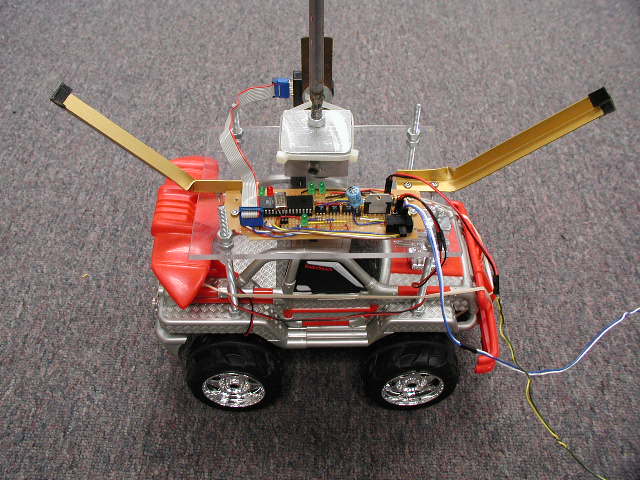
Upon
choosing our device, our next task was to build an inverted pendulum
on the car. A Plexiglas plate was used to create a platform on
which to attach the pendulum (see Image
9 ). This plate was secured to the car with 4 bolts at each
corner of the vehicle. At the center of the platform, two brackets
were placed with their inside angles touching each other, connected
by a ¼” screw, and used to create the pivot of the
pendulum (see Figure
3). Finally, a 38” rod (3/8” diameter) was screwed
into the center of the top bracket to create our pendulum. It
would seem strange to have a 38” rod above a 12” car.
The rod’s height, by design, however, acts in our favor,
as the larger moment of inertia (and higher center of mass) actually
slow down the rod’s initial movement. The added weight to
the vehicle would amplify the unwanted effects of the car’s
suspension system. Therefore, four elastic bands were placed around
the car in order to lock the shocks in a compressed position.
With
the pendulum sitting on the top bracket, and the screw acting
as a pivot, our next task was to be able to detect the angle and
direction of the pendulum’s tilt. Our first option was a
MEMS accelerometer from Analog Devices, ADXL202E. However, initial
tests proved that the accelerometer’s analog signal would
not provide us with the resolution that we required for angle
detection. The digital output of the leadless, surface mount ADXL202E
was disabled with the PCB that we used to mount it. Therefore,
we turned to the MAE department, where we were able to borrow
a 1024CPR (cycles per revolution) optical shaft encoder
from MAE478’s feedback lab.
Rather
than using the encoder’s shaft as the pivot, we decided
to use an approach that would put the least amount of stress on
the delicate piece of equipment. The encoder was placed in parallel
with the pendulum’s bracket. The height of the encoder’s
shaft was aligned with the pivot, effectively creating an imaginary
line from the pivot to the encoder’s shaft. Finally, a pin
was attached to the shaft of the encoder, with plastic tie-wraps,
and connected to the pendulum’s bracket. The bracket had
a 0.096” hole drilled above the pivot such that the pin
would fit tightly, without slipping; therefore, when the pendulum
moved, the encoder’s shaft rotated (See Figure
3, Image
3 and Image
4).
Electrical:
Once
the unstable pendulum was assembled and mounted on the car, an
electrical circuit had to be designed to accept information from
the optical encoder, process the information, and then control
the vehicle in forward and reverse motion. We did not need any
radio control circuitry or turning capabilities for our design;
therefore, the car’s motor lines were separated from the
rest of the manufacturer’s circuitry by clipping the wires
leading to the motor. Applying a potential to the motor leads
will cause the motor to spin in one direction, while reversing
the polarity on the leads will cause the DC motor to pin in the
opposite direction. To control the car’s forward and reverse
motion, we required a simple 4-switch device (See Figure
1) that would ensure protection against a short of the DC
supply, that is, switches 1 and 4 or 2 and 3 could never be closed
at the same time. To operate the motor in one direction, simply
close switches 1 and 3; for reverse operation, open switches 1
and 3 and close switches 2 and 4. To stop the motor completely,
simply open all switches.
Rather
than physically implementing each switch as a transistor, the
National Semiconductor LMD18200T H-Bridge was used. This convenient,
11-pin package accepts up to 55V supply voltage and can deliver
up to 3A of output current. The device contains the 4-switch setup
required for our motor control, along with protection diodes and
circuitry to ensure there is never a short from the supply to
ground. Upon connecting the supply (pin 6) and ground (pin 7),
only 3 inputs control the operation of the motor. A break bit
(pin 4) is used to effectively short the output terminals connected
to the motor. Without a potential difference across the motor
leads, the device does not operate. A high break bit implements
this feature; a low break bit will allow current to flow through
the motor. The direction of the motor is determined by the direction
bit (pin 3). When direction is high, output 1 (pin 2) will source
while output 2 (pin 10) will sink, and vice versa for a low direction
bit. Finally, the speed of the motor is determined by a pulse-width
modulated (PWM) signal at pin 5 of the H-Bridge. Speed is directly
proportional to the pulse width at this input; the higher the
duty cycle, the higher the speed of the motor. In addition, for
increased performance, 0.01 µF capacitors were placed from
each output to its corresponding bootstrap pin and a 100 µF
supply bypass capacitor (between motor supply and ground) to absorb
the recirculating currents of the inductive loads, as per manufacturer’s
recommendations. Without this 100 µF capacitor, the motor
behavior was very sluggish. The motor was connected to the H-Bridge
through a 2-pin header (See Figure
2, J3). Two more 2-pin headers were used for debugging purposes.
The first was placed in parallel to the 2-pin motor header(See
Figure 2, J2) such
that voltage across the motor could easily be measured. The second
header was placed in series between the H-bridge’s output
2 (pin 10) and the corresponding motor lead to measure current
going through the motor. Under normal operation, a jumper should
be placed across this header (See Figure
2, J1)
Once
the hardware to drive the motor was identified, we moved to creating
a stand-alone board such that all controls would be on the vehicle.
Using a 6” x 2-1/16” Perf Board, we began laying out
the necessary components for the Atmel Mega32 microcontroller
to run without the STK-500 development board. Our initial board
used a single 12V supply to provide power to both the MCU and
the motor. A Texas Instrument UA7805CKCS voltage regulator was
used to bring a regulated 5V to the MCU. A 0.1 µF capacitor
to ground was placed on each side of the regulator to block any
noise on the line from resetting the MCU. A 16 MHz crystal was
placed across XTAL1 (pin 13) and XTAL2 (pin 12), with a 27 pF
capacitor to ground at each pin. Finally, a 2x3 header was used
to allow for In-System Programming of the Mega32 (See Figure
2). The Vcc line in the ISP header was disabled. Connecting
the ISP’s 5V line, which brings in Vcc from the STK-500
during programming, to the MCU’s regulated Vcc line, which
comes directly from the 12V power supply, could lead to the two
supplies fighting each other if they were both on at the same
time. Therefore, we decided that the best option would be to disable
the ISP’s Vcc line, and always use our 12V supply line.
This, however, required the board to be powered externally when
programming. The MISO (ISP pin 1), SCK (ISP pin 3), MOSI (ISP
pin 4), ~Reset (ISP pin 5), and Ground (ISP pin 6) lines were
connected to the MCU’s pins 7, 8, 6, 9, and 11 respectively
to complete the In-System Programming setup. Finally, we dedicated
PORTD.4, D.5, and D.6 on the MCU as the 3 motor control signals;
Break, PWM, and Direction respectively.
Adding
the optical encoder to the circuit was the final step in the hardware
required to balance the pendulum. Output channels A and B from
the encoder (pins 3 and 5 respectively) were used to trigger external
interrupts on PORTD.2, D.3 respectively. The encoder was connected
to the circuit using a 1x5-pin header, which delivered +5V, ground,
and Channels A and B lines from the MCU to the encoder. (See Figure
2, J4) Turning on the power seemed the only thing stopping
our circuitry at this point.
Once
our software was ready to be tested, problems with the hardware
surfaced almost immediately; the most drastic being noise issues
orignating from the motor. Since only one power supply was used
(12V to the motor and regulated to 5V for the MCU), noise created
when the motor would change directions would travel down the ground
line and reset the MCU, which had an absolute maximum rating of
200mA DC current on Vcc and ground pins. Physically separating
the ground lines (but all leading to the same supply ground) did
not help. This was further seen when tested using the STK-500
and a separate H-Bridge on a prototype bread-board circuit. Since
noise kept resetting the MCU and the only line connecting the
STK-500 to the H-bridge was ground, an isolated ground scheme
had to be used. Therefore, we went from a single supply design
to two supplies, 5V to power the MCU and the encoder, and 12V
strictly to power the motor.
To
completely isolate the motor circuitry, which only consists of
the H-Bridge, from the MCU, three 4N35 opto-isolators are used
to detach the three MCU lines (break, PWM, and direction) from
their H-Bridge counterparts. This device uses an infared diode
to turn a phototransistor on and off. When current passes through
the diode, the transistor is essentially a closed switch, shorting
to ground in our application. When the photodiode is off, the
transistor is an open circuit and the output is high, 12V though
a 1 kOhm pull-up resistor. Since the 12V power supply is not regulated
and usually outputs around 14V, two LED’s in series were
placed between the 12V supply and the pull-up line to bring the
voltage to approximately 11V. This was done because of the H-Bridge’s
absolute maximum input rating of 12V on pins 3,4, and 5. The opto-isolator
is an inverting device, therefore, rather than inputting a signal
referenced to ground, we used 5V as the input and referenced it
to each of the three signals. Once the signals are inverted through
the opto-isolator’s transistor, the correct signals are
passed to the H-bridge, with exception that a logical high is
12V rather than 5V. Since the opto-isolators use phototransistors
that receive IR signals, there is no physical connection between
the MCU's circuitry to the H-bridge. Therefore, no noise from
the motor can go to the MCU.
Adding
the three opto-isolators made board layout very tight. Therefore,
only one power switch is used. The switch controls MCU power,
while 12V motor power is always connected. It is worthy to note
that if no input signals come in to the H-Bridge, the motors do
not run. Both power supplies are connected to the board with two-pin
headers. The complete separation of grounds between the motor
and MCU solved all noise issues, and allowed for high-speed motor
transitions without MCU reset.
Program
Design - There are three main functions in the final
controller code: sensor (encoder) input, PID control calculation,
and motor control output. The motor controller code (test_motor.c)
was written first. The DC motor is controlled via a H-Bridge and
three signals control the break (on/off), speed, and direction
of the motor. These signals were outputted from the pins on Port
D of the microcontroller to pins on the H-bridge. The speed of
the motor is controlled by a pulse-width-modulated (PWM) signal.
The current delivered to the motor is proportional to the pulse-width,
thus the percentage of duty-cycle period determines the speed
of the motor. Since we did not know at what frequency to output
the PWM signal and how sensitively the duty-cycle period would
affect the speed of the motor, we wanted to write a motor driver
code that could change both the PWM signal frequency and duty-cycle
period with ease. For this reason, we picked Port D of the microcontroller.
The OC1A (PD5) pin on port D can serve as an external output for
Timer 1's Output Compare mode. The "Fast PWM Mode" operation
on Timer 1 provides a high frequency PWM waveform generation.
The counter for Timer 1 is incremented from zero to TOP then restarts
from zero. The OC1A is set (pin is set high @ 5V) when the counter
reaches the TOP value. The OC1A is cleared (pin is set low @ 0V)
when there is a compare match between the counter and OCR1A register.
Thus, the TOP value of the counter (along with the clock prescaler
value) determines the frequency and the OCR1A register value determines
the duty-cycle period of the PWM signal being outputted (See Figure
4). In "Fast PWM Mode" of the 3 timers on Mega32,
only Timer 1 allowed to set the TOP value in ICR1 register instead
of fixed values. This allowed for variable frequency of PWM signal.
OCR1A and ICR1 registers are both 16-bit registers, thus the values
had to be set using two write operations, with the high byte always
written before the low byte. Two unsigned integer global varialbes,
motor_PWM_period and motor_PWM_duty were declared. The function
motor_updateDuty() set the high and low bytes of motor_PWM_duty
to OCR1AH and OCR1AL respectively. The function motor_updatePeriod()
set the high and low bytes of motor_PWM_period to ICR1H and ICR1L
respectively.
To
test the frequency and the duty-cycle period of the PWM signal
driving a DC motor, test code (void test_speed()) was written
which utilized the pushbuttons on the STK-500 development board.
Two buttons were defined to increase or decrease the value of
the ICR1 register, which in effect increased or decreased the
frequency of the PWM signal. Two buttons were defined to increase
or decrease the value of the OCR1A register, wihch in effect increased
or decreased the duty-cycle period of the PWM signal. When changing
these register values, the code had to check that the value of
OCR1A was less than the value of ICR1. If the OCR1A value became
larger than the ICR1 value, a compare match between the counter
and OCR1A would never happen because the Timer 1 counter would
reset to zero at ICR1 value. One button was defined to toggle
the direction signal and another button was defined to toggle
the break signal. Using this implementation, we found that setting
the ICR1 value to 300 is sufficient for controlling the motor.
This was equivalent to having 208.3Hz PWM signal ((16e6Hz/256)/300=208.3Hz).
Next,
we developed a function (void motor_controller()) in the motor
test code, where we planned to accpet the output of the PID controller.
The PID calculation would use the angle of the pendulum to calculate
the speed at which to drive the cart. The sign of the error would
determine the direction of the movement of the cart. The function,
motor_controller(), accepts the output of the PID calculation
and sets the speed (duty-cycle period), direction (sign of the
PID output), and duration of time for which to go at this speed.
After these parameters are set, the break is turned off (set low)
and waits until the timer runs out. When the timer runs out, the
break is turned on (set high) and the function ends. It is important
to note that the duration of timer determines the rate at which
the PID calculation is performed. After the function ends, the
code goes back to the PID calculation (see Figure
5) where error of the angle is used to calculate the new speed
and direction. Using this new function, we tested how quickly
the cart can oscillate. The test proved that the cart was capable
of changing directions fast enough, the character behavior that
we suspected that would be required to balance an unstable pendulum.
After
we decided that an optical encoder would be a better sensor for
measuring tilt than an accelerometer, we wrote the sensor controller
code. The encoder converts real-time shaft angle, speed, and direction
into two channel TTL square wave outputs with index pulse. The
resolution is 1024CPR (cycles per revolution), or 1024 cycles
per each 360 mechanical degrees of shaft rotation. The square
wave is outputted on both channels once per cycle. When the shaft
is rotating in a clockwise rotation, channel B leads channel A
by ¼ of cycle period, and when the shaft is rotating in
a counterclockwise rotation, channel A leads channel B by ¼
of cycle period. The index pulse also outputted once per cycle
when both channel A and channel B are low. (See Figure
6) By keeping track of which one of the two channels goes
high first, we can keep track of the rotation of the shaft. By
measuring the timing between rising/falling edges between Ch.
A and B square wave outputs, we can calculate the speed of the
shaft's rotation. We, however, do not care about the velocity
of the shaft's tilt so it was not calculated. On the other hand,
we do care about the angle of the shaft, which can be kept track
of by counting every cycle that the encoder outputs.
To
get the MCU to process all the data outputted from the encoder
turned out to be a tricky task. 1024 cycles per revolution translates
into 360/1024=0.35 mechanical degrees per cycle. For every 0.35
degrees, the encoder outputs two square waves and an index pulse.
The first attempt at trying to count each encoder cycle with the
MCU utilized the External Interrupt pin on Port D (D.2) connected
to the index pulse output of the encoder. The external interrupt
service routine was setup to be triggered on every falling edge
of the index output. According to the specifications of the encoder,
one of the channels would go high at most 300ns after the falling
edge of the index pulse. Since it takes approximately 35 cycles
to enter an ISR (~2e-6 or 2µs), the voltage on channel A
and B are checked at the beginning of the ISR. If one of the channels
is high and the other is low, we know the direction of the rotation
and can increment/decrement the counter accordingly. With this
implementation, the counter seemed to work well when rotated fast
but not slow in one direction and when rotated slow but not fast
in the other direction. This was probably due to the fact that
the ISR was triggered on a falling edge and that the channel's
levels were changing too fast compared to the ISR duration.
After
painful attempt at debugging this implementation, we decided to
try another implementation with two external interrupts (INT0/D.2
and INT1/D.3) connected to the two channel outputs of the encoder.
The external interrupt service routines were triggered on every
logical level change. During the ISR for Channel A, the 0th bit
of the global unsigned char variable sensor_channel would be toggled.
During the ISR for Channel B, the 1st bit of the sensor_channel
variable would be toggled. After each bit toggle in each ISR,
the value of the sensor_channel variable would be checked. If
the value of sensor_channel equaled 1 (0x01) in the ISR for Channel
A, it would imply Ch.A was leading Ch.B, thus counter-clockwise
rotation of the shaft. If the value of the sensor_channel equaled
2 (0x02) in the ISR for Channel B, it would imply Ch.B was leading
Ch.A, thus clockwise rotation of the shaft. For every cycle of
clockwise rotation, the counter variable, sensor_index, was incremented
by one and for every cycle of counter-clockwise rotation, the
sensor_index variable was decremented by one. This implementation
worked like a charm for various speed of rotation in both directions.
The sensor_index variable was declared as an unsigned char, because
we knew that once the pendulum was mounted on the car, the range
of the pendulum would be less than 90 degrees (1024/360*90=256).
The sensor_index was initialized at 128 so that the counter can
count up to 45 degrees in both directions.
Once
the sensor input and the motor output codes were tested independently,
the two logics were merged together and tested first without the
PID calculations (controller.c). This
code was used to drive the motor with manual rotation of the encoder
shaft. At reset of the program, the motor is not driven with any
voltage. When the shaft is rotated for more than 15 degrees in
one direction, the motor was driven in one direction. If the shaft
is brought back to the original position, the motor was stopped.
If the shaft was rotated for more than 15 degress in the other
direction, the motor was driven in the reverse direction. Using
this code, we assured that the the sensor input and motor output
logic were working together.
Implementing
the PID control calculation was pretty straight forward (balancer.c).
The proportional (kp), integral (ki), and drivative (kd) constants
were defined at the beginning of the code. It is worth noting
that the delta t values in the PID equation are absorbed into
these constants. In the pid_controller() function, the error of
the angle is calculated by taking the difference between the sensor_index
value and the init_sensor_index value. At reset of the program,
the sensor_index is initialized to the init_sensor_index value
and is constantly updated via external interrupts from the encoder.
This error, which can be positive or negative value, is then used
to calculate the prorportional, integral, and derivative terms.
The variables are cast to float for these calculations because
the constants could be decimal values. The three terms are added,
the sign of the sum determines the direction, and then its absolute
value is taken. This newly calculated value is the speed of the
motor, or the percent of duty-cycle period of PWM signal. This
value is checked against the max_motor_duty variable, and is changed
to its value if it exceeds the value. This is to ensure that the
duty-cycle period of the PWM signal never exceeds a predefined
threshold (at most 100 percent). The new calculated value is then
passed on to the motor_controller().
The
flow of code is diagramed in Figure
5. In order to prevent the car from moving at high speed in
one direction when the pendulum completely fell to one side, a
safety feature (safty_check()) was implemented at the end of each
PID calculation cycle. The safety_check function has two saftely
check features. The first feature checks the angle of the pendulum
tilt (sensor_index) and if it exceeds approximately 40 degrees
from the reference point, then we assume that the cart has no
chance of balancing the pendulum again and stops the motor operation.
The second feature checks if the cart moves above a predefined
speed (safety_speed) in one direction for a period of time (safety_timer).
This part of the safety feature is to ensure that the safety does
not solely rely on the angle reading of the pendulum from the
encoder. The pendulum can be initialized at any angle, so the
motor can be operating at high speed even if the MCU does not
register the angle of the pendulum as having fell to one side.
Results
of the Design
The
PID constants were determined through systematic trial and error.
Initially, the integral and derivative terms were set to zero
and the proportional term was gradually increased until the system
went unstable. Once we knew the maximum proportional term, we
added the derivative term to smooth the oscillation of the cart.
The integral term remained at zero because the oscillation caused
by the integral term caused the balancer to behave poorly.
We
run the balancer by starting off with the pendulum balanced. Setting
all initial conditions to zero allows the encoder to initialize
upon reset and create a reference angle. A light tap to the top
of the unstable pendulum is all that is required to start the
balancing process. The balancer quickly adjusts itself to recover
the error in the angle. The pendulum successfully completes 5-7
recovery periods on average before the motor/car characteristics
inhibit the quick response needed to recover the angle. The initial
balancing proves that the problem of the inverted pendulum balancer
can be solved, yet our mechanical limitations, namely poor motor/car
performance (gear train slippage and soft-wheel slippage with
the floor, which creates delay in the system as shown below),
keep us from the ultimate feat of infinite balance.
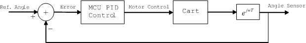
[Delay
block inidcated by e^(jwT) term]
As
long as one adheres to the setup procedures, anyone can operate
the inverted pendulum balancer. The procedure is as follows:
1)
Connect 5V and 12V power lines to correct pins on the circuit
board.
2)
With both power supplies off, balance the pendulum on the car.
3)
Turn on the 12V supply to power motor.
4)
Turn on the 5V supply to allow initialization of encoder.
5)
Gently tap the top of the pendulum in any direction.
See
a video of the inverted pendulum balance for ~8 seconds
The
device will not interfere with any other device in the room. The
only high-frequency device on the board is the 16 MHz crystal,
whose leads are short with capacitors to ground, to keep all noise
at a minimal. The RF circuitry of the RC car is disabled so as
to not interfere with anyone else’s circuitry, let alone
our own. Finally, the PWM signal is at such a low frequency (208.3
Hz) and passes through shielded cable such that it would not radiate
to interfere with anyone else’s circuit. Note: These frequencies
are not the same as those being transmitted by students with RF
projects. This virtually ensures no interference between projects.
The
metal rod used as a pendulum can create a dangerous situation
when placed on a moving vehicle. Therefore, we request that all
observers respect a 10’ safety zone. In addition, a software
safety feature is implemented to apply the break to the motor
if it travels in one direction for more than 2 seconds without
changing directions or if the MCU processes that the pendulum
has fallen more than 40 degrees.
What
We Would Do Differently Next Time
Assuming
the budget constraint is not removed, we would choose our car
more carefully, and base the decision not only on response but
also on mechanical design and stability (rocking, suspension,
etc). The pendulum would be reinforced such that movement would
be restricted to the vertical plane, with no rotational movement
in the pendulum, which causes excess pressure on the encoder and
possible erroneous sensor readings.
Our
entire design process revolved around what we had learned in MAE478.
Towards the end of the semester (and the end of the project),
the feedback course began moving from system analysis to controller
design and system modeling. Using techniques that we had learned
towards the end of the semester in the initial design phase (in
the middle of the semester) would have certainly created a more
robust and precise controller. The ability to model the mechanical
system, to use grey-box analysis (rather than black box analysis),
and apply bode plot and root locus design to create dominant poles
and zeros that make the system perform the way we want it to would
also have made for a more fulfilling design process, where more
knowledge between the two courses could be integrated. Finally,
the noise issue was dragged out for about 4 days while we tried
quick fixes to our original board. The minute this problem was
observed and the noise on the ground line viewed with the oscilloscope
(which showed very high noise spikes around 1V in amplitude),
the new board design (with isolated MCU and motor circuitry) should
have been adopted. This would have given us more time to fine-tune
the PID controller and maybe smooth out some mechanical bottlenecks
that prevented us from longer balancing time.
Conclusion
Throughout
the project, our one worry was that the car/motor’s response
was not good enough for our desired task; this was in fact true.
The car could not balance the pendulum indefinitely. Slippage,
originating in both the gear train and the soft tires (in contact
with the floor), would create a delay in our system that eventually
drove it to instability. The delay made it impossible for the
car to catch up, even though its velocity computations were correct.
However, while we could not balance the pendulum indefinitely,
the limited balancing achieved our main objective, which was to
balance the pendulum. The amount of time for which we balance
is out of our hand with our current budget, yet the prototype
clearly shows that the project can be done, albeit with quality
parts. We are confident that by using our circuit and logic on
a more sound mechanical setup and obviously adjusting PID parameters,
the system can achieve the ultimate feat of indefinite balance.
All
aspects of the design were our own. Of course ideas were taken
from MAE478’s feedback control labs, yet they were not implemented
in the same fashion. In addition, we did request outside help
from persons with a Mechanical Engineering background in our vehicle/pendulum
design. The code and circuit implementation of the design were
our own. We did not have time, however, to fabricate the stand-alone
board. Since we needed a prototype anyway, a perf board circuit
was made and after numerous hours of soldering and debugging the
two different circuits (single vs. dual power supplies), we decided
that time would be better allocated in fine-tuning the PID controller
rather than fabricating a board.
Despite
the short timeframe of ~1 month and the mechanical hurdles encountered,
we are pretty happy with the amount accomplished. The project
was a continuous learning process and it turned out to be one
of the most rewarding experiences at Cornell.
Code
of Ethics Checklist:
1. To accept responsibility in making engineering decisions
consistent with the safety, health, and welfare of the public,
and to disclose promptly factors that might endanger the public
or environment.
Our
inverted pendulum balancer can be a hazard to others standing
within the immediate vicinity of its path of motion. To that
end, we request that all observers maintain a 10’ safety
distance even with our 2 Sec. motor safety check, that is, if
the motor is rotating in the same direction for more than 2
seconds, or the pendlum reaches an angle greater than 40 degrees
from reference, a safety stop is executed.
2.
To avoid real or perceived conflicts of interest whenever
possible, and to disclose them to affected parties when they
do exist.
During
the Spring 2003 semester, another group attempted to balance
the inverted pendulum. While some may find it in our interest
to see our project succeed and out-perform theirs, our philosophy
was to help all groups with any questions they might have. Therefore,
we fully disclosed our method of angle detection to the other
group. We recommended to them that their potentiometer method
may not have enough resolution to detect an accurate angle error,
and that they may want to borrow an encoder from the MechE.
Dept.. In addition, we showed them how to isolate the motor
from the MCU with optoisolators.
3.
To be honest and realistic in stating claims or estimates
based on available data.
Our
original goal was “to build and implement an inverted
pendulum balancer, in the vertical two dimensional plane, using
PID control. Proportional-Integral-Derivative(PID) feedback
control will be implemented using a microcontroller, which will
sense a tilt of the pendulum and govern a motor to balance the
inverted pendulum.” (HW6 - Project Proposal)
There
was no claim of time-frame which the pendulum will balance.
We succeeded in balancing, yet could not achieve the ultimate
task of infinite balance due to the inferior motor/car.
4.
To reject bribery in all its forms.
There
was no bribery involved in our project. No person had anything
to gain by our successful completion of the inverted pendulum
balancer, nor did we have a motive to bribe any person as our
project worked and we were under budget.
5.
To improve the understanding of technology, its appropriate
application, and potential consequences.
Through
our website, we hope to have the ability to reach all those
interested in basic feedback control and practical engineering
using microcontrollers and various salvageable parts.
6.
To maintain and improve our technical competence and to
undertake technological tasks for other only if qualified by
training or experience, or after full disclosure of pertinent
limitations.
The
entire project was a learning process. Our technical competence
improved with every line of code written, every IC soldered.
From identifying the special features of the Atmel Mega32’s
PWM capabilities, to understanding how to isolate a noisy motor
from a sensitive MCU, we learned from each mistake made.
7.
To seek, accept, and offer honest criticism of technical
work, to acknowledge and correct errors, and to credit properly
the contributions of others.
Criticism
of our design was always welcome. Many people thought of different
ways to make our pendulum balance longer. Most ideas, however,
were contrary to all understanding of balancing an object easier.
Yet some criticisms were very helpful. For example, Prof. Land’s
help in isolating the motor from the MCU was probably the most
helpful step in moving from separate motor and encoder testing,
to motor, encoder, and MCU integration.
8.
To treat fairly all persons regardless of such factors as
race, religion, gender, disability, age, or national origin.
This project
shows that two people of different religion, disabilities, age,
and national origin, can work together to achieve a common goal.
9.
To avoid injuring others, their property, reputation, or
employment by false or malicious actions.
At
no time did we perform any malicious actions towards any group
in the ECE476 lab. This directly relates to the conflict of
interest code mentioned above. We did, however, encounter malicious
acts towards us, where someone (accidentally or purposefully)
knocked down our accelerometer with Op-Amp daughter board and
stepped on it. Luckily, we switched to the optical encoder and
did not need the accelerometer.
10.
To assist colleagues and co-workers in their professional
development and to support them in following this code of ethics.
As
mentioned above, any persons in the ECE476 lab that came to
us for help, be it with motor questions or stand-alone board
issues, received our help promptly and courteously.
Appendix
I: Program Listing
Motor
tester code: test_motor.c
Sensor
tester code: test_sensor.c | test_sensor2.c
Controller
code without PID: controller.c
Controller
code with PID: balancer.c
Appendix
II: Schematics
Figure
1: Simple
Motor Switch
Figure
2: Stand-alone
Board Schematic
Figure
3: Mechanical
set up of pendulum pivot and encoder
Figure
4: PWM output of
Timer 1
Figure
5: Code flow sequence
Figure
6: Encoder
channel output from usdigital.com
Image
1: Radioshack
Grinder Monster RC Truck from RadioShack.com
Image
2: US
Digital Optical Shaft Encoder S1 [one on left] from usdigital.com
Image
3: Pendulum
Pivot and Encoder Shaft #1
Image
4: Pendulum
Pivot and Encoder Shaft #2
Image
5: Stand-alone
board with one power supply
Image
6: Stand-alone
board with two power supplies #1
Image
7: Stand-alone
board with two power supplies #2
Image
8: Stand-along
board with two power supplies #3
Image
9: Inverted
Pendulum Balancer [cart/circuit/pivot]
Image
10: Inverted
Pendulum Balancer [overall picture]
Image
11: Inverted
Pendulum Balancer [mounted cirucuit]
Video:
Inverted Pendulum Balancer
[balances for ~8 seconds]
Appendix
III: Parts List
(1)
Atmel Mega32 Microcontroller [lab]
(1)
16 MHz Crystal [lab]
(1)
National Semiconductor LMD18200 H-Bridge [sampled]
(1)
Radioshack Grinder Monster RC Truck (Catalog #: 60-4311) [$11.97]
(1)
US Digital Optical Shaft Encoder (S1-1024-IB) [borrowed from MAE
dept.]
(3)
Optoisolators (4N35) [lab]
(1)
110V 60Hz AC to 12V DC transformer (1500mA max) [lab]
(1)
6"x2-1/16" PC Board [lab]
(1)
Mini slide switch [$0.35 from Jameco #204142]
(5)
.100" Straight Male Headers [$0.16 each from Jameco #108337]
(4)
Wire with 2 pin female connectors [$1.00 each from lab]
(X)
Various resistors, capacitors, and wires [lab]
(1)
7-3/4"x6"x1/4" Plexi glass [scrap]
(2)
L-shaped metal [scrap]
(1)
metal rod [scrap]
(4)
threaded rod [scrap]
(X)
Various screws and nuts [scrap]
TOTAL
COST: $17.12 < $25.00 Budget
Appendix
IV: Task List and Distribution
•
Mechanical assembly of pendulum on the cart - Eitan
•
Circuit layout and soldering - Eitan
•
Coding and documentation - Kenji
•
Testing and debugging - Eitan and Kenji
•
Project documentation - Eitan and Kenji
Special
Thanks to:
Mr.
Beny Sherer for help with mechanical assembly and various advice.
Mr.
Eryk Nice for lending us the encoder and helping us with PID control.
Professor
Bruce Land for all the advice and support.
All
our friends and family for putting up with our complaining.
All
the doubters for the extra motivation to proving you wrong. =)
Josh
for his box...
Appendix
V: Reference
Atmel
Mega32 Datasheet
National
Semiconductor H-Bridge Datasheet
US
Digital Optical Shaft Encoder Specs
Optoisolator
(4N35) Pinout
Stanford
Univ. EE281 Project: "Self-Balancing Robot" by Geoffrey
Bainbridge
|