![]()
|
|
|
|
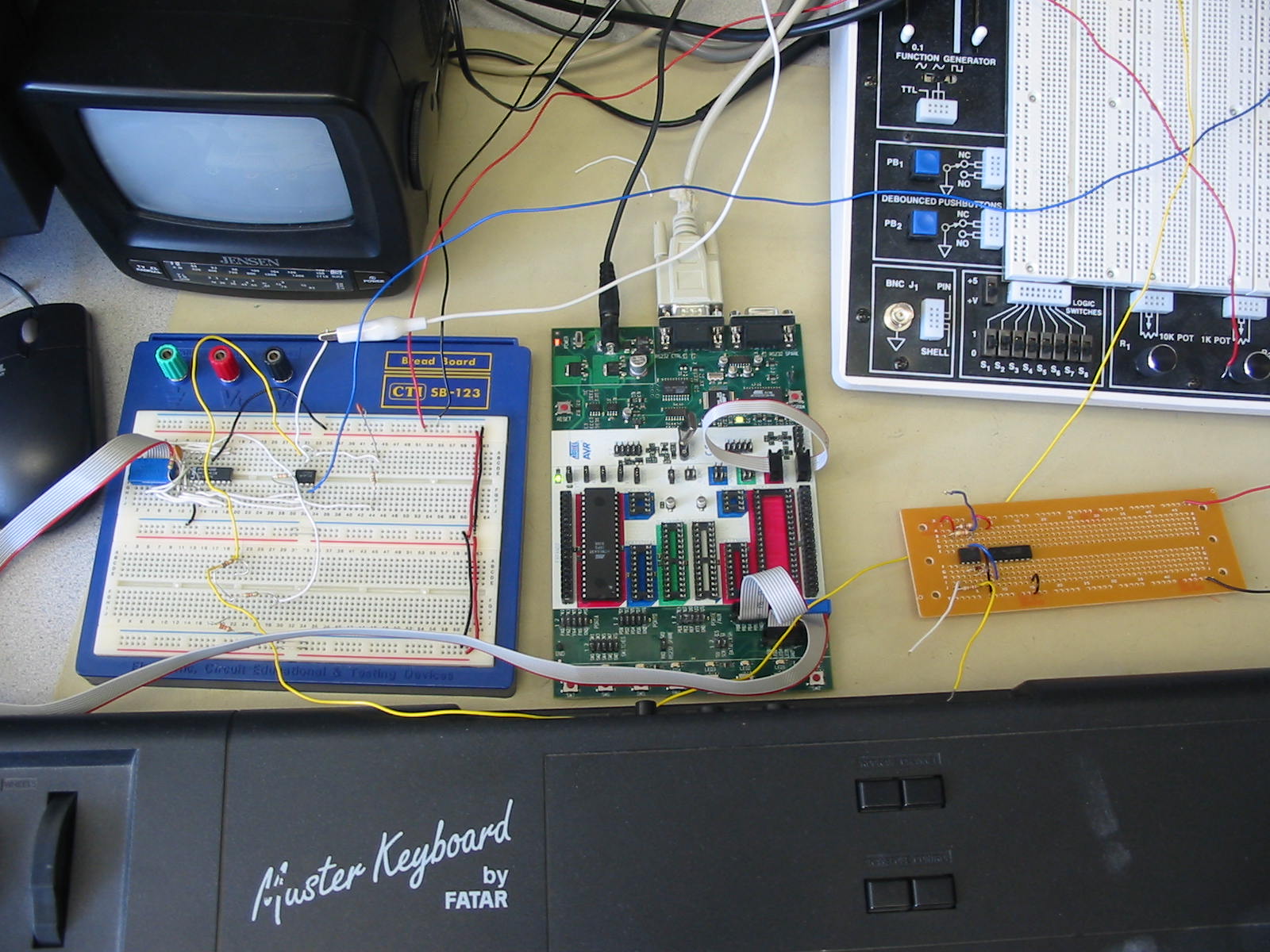
Project Idea Our first idea for this project was to take an old keyboard and rewire it to use the microcontroller to generate sound to our own set of speakers. Our TA then suggested we decode the output of a MIDI keyboard and produce an appropriate sound. Our project is specifically designed for the Studio 610 plus keyboard by FATAR. This was the only MIDI device we had access to so we could not make our MIDI decoding scheme any more general. Our synthesizer is not guaranteed to work unless it is hooked up to this specific keyboard. Project Structure The overall setup of our project goes like this: Keyboard Press ----> MiDI output ----> optoisolator ----> UART ----> code to pick correct note ----> DAC ----> low-pass filter ----> TV-speaker.
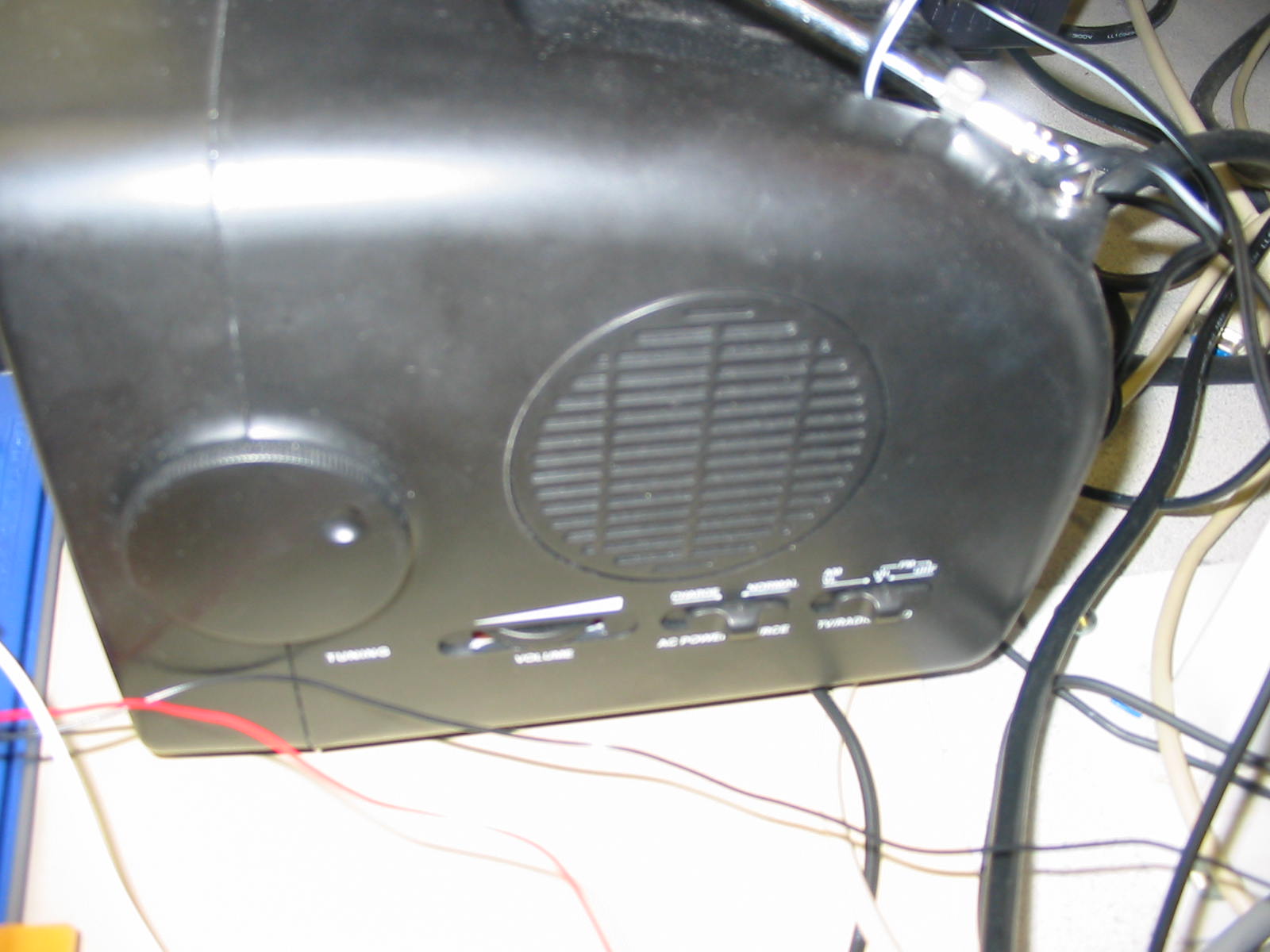
When a key is pressed on the keyboard, many different bytes of important data are sent out of the MIDI port. Most MIDI messages consists of three bytes. The first byte is a status byte and tells us what action is going on. Things such as note on and note off are examples of status bytes. The second byte recieved when a key is pressed is the value of the key that was pressed. Having this information allows us to be able to look up the correct note frequency corresponding to that key press. The description of how we make sound is found in the next section. The third byte is the velocity byte. We need this to detect when a key is released. When a key is released on this keyboard, the velocity byte goes to zero. When we see a zero in the velocity byte corresponding to a note we are currently playing, we then turn off that note. After the proper frequency is selected by decoding the MIDI, we output the 8-bit sinewave we have to the 8-bit digital to analog converter (DAC0808). The DAC0808 turns 8 different digital signals into one analog current. We then use an current to voltage amplifier op-amp to produce an analog voltage that can be plugged into a speaker. We also used a low-pass filter to clean up some of the higer unwanted harmonics in our signal. For a speaker, we chose to use the small TV's speaker as this already had a built-in audio input.
Sound generation OUR UNDERSTANDING OF HOW SOUND IS PRODUCED Hardware/software Tradeoffs We use both hardware and software to implement our synthesizer. Our software is the real heart of our project which does all of the real computing. Our hardware is mostly used for to convert the output of the Keyboard into a readable signal for the MCU, and also to convert the output of the MCU into a playable signal for a speaker. |
|
|