Hardware Design
A detailed circuit schematic of our entire hardware setup can be found in the Schematics page.
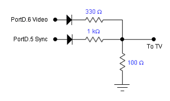
All of the video content that was displayed on the television screen was first output digitally by the MCU. Since a television runs off of analog video signals, a 2-bit digital to analog converter (DAC) was required to convert the digital signals coming from Port D of the MCU (see circuit schematic) into analog signals that the television could interpret. The construction of this DAC can be found below:

This DAC allowed us to produce the voltages that were required to properly display content on the television. More specifically, the sync level had to be 0 volts, the black level had to be 0.3 volts, and the white level had to be 1 volt. The above DAC provided us with a way of converting the 0 or 5 volts that was output by a port pin to one of these television voltage levels.
The Sega Controller was adopted for this project because of its relative ease to be connected to a standard port on the STK-500. We purchased a 9 pin male D-Sub connector, soldered it to 9 wires, and connected the wires to a protoboard, which was connected to Port C of the STK-500 as explained below. Once the male D-Sub connector was connected, the game pad could then be installed and removed as easily as plugging it into the original Sega Genesis console.
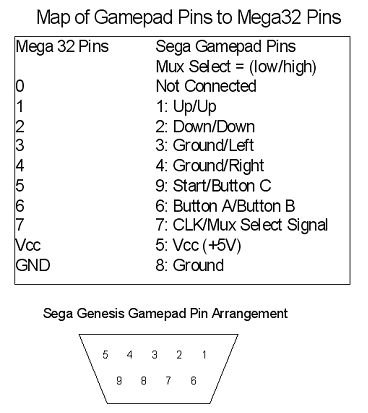
The functionality of the Sega Genesis controller can be understood very easily. The 3-button Sega Genesis controller uses a CMOS switch/multiplexer design that makes it easy to detect any button press. A female 9-pin D-Sub (DB9) connector is located at the end of the cable connected to the Sega controller. The functionality of each of these 9 pins can be summarized below:

It can be noticed that all of the output pins on the controller are simply the output of a basic multiplexer. Therefore, to select between different sets of buttons on the game pad, the mux select bit, pin 7 can be switched high or low. During game play, the mux select bit was set high so that all the directional buttons of the game pad could be used. Whenever the start button is needed for the title screen, the mux select was set low. These are two examples of when the mux select bit was switched for different functionality in the game.
Difficulties
A difficulty we encountered during the incorporation of the Sega Genesis game pad into our game was debouncing the controller. Starting with the typical debounce algorithm which has been used in the previous labs, the game pad experienced stalls. When buttons were pressed, the game did not always respond. After examining the connection of the game pad with the port D ribbon, we suspected that because pin 0 of the game pad was not connected to anything, it could have a floating voltage and therefore may interrupt the internal electronics of the controller. As a result, we decided to connect the pin to ground, and the game pad had become more responsive but still inconsistently ignored button presses.
Upon further examination of the debounce code, we determined
that the condition that was used to detect a pushed button was verified
as false when in fact it was supposed to be true. We attempted to logical
OR the two binary bit patterns that represented the idle states of the
game pad to determine when the button was pushed. This approach would
have allowed us to handle both cases when no buttons were pushed. When
the mux select bit was set low and no buttons were pressed, the pins output
a binary value of 01100110; when the mux select bit was set high, the
idle the pins output 11111110. We rewrote the code such that there were
now two separate debounce state machines, one for the mux select high
and one for the select low configuration. This had solved the problem
and the game pad now successfully transmitted each button press. Rather
than debugging the problem for hours, we decided to keep the two debounce
machines and move on.
