| Introduction | High
Level Design | Program/Hardware Design | Results
of the Design | Conclusions |
| Appendices | References
|
Single sentence summary
A programmable laser light show that allows the user to specify the
pattern displayed via three motor speeds and the length of time that this
pattern is held.
Project Summary
For this project, we designed a system to guide a laser beam through
an array of three rotating mirrors and then project it onto a screen where
it is able to “draw” a range of different patterns. Allowing
the mirrors to rotate at variable speeds creates the different patterns.
These variable speeds of the motors are produced via pulse width modulation
(PWM) control from the MCU. Each motor has its own dedicated pulse width
modulator, allowing each motor to rotate at a different speed.
Our project can be broken down into a few major constituent components.
These components include the laser tube and high voltage power supply,
the mirror assembly (three circular mirrors and motors), the Atmega32(L)
(and STK-500), and finally a custom made board which contains the PWM
support circuitry. All of these components are mounted on a piece of pegboard
making the unit easily portable. Additionally, a user interface for the
motors has been implemented that uses HyperTerminal. Each one of these
components is discussed in detail below.
We decided on this project after discussing the types of potential projects we could complete and jointly decided that since we never dealt with any type of motor control in lab that the final project was a good opportunity to do so. Additionally, after a trip last summer to Darien Lake amusement park where we watched a professional laser light show, we both had wondered how exactly this type of presentation was done. After a bit of research, we concluded that for the time allotted for this project, this tri-mirror setup was the most feasible.
| Introduction | High
Level Design | Program/Hardware Design | Results
of the Design | Conclusions |
| Appendices | References
|
Rationale and sources of your project idea
To develop the idea of this project, we first built the system using hardware only. The system was the same as in the final design with the exception that all motor control was done with potentiometers instead of PWM control. This allowed us to experiments with different numbers of mirrors, different ranges of speeds and different arrangements of the mirrors themselves. From this experimentation, we were able to make many decisions regarding the way the final project should be constructed. Firstly, we decided on three motors/mirrors for a number of different reasons, the main reason being that we could maximize the number of patterns available for display by maximizing the number of mirrors. The Atmega32(L) contains four pulse width modulators from three timer sources. One of these timers must be dedicated to program control, this leaves a maximum of three PWM channels from a single chip. Hence, we decided that three mirrors and motors was the proper choice.
Once we established that we could control three motors to make a pattern,
we tried to think of a way that we could incorporate more of the microcontroller’s
capabilities into our design. We thought of the light show idea next.
We could extend the idea of motor control by using serial communication.
A user could specify the motor speeds and the pattern to be held. This
show concept required an extensive user interface, which we had to design.
At this point, all timers had a task assigned to them. We thought that
this idea was complex enough to appropriately challenge our design skills.
Logical structure
We visualized this project in three parts. First, we had to successfully implement control of an individual light pattern. In our user interface, we added an option to make a light pattern. The user can enter a speed for each of the three motors to specify a light pattern. This pattern will be held until the user decided to quit the program. This was the first logical component of our project.
Next we adapted the individual light pattern module to design the light
show component. We used three arrays to specify the three motor speeds,
and a fourth array to specify the time that the pattern is held for. For
example, index zero of array 1,2,3 specifies the speed for each of the
three motors. The zero index of the time array specifies the length of
time that the speeds will be held for. After this length of time (in seconds)
has expired, the next stored pattern is displayed. When the end of the
show arrays are reached, a message alerts the user that the show has concluded,
and all three motors shut off.
Lastly, we took these four arrays and enabled the user to store them in EEPROM. In this manner, a light show can be restored, even if the system is powered down. In the user interface, there are options that allow a user to save and restore a light show.
Hardware/software tradeoffs
One of the tradeoffs that we needed to weigh during the design of this project was the choice of using all hardware PWMs or needing to code a single PWM in software while the other two were done in hardware, as our original proposal suggested. For instance, a slightly less expensive chip could have been used, such as the mega163, but then only two hardware PWMs would have been available since timer0 would have still needed to be used as the task timer. While writing a software PWM itself is not complicated (it only requires the manual toggling of a single output port bit), calibrating the modulation frequency to coincide with the frequency of the other two hardware PWMs may have proven to be a tricky procedure. Another tradeoff that we needed to consider was how much EEPROM would be available for on-chip laser show storage. The mega163 had 512 bytes while the mega32 has 1024 bytes which for the storage of our four arrays (three speed arrays and one timing array) which makes a significant difference. With these two metrics in mind, we felt that the Atmega32(L) was the proper choice of MCU.
| Introduction | High
Level Design | Program/Hardware Design | Results
of the Design | Conclusions |
| Appendices | References
|
Hardware Design
As mentioned earlier, the hardware dimension of our project is composed of three main parts: a laser tube and high voltage power supply, a spinning motor/mirror assembly, and the support circuitry for the PWM motor control. Each one of these parts is discussed in detail below.
I) Laser Tube and High Voltage Power Supply
The laser tube we have chosen is a continuous beam, 0.9mW, red argon laser
tube. The particular beam was chosen because of its high brightness and
minimal spreading and also because the large tube was easy to mount and
hold steady. This is crucial because jitter from the mirrors could cause
the laser beam to randomly bounce around, making the show appear sloppy.
The tube is a cylinder and is mounted with U-brackets onto the pegboard
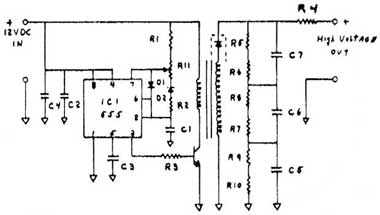
(see Figure 2). The laser runs on a 14,000V power supply which steps up
from 12VDC. We have constructed this power supply from scratch by following
a schematic of an existing high voltage laser power supply (see appendix
II). This supply is based around a switching flyback transformer run by
a 555-timer IC. No modifications were made to this original schematic.
The 12VDC comes from a separate power supply that plugs into a standard
110VAC wall outlet.
II) Mirror Assembly
This assembly consists of three identical motors, each equipped with a
mirror mounted perpendicular to the end of the rotating motor shaft, as
shown in the side view below (note that the reflective surface of the
mirror is facing away from the motor shaft):
Figure 1: Motor Assembly
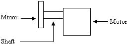
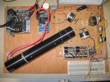
The motors are 6V, continuous DC motors that run from an external 6V battery pack comprised of 4 series connect C-cell batteries. The mirrors are flat and circular in shape measuring 1 1/4” in diameter and 1/8” in thickness. Mounting the mirrors to the motor shafts was done with a specialized epoxy that allows for high-speed rotation of the mirrors. The motors are attached to the pegboard with small bolts to prevent any rotation of the motor body itself. The combined laser and spinning mirror assembly is pictured below in figure 2:
Figure 2: Laser and Spinning Mirror Hardware Assembly
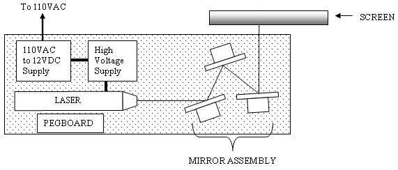
Also pictured in the diagram above is the project is the projection screen. This screen was made from two custom made L-brackets, a length of threaded steel rod, and some spare window shade vinyl. The screen can be removed if the user wants to display the show on a bare wall.
III) Pulse Width Modulation
General Discussion of Concept
Motor control via PWM signals is one of variety of standard ways in
which a motor’s speed can be precisely controlled. The idea of PWM
control of a motor is analogous in a way to a light switch/light bulb
system. If over the course of a unit of time the light switch is off for
the entire time, then the bulb will be dark. Conversely, if the light
switch is on for the entire time, then the bulb will be as bright as possible.
However, if one was to rapidly flip the switch (on, off, on, off, etc.),
depending on what percentage of the cycle the switch was on (the duty
cycle) the light could be made to shine at a range of intensities between
100% dark and 100% bright.
Generalizing this concept to the idea of motor control, the Atmega32 has
the ability to produce signals that look like the following:
Figure 3: PWM Control Signals
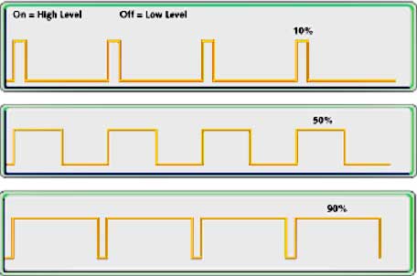
The top most signal represents a slow speed because 90% of the cycle
the motor is off. The middle signal represents half speed because the
on and off times are balanced (50% duty cycle). Finally the bottom signal
represents a high speed because 90% of the cycle the motor is on. Although
the signals are fluctuating rapidly, the behavior seen from the motor
is very smooth because the inertia of the rotating shaft provides a natural
smoothing effect (like the flywheel in a car). However, additional smoothing
of the signal can be added in the support circuitry, discussed later.
The only point left to discuss is how the signals actually drive the motors.
The motors we are using need more voltage than the STK board can supply,
so an external battery pack is used to supply this power. In order to
use the Atmel PWM signals to modulate this external power supply, 2N2904
high-speed switching transistors are used. Going back to our light bulb
analogy, if you were the one flipping the switch, than your hand would
represent the PWM signal from the STK board and the switch would represent
the 2N3904. The battery pack would be analogous to the 110VAC used to
drive the load (light bulb, motor).
Implementation
This project will require three pulse width modulators to drive our three
motors. The mega32 offers three timers, each equipped with PWM capability.
Additionally, timer1 has two independent PWM channels that can be used.
We have chosen timer0 to be used for general timing tasks such as serial
communication and sound generation; hence it is timers 1 and 2 that are
used to generate the PWM signals for the motors. In all cases, the PWM
output lines will run from the MCU to external support circuitry, which
is discussed next.
Support Circuitry
Support circuitry is necessary for motor control because the MCU has neither
the voltage nor amperage to adequately drive the motors. Therefore, the
PWM output lines modulate the gates of three transistors that drive the
motors using an external power source. This general circuit is shown below:
Figure 4: PWM Support Circuitry
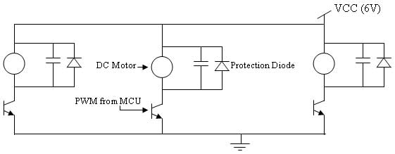
The rapidly varying PWM lines allow for smoothly varying motor speeds, which in turn allow for crisp laser images. Note that the protection diodes are needed because the changing magnetic fields in the inductive load will cause sharp spikes that would blow out the motors without these diodes. The VCC rail is powered by a 6V battery pack (4 C-cells). This is the final hardware component of our design project. A picture of the complete hardware system is shown below.
Program Design
Using HyperTerminal, we constructed a user interface that supports two modes. Mode 1 will allow the user to set the duty cycles of each motor individually. Once these duty cycles are set, they will be held until the user changes them. Mode 2 is a light show programmer. This mode allows the user to specify a series of motor speeds (that determine a light pattern) that is held for a user-determined amount of time. A more detailed description of each mode follows.
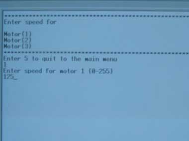
Mode 1: Independent Duty Cycle Control
In this mode the user is prompted to select one of the three motors and set its speed. The user sets the speed by entering a number between 0 (off) and 255 (100% duty cycle). This range of numbers is a result of us choosing to use 8-bit PWM. Note that due to loads on the motor shafts (mostly weight of the mirror) we are unable to utilize the full range of speeds. This is discussed later on. The user must set one speed at a time, but can specify different speeds for each motor. The speeds are held until the user quits out to the main menu. The picture below shows what the user-interface menu looks like.
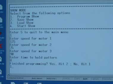
Mode 2: Laser Show Programmer
This mode allows the user to setup a laser show. The user has several options in this mode. The first option is to program a new laser show using the “program show” option. The user will be prompted for a set of three duty cycles, one for each motor. This will specify a particular laser pattern. The user will also be asked for a length of time (in seconds) that this pattern will be held. Each of the four values will be stored in separate arrays. Once this input set is complete, the user will be asked whether they are done entering data. If not, then they will be prompted to enter in four new values for the next pattern. If data entry is complete, they return to the programming menu. The user now has the options of either running the show or saving to EEPROM to be used at a later session. If the user selects “save show”, the arrays will be stored in EEPROM, so that at power down, the show will be saved. When the system is turned back on, the user is able to select the “load show” command and restore the saved show. Once a show is entered or loaded back from memory, the user may select the “start show” command. This option immediately spins up the motors to the speeds specified in the first data set. Each successive pattern is displayed and held for the specified amount time until the final data set, after which the motors are shut off. Below, menu 2 is shown, along with the information the user is prompted for while programming a show.
Code Structure
The purpose of this section is to explain, in some detail, the workings of our code. Very low-level detail will not be discussed here, but can be examined in our commented code in Appendix A. This section will provide the reader with enough detail to be able to follow the commented code.
At reset, an initialize function is called in which all state variables,
indices, LCVs, etc. are set. This function is also called if the user
presses ‘5’ at any of the mode menus. There are only two major
components that are present in our while loop in main. The first sets
up a one second counter. This counter is only run while a laser show is
displayed. The counter in main increments whenever the ‘time’
variable reaches zero (it starts at 125). This indicates that one second
has elapsed. Once the counter reaches the user specified time length,
the next laser pattern is displayed.
The other component that is run from main is our control flow function.
This function is really the heart of the user interface. From here, user
input is received and decoded. Based upon several state variables and
the user input, the appropriate actions are determined.
A function called get_input is used to assign commands. USCRA bit 7 is
examined first. If it is high, then there is a character waiting to be
processed. The function then checks if the character is a carriage return.
If it isn’t, then it is added to a character input array. If the
entered command is a carriage return, then the character array is concatenated
and type cast into a character. This character is stored in the ‘command’
variable. In addition, a variable ‘process’ is set high. This
will be used as an indicator that there is a valid command ready to be
processed by the control flow function.
The principle state variable used is called ‘menu_page’. It
takes on one of three values. It is zero on reset, one if in independent
duty cycle control mode, and two if in show programmer mode. Based mostly
upon the value of ‘menu_page’, the appropriate menu is displayed
to the user.
Based upon which menu is currently displayed, the current command, and
some other state variables, an appropriate action is taken. For example,
process is frequently used to ensure that menus are only displayed once,
and not endlessly repeated onscreen. ‘enter_motsp’ is used
during the individual PWM control mode, and ensures that the user is prompted
for the appropriate information. ‘Programshow’ is used to
determine when the user is entering data to be stored in the laser show
arrays. It also helps ensure that the user is prompted for the appropriate
data.
After reading the above description, it becomes clear that one of our
principle tasks in designing this interface was to keep track of ‘where’
the user was. By using state variables, we had to ensure that all data
was assigned to the appropriate variables, and that the program did not
take unwanted actions.
Hardware/Software Implementation Problems
As with all major design projects, we encountered several difficult
and unexpected problems. First, after we successfully got the PWM working,
we noticed that we could not get the full range of speeds (0-255) with
the motor. When the motors are first started up, they need a speed of
at least 65 to get the motor shaft to continually turn. Once the motor
is started, speeds can be dropped lower than 65, but usually not much
below 35. Although we were initially concerned with this performance aspect,
after testing we determined that this was not actually a problem. At such
low speeds, the motors are not even able to move the beam fast enough
so that the persistence of vision takes effect. At these low speeds, the
laser just appears as a moving dot, rather than a coherent pattern. We
are still able to get a full range of patterns even without the full range
of speeds.
We also encountered some problems with ground. As we tested our design, we noticed that sometimes the motors would not fully shut off at zero duty cycle and power down, or that tapping the shaft could restart them. After some investigation, we determined that there was about a 2-volt peak-to-peak sine wave present at ground. We ensured that both the evaluation board’s ground was common with the battery-pack’s ground. This did not have any effect. After further experimentation, we found that the only way to rid ground of this unwanted signal is to make both grounds common, and connect them to earth ground (through the scope or wall socket).
| Introduction | High
Level Design | Program/Hardware Design | Results
of the Design | Conclusions |
| Appendices | References
|
Speed of execution
Our biggest concern was ensuring that any command entered by the user was processed correctly. We made sure that we used non-blocking code for this input. When the user enters a command in HyperTerminal and hits carriage return, a flag called “process” is set high. The software uses this flag to indicate that there is a command ready to be processed. A long series of if-else and case statements determines and executes the appropriate action. We were somewhat concerned that this conditional chain may be so long that some user input would be missed. However, after some extensive testing we found that our software always accurately processes user input. Our other concern was that the PWM techniques that we used would provide a suitable level of sensitivity to the motors. We wanted to ensure that a full range of speeds was possible, thus allowing for the greatest variety of laser light patterns. We accomplished this mainly empirically, using 8-bit modulation and then checking the motor operation to ensure that a wide variety of speeds were possible.
Accuracy
Accuracy, although important, was not a major consideration in our design. We wanted to make sure that the patterns in the show mode could be displayed in some length of seconds. We used a counter to keep track of the number of seconds that has elapsed. Once this counter equals the desired display length for the pattern, the second counter is reset and the next pattern is displayed. If we are off by some small number of milliseconds, the error will not really be noticeable to the user, nor will it affect the overall appearance of the light show. The only other accuracy consideration was to ensure that all commands entered in HyperTerminal were properly received. The methods we used to ensure this have been discussed previously in the speed section.
Safety
There are several safety concerns involved in this project. The first
is that project involves a laser so basic laser safety concerns need to
be addressed. While the beam is certainly not high power, it is still
dangerous if pointed directly into one’s eye. Most of the time the
beam is simply directed through the mirror array and onto the screen and
posses no real threat. However, during alignment of the mirrors the laser
must be on and the beam could accidentally strike someone in the eye.
Care must be taken, especially during alignment, to make sure that the
beam does not become a hazard.
Another concern is the high voltage being used to operate the laser tube.
Because we constructed the supply from discrete parts and the unit is
not packaged up, it was important to make sure that it would not be easy
for someone to accidentally stick their hand in the unit and get injured.
We took several precautions to try and avoid this. The flyback transformer
we used is a commercial unit that is encased in plastic, as are all capacitors
and other high voltage components. Also, any observable external contacts
carrying either high voltage DC or 110VAC were covered with electrical
tape to shield them from accidental contact.
Interference with Other People's Designs
We didn’t believe that our project caused any noticeable interference, since we ran it for a couple days without causing any problems for our surrounding neighbors. However on one of the last days, we did encounter one problem. One group was doing a guitar tuner of some kind, and noticed that our project created some noise that was detectable on his system. Apparently, the PWM signals that came off the MCU caused this problem. We were a little surprised by this, as we thought that our laser power supply would be the likely culprit. However, the interference was not generated when the laser supply was on. We guess that the wires that connect the output pins on the evaluation board to our circuitry are causing this noise. Fortunately, the interference was not so severe as to create a serious problem for our classmate.
Usability by You and Other People
A major component of our project was to create a user interface that would be robust and easily understood. We believe that practically anyone could use our design. The most difficult aspect of our design would be the setup, which anyone who has taken 476 could do. Setup merely involves setting up HyperTerminal. Once the project is set up, anyone could use the interface. The hardware is ready to use, so the only thing the user must do is turn on the power supply. From there, it is a simple matter of selecting the desired option, and inputting a motor speed. We thought about making the project ore portable by using an LCD to display the interface, however we decided against it because we thought it would be significantly less user-friendly.
| Introduction | High
Level Design | Program/Hardware Design | Results
of the Design | Conclusions |
| Appendices | References
|
We were able to meet all of our major design goals, as set forth in
our project proposal. The secondary goal, sound, was not implemented due
to lack of time. However, we are extremely pleased with the way that our
project turned out. Our resultant product is a great demonstration of
the Atmel32’s capabilities with motor control and serial communication.
Our project utilized most of the chip’s resources including all
three timers, the UART, and EEPROM storage. Further, we are very pleased
that the project is fun to operate. It is very entertaining to explore
the different patterns possible, and then program in a show that demonstrates
some very interesting light patterns. If we had to implement this project
again, we would do several things differently. First, we would try and
make our code somewhat more organized. Although entirely functional, and
generally readable, we feel that had we done a little more work on paper,
the code could be more easily understood. There are not too many intellectual
property considerations with our project. We used readily available hardware,
including an argon laser, power supply, transistors, motors, and mirrors.
We did not have to sign any non-disclosure agreements to get any of this
hardware. Our code is of our own design, and not part of the public domain.
Our project is an interesting demonstration of how a simple laser light
show may be programmed. We do not feel that there are very many patent
possibilities because most commercial systems are far more advanced and
capable of many more designs. Smaller systems are marketed that are similar
to ours except for the fact that they use glavometers in place of motors
and are often able to accept RCA inputs so that the pattern changes with
the music. However, none of these systems to our knowledge allow the user
to preprogram the unit to display a certain series of patterns. This idea
might be worked in to allow some sort of patent potential.
Finally, we would like to demonstrate a few ways in which our project
complies with the IEEE Code of Ethics. Point one of the code states:
to accept responsibility in making engineering decisions consistent with the safety, health and welfare of the public, and to disclose promptly factors that might endanger the public or the environment
As stated before in this report, all major safety hazards have been assessed and avoided as much as was possible given the time span of this project. The high voltage supply was sealed up and labeled with a “high voltage” sticker so that observers would understand the threat. The entire unit was mounted securely to a board, minimizing the risk that someone could pick up the laser tube and cause injury to themselves or others with the beam. Also, despite the speed of the motors, the edges of the mirrors have been smoothed so that no sharp edges could cut a user who was trying to align the unit during operation. Point five of the code states:
to improve the understanding of technology, its appropriate application, and potential consequences
We have already mentioned how happy we were that this project placed a slightly different “spin” on the idea of the laser show in an application that is a bit different than standard laser shows. Large-scale laser shows tend to utilize devices that can accurately and quickly move the beam in both the x- and y- planes, hence being able to make any 2-D figure. Ours, while more simplistic, is also much cheaper and in some ways more elegant in its operation. The sensitivity of the patterns to the changing motor speeds is quite interesting and allows for a wide range of available patterns if the user is willing to experiment enough. We feel that this is certainly an appropriate application of the popular laser technology. Point three of the code states:
to be honest and realistic in stating claims or estimates based on available data
From the onset of this project we were honest as to our own goals and the ability of the system that we were creating. We were realistic with the budget that this project would run us and we made it so that the project worked as specified given the $25 limit. We referenced all parts of the design that we did not explicitly develop and were honest about the portions of the project that could not be completed due to lack of time. Finally, we were honest when discussing the limited potential of patenting this device because of it similarity (though not exactly) to some existing laser projection devices. Point seven of the code states:
to seek, accept, and offer honest criticism of technical work, to acknowledge and correct errors, and to credit properly the contributions of others
Our project without question complies with this portion of the code. As stated before, the high voltage supply was constructed from a design that was not ours and that design was certainly referenced in this report. Also, during the completion of this project we certainly stumbled upon many errors, of which some of the larger ones were discussed previously. For example, the problem with our circuit concerning the method of grounding was eventually identified (after hours of searching for it) and corrected. Also, Professor Land pointed out a few places on our power supply that were potentially dangerous and asked us to cover them with electrical tape, which we did immediately. Finally, throughout the design of this project we asked the TAs, Professor Land, as well as some of the other students for their input on the project and certainly took their input to heart. For instance our TA, Derek, certainly assisted us in choosing the proper switching transistors for the PWM control circuitry. Finally, point ten of the code states:
to assist colleagues and co-workers in their professional development and to support them in following this code of ethics
We feel that this point has a bit of dual meaning in the context of
ECE 476. The “colleagues and co-workers” applies both to the
partners working on the project together as well as the other groups working
around us in the lab. As a group, we tried our best to help out any groups
that asked us for advice or input because we expected to receive the same
sort of treatment when we asked them. Additionally, by working closely
together we were able to keep each other’s work at high standards
and make sure limited mistakes were made that could possibly violate the
code of ethics. For instance, this close working unit was the reason the
no limited safety issues remained when the project was complete. Also,
by helping each other out we were able to expedite the development process
and actually complete most of the goals that we set for ourselves.
In conclusion, we feel that our project was a success on several different
levels. It was a physical success in that we ended up with a working laser
show system that utilized a wide range of our own capabilities as well
as the Atmega32’s capabilities. It was a learning success in that
we learned a lot of different things about how to approach a project of
this magnitude and how we would approach it differently given a second
chance and/or more time. Finally, it was an ethical success as we showed
above in its compliance with the IEEE code of ethics.
| Introduction | High
Level Design | Program/Hardware Design | Results
of the Design | Conclusions |
| Appendices | References
|
Appendix I: Commented Program Listing
/****************************************************
ECE 476 Final Project: Computer Controlled Laser Show
Josh Silbermann and Matt Melnyk
Thursday, May 1st 2003
*****************************************************
*/
#include <Mega32.h>
#include <stdio.h>
#include <stdlib.h>
#include <math.h>
char current_char; //most recently entered character
char input[4]; //array that holds the command
char process; //set high when command recieved
char menu_page; //current menu page displayed
char show_mode; //high if running laser show
unsigned int in_count; //index for input array
char command; //concatinated input array
char mot; //selects motor that command refers to
char enter_motsp; //state variable that is high
when speed entered
unsigned char reload; //used to set time base
char time; //used to set 1-second timer
unsigned char motor1_show[25]; //speeds for motor1
in show mode
unsigned char motor2_show[25]; //speeds for motor2
in show mode
unsigned char motor3_show[25]; //speeds for motor3
in show mode
unsigned char showtime[25]; //pattern holding times
for show mode
char stage; //index into show mode arrays while
programming show
char programshow; //state variable that is high
when entering show mode data
char parse; //counter to ensure that all show mode
data entered
char max_index; //maximum index into show mode arrays
char run_time; //number of seconds elapsed since
pattern began
char index; //index into show mode arrays while
show running
char menu2; //control variable used to display menu
2
char y; //index variable used for eeprom assignment
char display_speed; //control variable to display
motor speeds in Hyperterminal
char display_end; //control variable to display
end-of-show message in Hyperterminal
//Variables used for power-down storage of data
eeprom char e_motor1_show[25]; //eeprom storage
of motor1 speeds
eeprom char e_motor2_show[25]; //eeprom storage
of motor2 speeds
eeprom char e_motor3_show[25]; //eeprom storage
of motor3 speeds
eeprom char e_showtime[25]; //eeprom storage of
pattern holding times for show mode
eeprom char e_max_index; //eeprom storage of max
index into show mode arrays
//Program functions
void display_menu0(void); //displays menu 0
void display_menu1(void); //displays menu 1
void display_menu2(void); //displays menu 2
void get_input(void); //checks for input and assigns
command
void control_flow(void); //master control function
void initialize(void); //initialize all variables
void start_show(void); //runs current show
//timer 0 overflow ISR
interrupt [TIM0_OVF] void timer0_overflow(void)
{
//reload to force 1 mSec overflow
TCNT0=reload;
//Decrement time if not zero
if(time>0) --time;
}
void main(void)
{
initialize(); //initialize variables
while(1)
{
if((time==0) & show_mode) //if running show,
use 1 sec time intervals
{
time=125;
run_time++;
PORTB.2=!PORTB.2; //1Hz timing flash
}
control_flow();
}
}
void display_menu0(void) //display menu 0
{
putchar(0x0c);
printf("*************************************************************************");
printf("\r\n");
printf("Welcome to the Laser light show user interface");
printf("\r\n");
printf("Please select from the following options");
printf("\r\n");
printf("1. Enter 3 motor speeds and make a light pattern");
printf("\r\n");
printf("2. Program a laser light show");
printf("\r\n");
printf("*************************************************************************");
printf("\r\n");
}
void display_menu1(void) //display menu 1
{
putchar(0x0c);
printf("*************************************************************************");
printf("\r\n");
printf("Enter speed for");
printf("\r\n");
printf("\r\n");
printf("Motor(1)");
printf("\r\n");
printf("Motor(2)");
printf("\r\n");
printf("Motor(3)");
printf("\r\n");
printf("*************************************************************************");
printf("\r\n");
printf("Enter 5 to quit to the main menu");
printf("\r\n");
}
void display_menu2(void) //display menu 2
{
putchar(0x0c);
printf("*************************************************************************");
printf("\r\n");
printf("SHOW MODE");
printf("\r\n");
printf("Select from the following options");
printf("\r\n");
printf("1. Program Show");
printf("\r\n");
printf("2. Save Show");
printf("\r\n");
printf("3. Load Show");
printf("\r\n");
printf("4. Start Show");
printf("\r\n");
printf("*************************************************************************");
printf("\r\n");
printf("Enter 5 to quit to the main menu");
printf("\r\n");
}
void get_input(void) //checks for input and assigns
command
{
if (UCSRA.7) //if character is waiting
{
current_char=getchar();
if(current_char != '\r') //check for carriage return
{
putchar(current_char);
if(current_char == 0x08)
--in_count;
else
input[in_count++] = current_char; //construct command
array
}
if(current_char == '\r') //check for complete command
{
input[in_count] = 0x00; //null terminate
putchar(current_char);
putchar('\n');
in_count=0;
process=1;
command=(char)atoi(input); //assigns command to
be processed in control flow
}
}
}
void control_flow(void) //master control function
{
if((menu_page==0) & process) //display menu
0 on reset
{
display_menu0();
process=0;
}
else if((menu_page==1) & !enter_motsp & process) //display
menu 1 when not entering motor speeds
{
display_menu1();
process=0;
}
get_input(); //gets command
if((menu_page==0) & (command==1)) //enter
individual motor speed setting mode
{
menu_page=1;
}
else if((menu_page==0) & (command==2)) //enter
show mode
{
menu_page=2;
menu2=1;
}
else if((menu_page==1) & (command == 1) & process & !enter_motsp)
//change motor 0 speed
{
enter_motsp=1;
printf("Enter speed for motor 1 (0-255)");
printf("\r\n");
process=0;
mot=1;
}
else if((menu_page==1) & (command == 2) & process & !enter_motsp)
//change motor 1 speed
{
enter_motsp=1;
printf("Enter speed for motor 2 (0-255)");
printf("\r\n");
process=0;
mot=2;
}
else if((menu_page==1) & (command == 3) & process & ! enter_motsp)
//change motor 2 speed
{
enter_motsp=1;
printf("Enter speed for motor 3 (0-255)");
printf("\r\n");
process=0;
mot=3;
}
else if((menu_page==2) & process & menu2) //for
proper displaying of menu 2
{
display_menu2();
process=0;
menu2=0;
}
else if((menu_page==2) & process & (command==1) & !programshow)
//begin to program show
{
programshow=1;
parse=5; //5 pieces of data to enter; 3 motor speeds,
hold time, finish program query
}
else if((menu_page==2) & (command==4) & !programshow) //run
current show
{
if(process) //for proper display purpose
{
printf("Enter 5 to stop show");
printf("\r\n");
show_mode=1;
process=0;
}
start_show();
}
else if((menu_page==2) & (command==2) & !programshow & process)
//save current show to EEPROM
{
while(y<=max_index) //copy show arrays to equivilant
EEPROM locations
{
e_motor1_show[y]=motor1_show[y];
e_motor2_show[y]=motor2_show[y];
e_motor3_show[y]=motor3_show[y];
e_showtime[y]=showtime[y];
y++;
}
y=0;
e_max_index=max_index;
menu2=1;
}
else if((menu_page==2) & (command==3) & !programshow & process)
//load current show from EEPROM
{
max_index=e_max_index; //prevents loading residual
data from longer shows
while(y<=max_index) //copy show arrays back from
EEPROM locations
{
motor1_show[y]=e_motor1_show[y];
motor2_show[y]=e_motor2_show[y];
motor3_show[y]=e_motor3_show[y];
showtime[y]=e_showtime[y];
y++;
}
y=0;
menu2=1;
}
else if((mot==1) & process) //send motor 1 speed
to timer 1 PWM, channel 1
{
OCR1A = command;
mot=0;
process=1;
command=0;
enter_motsp=0;
}
else if((mot==2) & process) //send motor 2 speed
to timer 1 PWM, channel 2
{
OCR1B = command;
mot=0;
process=1;
command=0;
enter_motsp=0;
}
else if((mot==3) & process) //send motor 3 speed
to timer 2 PWM
{
OCR2 = command;
mot=0;
process=1;
command=0;
enter_motsp=0;
}
if((programshow) & process) //program single
stage of show
{
switch(parse) //increment through 5 necessary data
items
{
//get motor speed 1
case 5:
printf("Enter speed for motor 1");
printf("\r\n");
parse--;
process=0;
break;
//get motor speed 2
case 4:
motor1_show[stage]=command;
printf("Enter speed for motor 2");
printf("\r\n");
parse--;
process=0;
break;
//get motor speed 3
case 3:
motor2_show[stage]=command;
printf("Enter speed for motor 3");
printf("\r\n");
parse--;
process=0;
break;
//get holding time for stage (in seconds)
case 2:
motor3_show[stage]=command;
printf("Enter time to hold pattern");
printf("\r\n");
parse--;
process=0;
break;
//query user for end-of-programming
case 1:
showtime[stage]=command;
printf("Finished programming? Yes, Hit 2 ; No, Hit 1");
printf("\r\n");
process=0;
parse--;
break;
case 0:
if ((command==2) | (stage==24)) //quit and return
to menu 2
{
menu2=1;
programshow=0;
max_index=stage;
stage=0;
command=-1;
}
else // continue programming another stage
{
stage++;
}
parse=5;
break;
}
}
if((command==5) & process) //quit and re-initialize
{
PORTB.2=0;
initialize();
}
}
void initialize(void) //initialize all variables
{
//setup UART
UCSRB = 0x18;
UBRRL = 103;
//initilize motor speeds to zero
OCR1A = 0;
OCR1B = 0;
OCR2=0;
//make PWM ports outputs for motor control
DDRD.7=1;
DDRD.5=1;
DDRD.4=1;
//setup timer0
TCCR0 = 0b00000101; //prescale 1024
TCNT0 = reload;
TIMSK = 1; //interupt on overflow
//setup timer1: dual PWM channels
TCCR1A = 0b10100001;
TCCR1B = 0b00000010;
//setup timer2: single PWM
TCCR2 = 0b01100010;
//initialize state variables and flags
menu_page=0;
process=1;
in_count=0;
enter_motsp=0;
mot=0;
command=0;
time = 125; //for 1 sec intervals
reload = 256-125;
stage=0;
programshow=0;
parse=5;
show_mode=0;
run_time=0;
index=0;
y=0;
display_speed=0;
display_end=0;
//setup for LEDs
DDRB.0 = 1;
DDRB.2=1;
PORTB.2=1;
//enable interrupts
#asm
sei
#endasm
}
void start_show(void) //run current show
{
if(index<=max_index) //check for end-of-show
{
if(showtime[index] != run_time)
{
OCR1A=motor1_show[index]; //assign motor 1 speed
OCR1B=motor2_show[index]; //assign motor 2 speed
OCR2=motor3_show[index]; //assign motor 3 speed
if(!display_speed) //display current speeds in Hyperterminal
{
putchar(0x0c);
printf("Current Motor Speeds");
printf("\r\n");
printf("Motor 1 speed is %d",motor1_show[index]);
printf("\r\n");
printf("Motor 2 speed is %d",motor2_show[index]);
printf("\r\n");
printf("Motor 3 speed is %d",motor3_show[index]);
printf("\r\n");
printf("\r\n");
display_speed=1;
}
}
else
{
index++;
run_time=0;
display_speed=0;
}
}
else if(!display_end)
{
OCR1A=0;
OCR1B=0;
OCR2=0;
printf("End of Show, hit 5 to return to menu");
printf("\r\n");
display_end=1;
}
//if(index>max_index) uncomment to loop display
//index=0;
}
Appendix II: Schematics
Schematic A: High Voltage Power Supply for Laser Tube
Schematic B: Motor Wiring Diagram with PWM Control
Appendix III: Cost details
| Complete Parts Listing | Part # | Quantity | Price or Alternate Method of Attainment |
| Motors | Mabuci FM-270R | 3 | $11.00 @ Goldcrest Electronics |
| Mirrors (1-1/4” Round) | MIRROR-AA | 3 | $0.59 per 4 pcs @ www.craftking.com |
| Battery Holder |
-
|
1 | Scrap |
| Pegboard (8x8) |
-
|
1 | Scrap |
| Rubber Feet |
-
|
4 | Scrap |
| Laser Tube | 1 | Eastman Kodak Scrap | |
| PWM Transistors |
2N3904
|
3 | ECE 476 Lab |
| High Voltage Supply: | |||
| 300 Ohm Resistor |
-
|
1 | ECE 476 Lab |
| 2.7K Resistor |
-
|
1 | Human Power Lab |
| 70KOhm Resistor |
-
|
1 | Human Power Lab |
| 22M Ohm Resistor |
-
|
1 | Human Power Lab |
| 2KOhm Potentiometer |
-
|
1 | Human Power Lab |
| 0.01µf Capacitor |
-
|
1 | Human Power Lab |
| 0.1µf Capacitor |
-
|
2 | Human Power Lab |
| 560µf Capacitor |
-
|
1 | (see below) |
| 154M Capacitor |
-
|
3 | (see below) |
| Timer IC |
555
|
1 | (see below) |
| Switching Transistor | K552SJE2337 | 1 | (see below) |
| Signal Diode |
-
|
2 | (see below) |
| Fly Back Transformer | MSH1AAS9SA | 1 | (see below) |
**We spoke to a hobby electronics store
in Rochester called Allied-Action Limited, whom we have dealt with in
the past. We explained the type of laser tube we had and that we needed
to construct a supply to power it. We also explained that this project
was for a final engineering project at Cornell and that we were under
a strict budget. He agreed to sell us the flyback transformer as well
as the some of the other components not easily found in a common lab for
a set price of $12.50.
Appendix IV: Project Tasks Carried out by each Team Member
For the grand majority of this project we worked side-by-side, completing each portion of the project together. This was our goal from the beginning of our work session as we felt that it would maximize both our understanding of the project and the relevant concepts as well as the final result as each part of the project would be evaluated and thought through by both of us. Specifically, there were only two occasions where the two of us were not working together. Matt spent some extended time working on the main control flow loop while Josh was out for the Passover holiday. Josh made up for this extra time by spending an extended session putting together a large portion of the hardware system.
Appendix V: Acknowledgements
We would like to thank Professor Bruce Land for his help throughout this semester and especially on this final project. We would also like to thank our TA Derek for helping work a couple bugs out of our circuitry. Finally, our thanks to Andy Ruina and his Human Power and Bicycle lab for letting us use a few of their spare parts that were sitting around.
| Introduction | High
Level Design | Program/Hardware Design | Results
of the Design | Conclusions |
| Appendices | References
|
High Voltage Laser Power Supply
Allied-Action Limited
182 Avenue D
Rochester, NY 14621
Barnett, R. et al. (2003). Embedded C Programming and the Atmel AVR. New York.
Horowitz, P. et al. (1989). The Art of Electronics 2nd Edition. Cambridge.
Datasheet for the Atmega32