Hardware design
The hardware we used to implement Duck Hunter are NES Zapper light gun, a television set and a STK500 board with a Mega32 microcontroller chip.
It was necessary for us to build four other pieces of hardware.
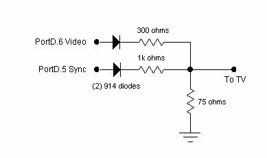
The first piece of hardware was a digital to analog converter used to create the video signal. A schematic of the simple 3-resistor, 2-bit DAC is shown below:
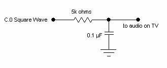
The next piece of hardware is the audio filter. At first we just tried to use a 5k resistor between output and ground because the TV is AC coupled and will slowly charge up and cut off the audio. We found that that the quality of the sound was poor, so we added a capacitor to ground to act as a low-pass filter. The schematic of this circuit is shown below:
The more complicated part of this project was figuring out how the gun works, and integrating it into our project. In order to do this, we brought an NES into the lab, and actually played the original Duck Hunt while examining all of the leads going out of the gun into the Nintendo. We did some research and found a general idea of how the gun worked, but it was important to get the specifics about the signals it output. It turns out that nothing is emitted from the gun. It consists of a photodiode which produces a high signal for a duration of 2.5ms after white light is detected on a television screen. The gun does not detect white light on anything other than the television screen, such as a computer monitor or even the 60Hz fluorescent lights. The other signal of importance was the trigger pull. Whenever the trigger is held down, the signal went low. The only other two pins we needed to use on the gun were power and ground. The pinout of the light gun is shown below:
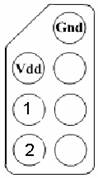
1 is the light sensor output
2 is the trigger pull output
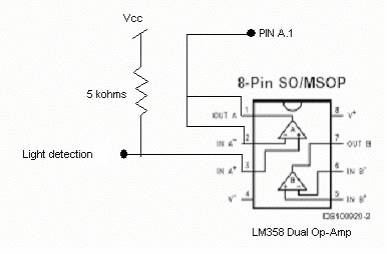
When wiring up the gun independent of the Nintendo, the
outputs did not work correctly. In order
to correct for this, we needed to add a pull-up resistor to the trigger-pull
signal. For the light detection output,
we needed to add an op-amp wired as a voltage follower along with a pull-up in
order to acquire the proper signal.
These circuits are shown below.
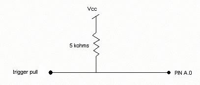
On the STK500 board, we used Port D as the output for video, Port C for audio, and Port A for the light detection and trigger pull signals.