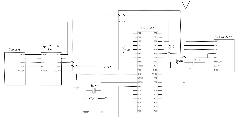
Computer Side Hardware:
The computer side hardware is shown in the figure
below. The computer connects to the
microcontroller through a 6-pin min-DIN plug and provides power to run both the
microcontroller and the receiver, thus there is no need for any batteries. The
specification for keyboards is that they should draw no more than
100mA, which is sufficient for our purposes.
The Clock line connects to pin 5 of PORTA and the Data line connects to
pin 4 of PORTA on the microcontroller.
These pins are always set to input with pull up resistors so that the
Clock line and Data line are pulled high when the lines are idle. We use a 510 Ohm resistor to connect the
Clock line to pin 7 of PORTA and another 510 Ohm resistor to connect the Data
line to pin 6 of PORTA. We use these resistors so that we can pull the Clock
and Data lines low using pins 7 and 6 respectively without shorting pins 5 and
4 to ground and burning out the port pins.
The microcontroller receives data from the wireless keyboard using the
Radiotronix receiver (RCR-433-RP). The
data output of the receiver is passed to the RXD pin of the
microcontroller. As a result, the UART
handles all the signal reception in the background for us. Like for the transmitter, we use a dipole
antenna made from a piece of wire that is about 2 feet long.