 |
Hardware Design
The hardware we use to implement Cantneroid include an STK500 board, an ATMega32 Microcontroller chip, a 5 inch portable black and white television screen, and a Sega Genesis controller pad.
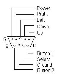
The Sega Genesis controller was not particularly difficult to implement. The pin connections are as follows:
|
Figure 1: Pin assignments for the Sega Genesis controller pad
The Select bit can help choose from multiple functions as follows:
Pin |
Function (Select = GND) |
Function (Select = 5V) |
1 |
Up |
Up |
2 |
Down |
Down |
3 |
- |
Left |
4 |
- |
Right |
5 |
+5VDC |
+5VDC |
6 |
Button A |
Button B |
7 |
Select |
Select |
8 |
Ground |
Ground |
9 |
Start |
Button C |
Table 1: Pin assigments with multiplexer input
When the Select bit is a particular value to obtain various pushes, the voltage
on the pin goes from high to low upon the button push. So, for instance,
if the Select bit is set to GND and Button A is pressed, the voltage on
PIN 6 goes from 5V to 0V upon the press. It is in this way that we are able
to develop a scheme to control the game. Cantneroid uses the following from
the controller pad: Left, Right, Start, and Button B. Left/Right move the
paddle, Start allows the user to start/restart the game after dying, and
Button B allows the user to shoot the ball after positioning the paddle.
Two bits of port D (D.5 and D.6) are used to generate three video levels: Sync level = 0 volts, black level = 0.3, and white level = 1.0. The DAC is shown in Figure 2.
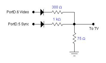 |
Figure 2: DAC circuit
Generating sound for the game was actually quite simple because
no coding was required. All of the sound generation was handled directly by
hardware.
By assigning 0x1F to the TCCR2 (Timer 2 control) register, we could toggle
the OC2 pin (output on PORTD.7) with a clear-on-match condition. Inherent in
this assignment was also a prescalar of 1024 off the full clock speed of 16
MHz. With this prescaled value, we could achieve a wide array of notes by assigning
values ranging from 10 – 100 to the OC2 pin. These values simply dictated
how often the timer would clear and toggle the pin thus creating a different
pitch for each value. To turn the sound off, we simply assigned 0x00 to TCCR2.