Software Design
In the
UBRR = ![]() =
= ![]() = 31
= 31
where the
We poll the UART once per television frame,
or 60 times per second, by calling get_the_command(
) which checks the new data received flag held by the seventh bit of the
UART Control Status Register A (UCSRA) register. If new data has been received, we obtain this
new data by reading the contents of the UART Data Register (UDR).
There are three types of bytes:
Status
Note
on: 0x9y, where y indicates midi channel
Note
Reference
Note: Middle C = 0x60
Velocity
How
fast a note is played.
Playing a note generates 6 bytes of
information:
Byte 1 Byte 2 Byte 3 Byte
4 Byte 5 Byte
6
0x90 0xYY 0xWW 0x90 0xYY 0x00
The first 3 bytes indicate that note
0xYY started playing at velocity 0xWW.
The last 3 bytes indicate that note 0xYY stopped playing. For the synthesizer we used, a NoteOff
message consisted of a NoteOn status byte followed by a velocity byte with a
value of 0. Note that some synthesizers send
the NoteOff message using a separate status byte (0x8y) with an arbitrary
velocity value.
To interpret the
To determine the note playing, we cycle
through the data received by the UART six bytes at a time and extract the
second and fourth bytes which hold the note information using the following flow
of code.
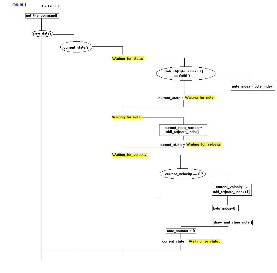
Figure 4:
In the flow diagram, current_note_number holds the note that
is currently playing. Function draw_and_store_note( ) stores the
current note and updates the screen array whose contents get painted to the
screen at a rate of 60Hz. The current_state is updated at a rate of a
little less 1/t or sixty times per second.
To keep track of the note duration we use variable note_counter which gets incremented between the time the note
starts playing and the time it stops playing in increments of 1/60 sec. Since we only care about when a note stops
playing, we only process the NoteOff velocity byte.
Once the note number and note duration
are extracted they are processed to obtain the note number and note type. To obtain the note number we can mod the note
by 12 because there are only 12 different notes. The following table shows notes with their
note numbers.
|
Note Number |
Note |
|
0 |
C |
|
1 |
C# |
|
2 |
D |
|
3 |
D# |
|
4 |
E |
|
5 |
F |
|
6 |
F# |
|
7 |
G |
|
8 |
G# |
|
9 |
A |
|
10 |
A# |
|
11 |
B |
We obtain the note type by comparing note_counter to duration bounds enumerated to correspond to the
note types. We enumerated bounds for five
types of notes: whole, half, quarter, eighths, and sixteenths. We created the bounds based on 2 beats per
second timing which corresponds to 2 quarter notes per second and a bound of
[22, 45] sixtieths of a second for the quarter note. The bounds for the remaining four notes can be
calculated from this bound to obtain the bounds seen below.
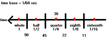
Figure 6: Note duration bounds
corresponding to the five different note types
Drawing
Routines
The TV
screen is modeled as a 100x16 byte array we called screen, which
corresponds to a y coordinate range of [0, 99] and a x coordinate range of [0,127]. We can access this array either directly or
by using functions video_pt and video_line. Function video_pt takes parameters for
the x coordinate and y coordinate and whether to draw, erase or invert the intensity
level (i.e. make the point blink).
Function video_line takes a second pair of coordinates in
addition to the parameters of video_pt.
The TV screen is drawn by sending the contents of the screen
array to the TV using assembly code for speed efficiency.
In order to draw sheet music, we must
load the screen array with the raster
array corresponding to the current sheet music.
When using video_pt or video_line we must calculate the x and
y coordinates needed. We organized the sheet music into the
following drawing sections.
Draw the staff and the G-clef
The
staff consists of 5 lines which we spaced at BTW_LINES = 5 along the y axis of
the screen array. The G-clef starts at CLEFF_X_START = 7 along
the x axis of the screen array. We
draw three staffs and a G-clef on each staff at initialization time using a
function draw_staff( ) and draw_clef( ) respectively. When auto scrolling or resetting the sheet
music we redraw the staffs and clefs by direct memory copy of
the screen values corresponding to a
staff and a clef from one part of the screen to another part of the screen.
Draw the note
We implemented
a function called draw_note( ) to
draw the notes. The function takes in
the note number, note type, and whether a note is to be drawn or erased. The note number is used to assign the correct
starting y coordinate of the note to a variable, starting_y, using a switch statement. The note type is used to determine how the
note will look. Different parts of the
note are drawn based on the note type as shown in Figure 7. We split the drawing into parts and size-inefficiently
repeated them because we don’t want to worry about the ending x and y coordinates
which would change based on the note drawn.
Thus our note drawing routine is general in that it can easily draw the
notes and update the x and y coordinates consistently as the three staffs fill
up. Also, it is more time-efficient to
have separate branches that draw all of each note’s pieces, rather than have
several if statements that must be evaluated for every note, regardless of
whether necessary.
There
are two special categories of note numbers that require special drawing
routines. The first category consists of
sharp notes which require a pound sign appended to the front of the note. The second category consists of notes C and
C sharp which require a middle C line.
To deal with these special cases we used two flags sharp and draw_c_line which
when set enable the drawing routine to add the required images.
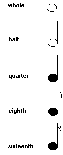
Draw stem
Draw stem; fill note in
Draw stem; fill note in; draw first flag
Draw stem; fill note in; draw first
flag; draw second flag
Figure 7: Note Drawing based on note
types
Auto scrolling
Since only three staffs, amounting to
only 18 notes, fit on the TV screen, we have implemented automatic scrolling to
allow the user to easily create nine staffs worth of music. The second staff is first copied onto the
first staff and the third staff is then copied onto the second staff by copying
from and to the proper portions of the screen
array. The third staff is then erased (or
cleared) by setting that portion of the screen
array to 0. The third staff is then
reset by copying the staff lines and G-clef from the second staff portion of
the screen array. The user can continue playing the instrument
until the ninth staff is filled at which point an “OUT OF SPACE D FOR PRInT”
message pops up. We chose to do all of
the scrolling with direct memory copies because it turned out to be a much
faster implementation than redrawing notes.
This is because function calls to draw_note()
and array accesses for stored notes can be quite expensive.
Reset
The
user may be unsatisfied with the sheet music just created and wish to delete
it. We have implemented such
functionality to satisfy this demanding user.
He or she only needs to press # on the keypad, and the sheet music will
be magically reset. Once the # key is
pressed, the UART is enabled to receive
Transmission to the TV
Transmission to the TV
is very time sensitive. That is, the screen
line lengths must be the same in order not to cause jitter. We used a line length of:
![]()
The NTSC standard uses horizontal syncs to indicate the end of a line and
vertical syncs to indicate the end of a frame, see Figure 8.
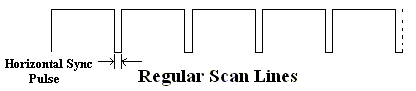
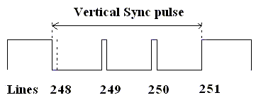
Figure 8: Horizontal and Vertical sync pulses
The horizontal sync pulse
is approximately 5.4µs. The duration of
the vertical sync pulse is three times a scan line or:
![]()
The timing is
scheduled using the timer1 compare on match Interrupt Service Routine (ISR). Every 1018 ticks, the timer1 compare match
generates an interrupt and the ISR is entered.
Here, the appropriate sync pulse is generated and a line count is maintained. The interruption rate of the ISR creates a
time base of 63.625 µs and a frame rate of approximately 60 Hz:
![]()
The actual
NTSC standards for
the horizontal and vertical syncs are 5µs and 63.55 µs respectively. The
differences between our values and the NTSC values are very small. In addition, while one must be extremely
careful in time-scheduling for television output signals, it turns out that as
long as the signal is within a certain range of the expected values, if the
signal is consistent, the output signal will function as expected. Thus, a major concern is not only that the
refresh rate used (63.625 us) falls close to the NTSC value (63.55 us), but
that the refresh rate is always
the same.
The output to the TV is generated as
follows. In the endless while loop of main( ), the index for the next line to
print is computed and then the processor sleeps while awaiting an interrupt
from timer1. Once timer1 has generated
an interrupt, the processor awakens and, if printing is between lines 31 and
230 of the frame, it outputs the contents of the screen array to the screen by first loading 8 registers and quickly
dumping them to Pin 6 of PORTD for each
of these lines. If printing has reached
the last 32 lines of the frame, the processor computes the screen array contents for the next frame.
Graphical
User Interface
We wrote the application for PC
interaction with our system using Microsoft Visual Basic. We chose this language because of the ease of
creating simple GUI forms with VB. We
used the MS Comm Control to communicate with the microprocessor. We then wrote code to access a binary file,
write bitmap header hex values, and write the screen raster sent by the mcu to
the file. Once the bitmap is created, the
application allows the user to display and print the object with VB’s Printer.paintpicture
function.